
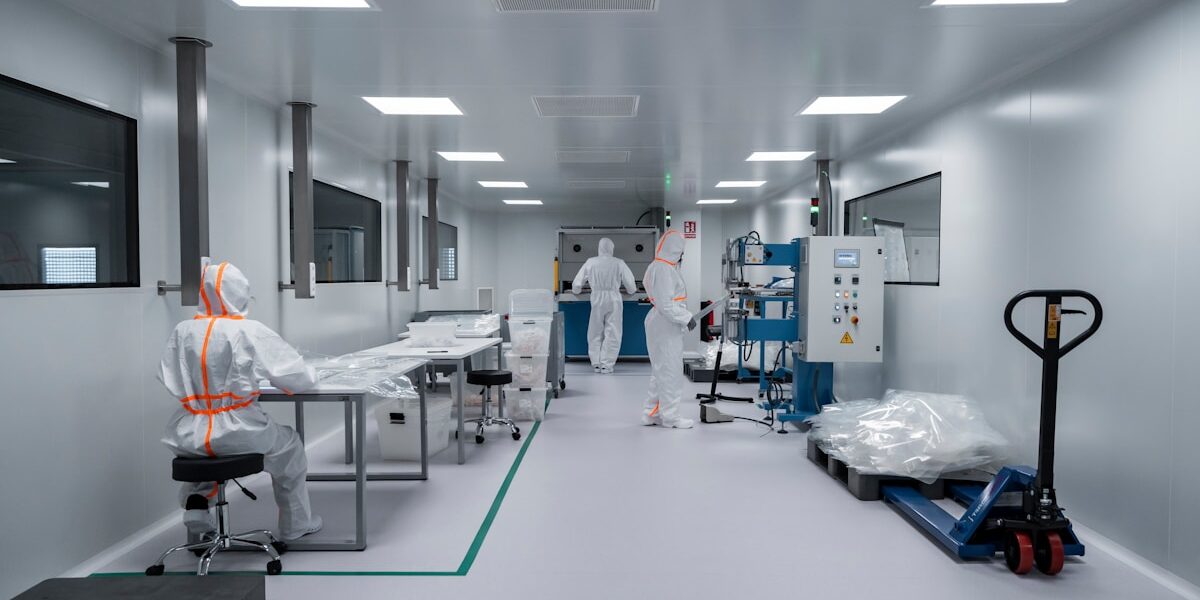
Installing a clean room sliding door is a high-stakes balance between speed and sterility. You need the unit operational to meet construction schedules, but a single misalignment in the header track can compromise your pressure cascade for years. This quick-start guide cuts through the noise to focus strictly on the execution steps that prevent costly rework and ensure you meet your deadline.
For a standard manual installation, your wall cut-out must provide at least 81 inches of height and 36 inches of width to accommodate the frame and track assembly without forced modification. We cover how to verify this structural integrity, along with the correct tools for aligning the overhead track and the specific techniques for sealing elastomeric gaskets to maintain airtightness. Get this right, and you avoid the most common pitfall: post-installation air leaks that fail smoke tests.

Check Site Readiness Before Delivery
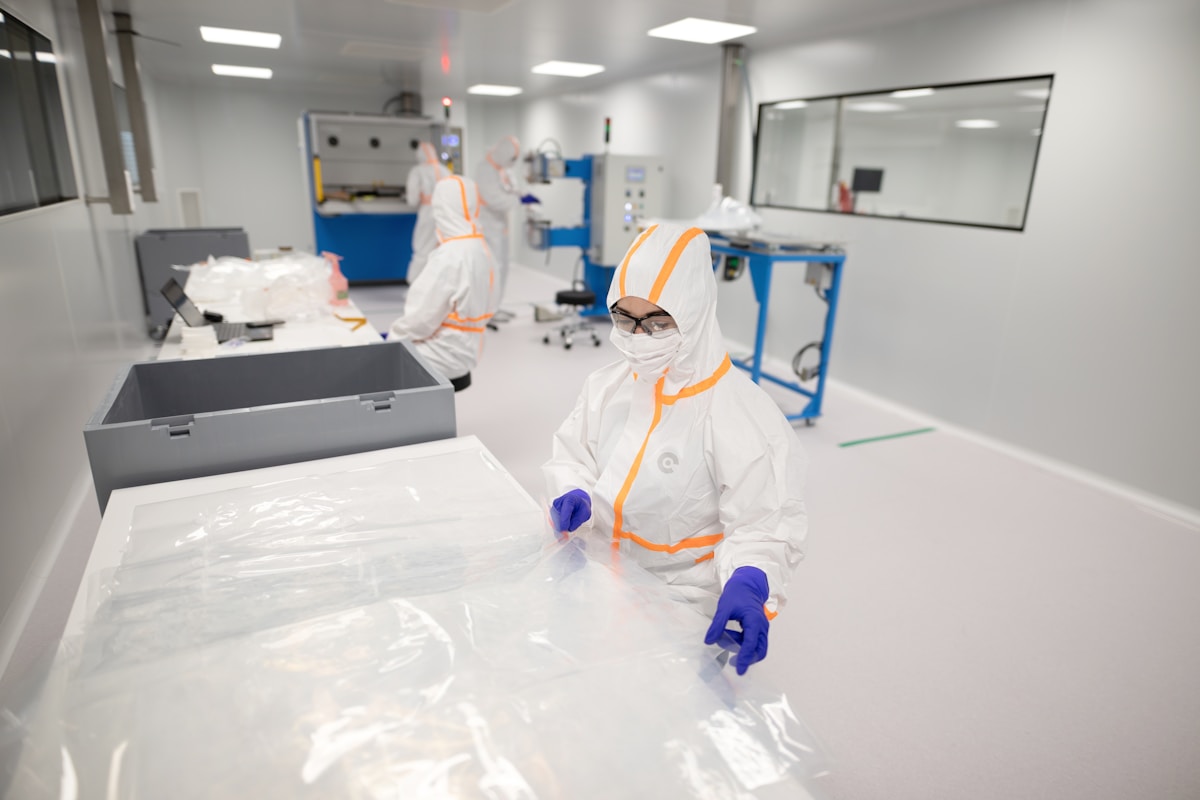
Before delivering a clean room sliding door, validate the building envelope for structural capacity, dimensional accuracy, and mounting integrity. Site mismatches are the primary cause of track misalignment, seal failure, and ISO audit non-compliance during commissioning.
Verify Wall Thickness and Load-Bearing Capacity
Sliding door systems transfer dynamic operational loads directly into the surrounding wall structure. Metal sandwich panel partitions, which are standard in pharmaceutical and cold storage facilities, frequently lack the inherent rigidity to anchor sliding hardware without additional reinforcement. If the wall cavity cannot support the combined mass of the door leaf and track forces, the panel will deform over time, breaking the hermetic seal and allowing unfiltered air infiltration.
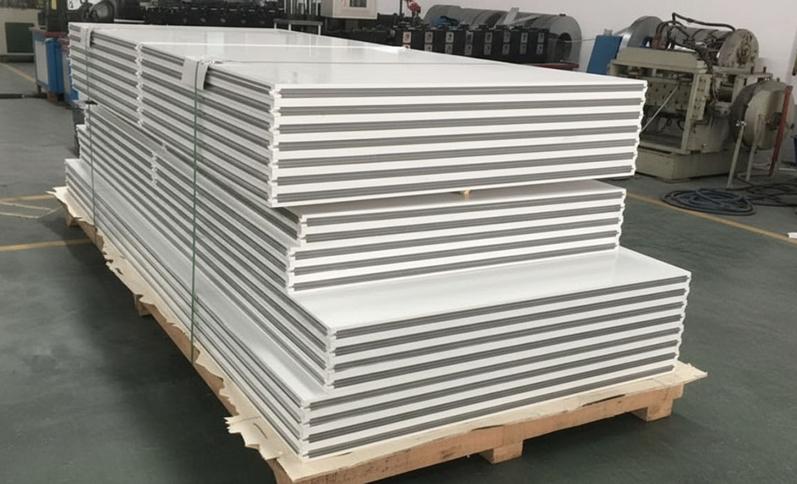
We specify lightweight structural rigidity for clean room applications because reduced leaf mass eases track installation and minimizes long-term wear while delivering the flat, durable surface required for hermetic sealing. Composite sandwich panels from manufacturers like Rax Panel provide the necessary stiffness-to-weight ratio, keeping the sliding assembly stable without overloading the partition. Our engineering team calculates the door leaf weight against the wall’s structural rating and adds secondary framing where metal sandwich panels require supplemental support.
Skipping this validation pushes the risk of fastener pull-out and subsequent seal degradation directly onto the facility operator. When the substrate cannot absorb the dynamic load, compression seals lose uniform contact across the frame perimeter, which fails GMP airtightness checks during initial commissioning.
Measure Rough Opening Dimensions and Squareness
The rough opening must accommodate the door frame, compression seals, and thermal break layers without forcing installers to shim or cut around irregular geometries. Deviations in squareness generate point loads along the overhead track, which eventually cause the door leaf to bind, drift off-center, or wear prematurely. Proper dimensional tolerance allows the frame to sit plumb and level, ensuring consistent compression across the entire seal perimeter under repeated cycling.
Even minor dimensional variances in existing openings can compromise airtightness ratings and whole-wall thermal performance, especially in temperature-controlled clean rooms. Our procurement guidelines prioritize precise custom cuts and engineering-grade tolerances when specifying composite panel materials, guaranteeing that the door assembly integrates smoothly with the wall plane. Installers should measure diagonal offsets and verify that all corners fall within acceptable squareness thresholds before proceeding with frame anchoring.
When rough openings are out of tolerance, the frame must be forced into position, which distorts the gasket compression and creates micro-gaps invisible to the naked eye. These gaps become the exact pathways that allow non-classified air to migrate between adjacent ISO zones during production runs.
Confirm Ceiling Track Mounting Surface Integrity
The overhead track carries the full dynamic weight of the sliding leaf during operation, making the mounting substrate non-negotiable. Suspended ceilings, thin metal decking, or unverified structural members cannot reliably anchor sliding door hardware; the track must be secured directly to a reinforced load-bearing element. If the mounting surface lacks adequate capacity, vibration and friction from repeated cycles will loosen fasteners, leading to track sag and operational failure mid-shift.
Our team evaluates the header area for both static and dynamic load resistance prior to equipment delivery. Reinforcing the mounting plane with steel channels or approved structural backers ensures long-term alignment and reduces maintenance intervals in high-throughput pharmaceutical clean rooms. Lightweight composite door leaves ease this requirement significantly, but the track still demands a rigid anchor point that can absorb constant lateral forces without deflection.
Failure to verify the mounting surface shifts the entire burden of structural support onto the ceiling grid, which was never engineered for sliding hardware loads. Once the track begins to flex, the door leaf loses vertical stability, causing seal compression to vary cycle-by-cycle until the assembly fails cleanroom classification standards.
Check Floor Levelness for Bottom Guide Rails
Bottom guides stabilize the door leaf and prevent swinging or lateral drift, requiring a perfectly leveled substrate to function correctly. Uneven floors force the guide rail into inconsistent contact with the door edge, increasing friction and accelerating wear on both the hardware and the panel finish. In washdown environments, poor leveling can also trap contaminants beneath the rail, creating hygiene violations under ISO cleanliness standards.
Clean room sliding door installation specifications demand that floor surfaces be verified for levelness before the bottom guide is anchored. Any deviations should be corrected with leveling compounds or shims that remain chemically compatible with the facility’s daily sanitation protocols. Ensuring a flat, debris-free substrate supports smooth operation and maintains the hygienic, washable surface required for sterile processing areas.
When the bottom guide sits on an uneven plane, the door edge experiences cyclic impact loading every time the leaf passes through the threshold. This micro-shock transfers directly to the panel skin, which can eventually crack the gelcoat or warp the composite facing, exposing the core to moisture and degrading the door’s thermal insulation value.
| Readiness Check | Technical Requirement | System Impact | Verification Action |
|---|---|---|---|
| Rough Opening Tolerances | Frame width + 1.75″ clearance; height + 3.5″ clearance | Ensures compression seal engagement and maintains <0.5 ACH at 75 Pa airtightness | Laser measure rough opening; confirm plumb within ±2mm/m prior to installation |
| Substrate Load Capacity | Reinforced wall/ceiling rated for composite panel leaf mass plus track dynamic load | Prevents track misalignment, reduces sliding wear, and supports lightweight high-rigidity door leaves | Calculate door leaf weight against structural ratings; specify secondary framing for metal sandwich walls |
| Surface Flatness & Hygiene | Ra ≤ 0.8μm finish; completely debris-, dust-, and moisture-free substrate | Enables hermetic sealing, supports washable cleanroom surfaces, and meets ISO 14644-1 classification | Use surface profilometer; perform white-glove inspection for contaminants prior to installation |
| Ambient Installation Conditions | Temperature 10–35°C; relative humidity <70% during sealant and adhesive cure | Prevents moisture absorption in foam cores and mitigates condensation or delamination risks during cure | Record daily site environmental logs; suspend sealant application if thresholds exceed cure specifications |
| HVAC & Pressure Differential | Stable differential ≥10 Pa per EU GMP Annex 1; complete smoke test before final seal | Validates pharmaceutical airtightness and confirms cleanroom pressurization strategy | Run blower door and smoke tests; verify differential pressure monitors are calibrated and active |
| Thermal Bridge Continuity | Uninterrupted insulation path at frame-to-wall junction matching core R-value target | Maintains cold storage thermal performance and eliminates condensation points at door frames | Cross-check framing thermal breaks against selected core specification (PU, XPS, PET, or PVC foam) |

Gather Essential Tools for the Job
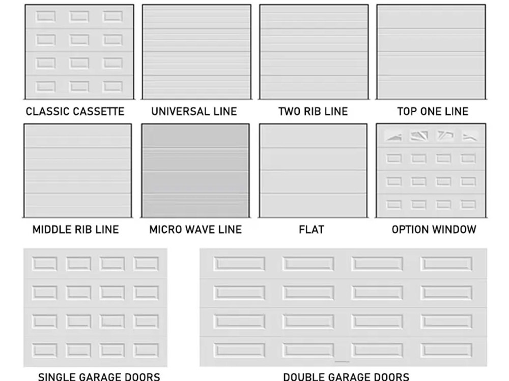
Precision tooling prevents composite panel damage and ensures cleanroom sliding door tracks align within millimeter tolerances.
Installing a cleanroom sliding door assembly requires precision tooling that prevents damage to lightweight composite panels while maintaining strict dimensional tolerances. The essential toolkit includes cordless drills with adjustable torque, laser levels, sealant guns, and vacuum lifters. Each tool addresses a specific risk: over-torquing fasteners, misaligned tracks, sealant contamination, or panel fracture during handling. Selecting equipment rated for composite materials ensures the installation meets ISO cleanliness and structural integrity standards.
Cordless Drills with Adjustable Torque Settings
Composite panels and aluminum frames react differently to mechanical fastening. Applying excessive torque cracks the outer skin or strips screw holes in softer core materials. A cordless drill with adjustable torque eliminates guesswork by disengaging the driving mechanism once a preset resistance is reached.
Think of torque adjustment like tightening a bolt on a fragile glass table—it applies just enough force to hold securely without snapping the surface. This feature protects both the panel facings and the underlying core structure, whether the panel uses fiberglass reinforced thermoplastic (CFRT), glass fiber reinforced polymer (GRP), or foam cores.
- Torque range: Select a model offering at least 15–20 Nm of adjustable torque for standard cleanroom fasteners.
- Clutch mechanism: Use a multi-position clutch to prevent overtightening on brittle materials like carbon fiber reinforced polymer (CFRP) or thin GRP skins.
- Bit retention: Magnetic bit holders reduce slippage, preventing scratches on washable panel surfaces.
Laser Levels for Track Alignment Verification
Overhead track alignment determines whether the sliding door operates smoothly or binds against guide rails. Even a minor deviation of a few millimeters causes uneven wear and compromises seal integrity. A laser level provides a continuous reference line across the mounting surface, allowing installers to verify horizontal and vertical planes before drilling.
A laser level acts like a perfectly straight string line, but visible from any angle in a crowded workspace. This reference ensures the track remains parallel to the floor opening, which is critical for maintaining pressure differentials in ISO-classified rooms.
- Line projection: Choose a self-leveling laser that projects both horizontal and cross-line references for rapid track positioning.
- Range accuracy: Verify laser accuracy specifications over the intended mounting span, typically within ±1.5 mm at 5 meters.
- Mounting compatibility: Ensure the laser has a threaded mount for standard tripod attachment in confined cleanroom spaces.
Sealant Guns Loaded with Cleanroom Silicone
Sealant application seals gaps around door frames, preventing particle migration and maintaining pressure differentials. Standard sealants may outgas volatile organic compounds that contaminate controlled environments. Cleanroom-rated silicone cures without releasing contaminants and maintains flexibility under repeated washdown cycles. This material behaves like a flexible gasket rather than a rigid glue, accommodating structural movement without leaking particles. A quality sealant gun delivers consistent bead width and pressure control, which is essential for creating continuous, washable joints around sliding door frames.
- Cartridge type: Use 300 ml or 600 ml cartridges compatible with standard manual or pneumatic guns.
- Cure profile: Select neutral-cure silicone to avoid corrosion on metal frames and adhesion failure on composite substrates.
- Bead consistency: A smooth-feed gun prevents air pockets in the sealant, ensuring uninterrupted joints.
Vacuum Lifters Rated for Composite Panels
Composite panels are large, lightweight, and susceptible to bending or edge damage when carried manually. Vacuum lifters distribute holding force evenly across the panel surface, allowing safe positioning against overhead tracks and wall openings. Properly rated equipment prevents drop incidents and reduces installer fatigue during repeated lifts.
A vacuum lifter works like a large suction cup, spreading the grip across the entire sheet so thin panels do not flex or crack under their own weight. This method is especially important for heavy sandwich panels with honeycomb or dense foam cores.
- Load capacity: Match the lifter rating to the heaviest panel variant, including frames and hardware assemblies.
- Pad material: Use soft-touch rubber pads to grip smooth gelcoat or painted surfaces without marking.
- Release mechanism: Electro-pump systems with fail-safe batteries ensure the panel remains secured if power is interrupted.

Follow Safety and Cleanliness Standards
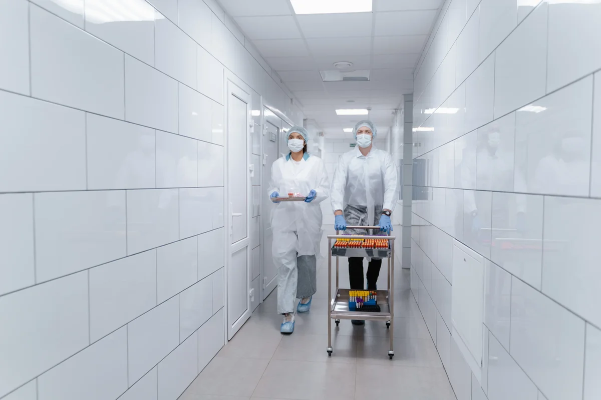
Safety and cleanliness protocols are non-negotiable in cleanroom installations. Proper PPE, dust management, surface decontamination, and access control prevent personnel injury and protect ISO-classified environments from cross-contamination.
Wear Appropriate Personal Protective Equipment
Composite sandwich panels, fiberglass-reinforced sheets, and aluminum honeycomb cores present distinct physical hazards during handling and fabrication. Sharp panel edges, loose fiberglass filaments, and rigid thermoplastic dust require standardized personal protective equipment (PPE) before any contact occurs.
Installers must wear cut-resistant gloves rated for sheet metal and composite handling, safety goggles with side shields to block airborne micro-particles, and fitted N95 or P100 respirators when cutting or drilling. Steel-toed footwear remains mandatory because large-format panels can shift unexpectedly during manual positioning.
- Gloves: Kevlar-lined cut-resistant gloves prevent lacerations from raw composite edges and fiberglass roll borders.
- Eye Protection: Polycarbonate safety glasses with tight seals stop fine resin dust and fiberglass strands from entering the tear ducts.
- Respiratory Gear: A sealed N95 mask filters airborne particulates generated when drilling through foam cores like XPS, PET, or PVC.
- Coveralls: Disposable lint-free smocks prevent skin shedding and external contaminants from transferring into the sterile zone.
Implement Dust Control Procedures During Drilling
Drilling into composite sandwich panels releases fine particulate matter that behaves like invisible smoke inside a sealed room. Unlike standard wood or drywall, layered cores such as PMI foam, aramid honeycomb, or closed-cell polyurethane trap fibers deep inside the panel matrix.
Once released, these particles settle onto HVAC filters, cleanroom ceilings, and door seal interfaces, forcing costly decontamination cycles. Drilling without containment is like sawing plywood indoors without a tarp—the microscopic dust floats everywhere and lands in places a regular broom cannot reach.
All drilling operations must connect directly to a HEPA-filtered industrial vacuum positioned within twelve inches of the drill bit. Wet-cutting methods are preferred whenever material compatibility allows, as moisture binds heavy particles before they become airborne. If dry drilling is unavoidable, work zones must be isolated with polyethylene sheeting and negative-air pressure generators.
- Tool Setup: Attach a vacuum shroud to every cordless drill and verify suction pressure before piercing the panel skin.
- HVAC Isolation: Shut down or seal nearby supply and return air diffusers to stop dust migration through pressurized airflow.
- Post-Cut Cleaning: Wipe drilled holes with isopropanol-dampened lint-free wipes to remove residual resin dust from the core exposure.
Sanitize Composite Panel Surfaces Before Cleanroom Entry
Cleanroom sliding doors rely on continuous, smooth surfaces to maintain bio-decontamination effectiveness. Many pharmaceutical-grade panels feature molded gelcoat finishes or flush fiberglass faces designed to reach a surface roughness average (Ra) of ≤0.8 micrometers. In plain terms, Ra measures how many tiny peaks and valleys exist on the surface under magnification. A lower number means a smoother finish, which allows hydrogen peroxide vapor (HPV) sterilization cycles to penetrate every microscopic crevice without leaving viable microbial colonies behind.
Before any panel crosses the cleanroom threshold, installers must wipe the entire exposed face with a compatible cleanroom disinfectant. Abrasive scouring pads, wire brushes, or solvent-heavy chemicals must be avoided because they scratch the protective topcoat. Even a hairline scratch increases surface area for bacterial adhesion and breaks the smooth-wipe requirement mandated by ISO 14644 cleaning validation protocols.
- Pre-Entry Wipe: Use single-use polyester lint-free cloths saturated with 70% isopropanol or quaternary ammonium solution.
- Edge Sealing: Inspect cut edges for exposed core material and apply cleanroom-rated epoxy or silicone sealant to prevent fiber shedding.
- Surface Inspection: Run a white glove test over high-traffic zones like door leaf faces, track mounting brackets, and threshold guides to confirm zero visible residue.
Maintain Controlled Access Zones During Installation
A cleanroom is not a standard construction site, and treating it as one guarantees contamination failure. The moment a sliding door assembly enters an ISO-certified space, the surrounding corridor, header track cavity, and bottom guide rail area become temporary quarantine buffers.
Uncontrolled foot traffic, unprotected wall penetrations, and open ceiling plenums act as direct highways for outdoor air contaminants. Think of the cleanroom buffer zone like an airport security checkpoint; mixing dirty construction traffic with sanitized sterile traffic guarantees a breach.
Installation teams must establish marked exclusion zones using low-profile barricade tape or rigid polyethylene partitions. Only personnel with active site badges and signed contamination control log entries may pass through. One-way traffic flow should be enforced so dirty boots never cross over already-sanitized floor tracks or header channels. Open wall cavities and unsealed ceiling access panels require temporary gasketed covers until the full door frame and non-shedding weather stripping are installed.
- Zone Marking: Paint or tape a two-meter boundary around every active drilling, lifting, and sealing operation.
- PPE Gowning: Require full cleanroom suit progression, including booties, hair covers, and face masks, before crossing the buffer line.
- Tool Accountability: Log every power tool, fastener box, and sealant cartridge entering the zone to prevent foreign object debris (FOD) retention.
- Temporary Covers: Apply anti-static polyethylene film over open wall frames and ceiling voids to block dust fallout onto freshly installed tracks.

Mount the Header Track and Frame
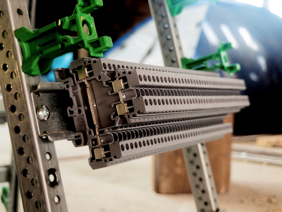
A cleanroom header track must be leveled within ±1 mm across its full span and anchored directly into the building’s primary structural frame. Even minor deviations compound under repeated cycling, causing panel binding, seal degradation, and premature roller failure.
Why Track Levelness Dictates Long-Term Door Performance
In a cleanroom environment, the overhead track carries both the static weight of the sliding panel and the dynamic forces generated during every open-and-close event. When the rail is not perfectly horizontal, gravity continuously pulls the door toward the low point. Think of it like a book sliding across a slightly tilted table: even a tiny angle creates steady resistance. Over time, that resistance accelerates roller wear, stresses the bottom guide rail, and compromises the perimeter gasket seal.
Industry practice requires a digital laser level to verify the mounting surface before any fasteners are driven. The acceptable tolerance is typically within ±1 millimeter across the entire track length. For a standard cleanroom corridor spanning several meters, this means the high and low points must differ by no more than 1 mm from one end to the other. If the substrate is uneven, precision shims or a leveled mounting plate are used to correct the plane before final anchoring.
Anchoring Strategy for High-Cycle Operation
A cleanroom sliding door assembly is engineered to withstand 50,000 open-close cycles without mechanical failure. That durability is only possible if the header track transfers its load into a structurally sound surface, not into hollow cladding, insulation boards, or non-load-bearing partitions. The fasteners must engage the primary ceiling structure, such as reinforced concrete, steel decking, or a dedicated transfer frame designed for heavy sliding assemblies.
Anchor spacing follows the track manufacturer’s engineering specification, but common practice places fasteners at each structural joist intersection and at intermediate points no more than 600 mm apart. Chemical anchors or heavy-duty wedge anchors are selected based on the substrate. In pharmaceutical and biological safety cleanrooms, the chosen anchor must also prevent air leakage paths around the penetration, which means sealant compatibility with the facility’s washdown chemicals is verified before installation begins.
- Track flatness check: Verify with a digital laser level before drilling. Any dip or rise beyond ±1 mm requires correction through shims or a leveled mounting plate.
- Structural engagement: Fasteners must bite into load-bearing concrete, steel, or a certified support channel. Gypsum board, metal stud cavities, or foam core panels alone cannot safely hold a sliding door assembly.
- Thermal bridge prevention: In temperature-controlled cleanrooms, metal-to-concrete contact points should be isolated with closed-cell neoprene or polymer spacers to stop cold spots that could cause condensation.
- Fastener torque verification: Over-tightening can warp a lightweight aluminum track, while under-tightening allows micro-movement. Follow the specified torque range and re-check after the first 24 hours of service.
Do not assume the ceiling grid or suspended acoustic tile framework can support the overhead rail. These systems are rated for their own dead load, not for the lateral and vertical forces of a repeatedly moving cleanroom door. Mounting into an unsupported grid guarantees track sag, panel binding, and rapid hardware replacement.
Final Alignment Verification Before Hanging the Door
Once the track is bolted in place, run a straight-edge along the top bearing surface and roll a small steel bearing ball across the rail. If the object stops or changes speed noticeably, the track plane is not uniform enough for smooth operation.
The roller trolley must travel the full length without manual assistance beyond the initial push. At this stage, confirm that the track centerline matches the rough opening width so the door leaf will sit flush against the perimeter gaskets when fully closed.
A properly leveled and anchored header track removes guesswork from the next installation steps. When the panel is hung, adjustment becomes a matter of fine-tuning the roller height and bottom guide clearance rather than fighting an improperly installed support system.
Hang and Align the Sliding Door
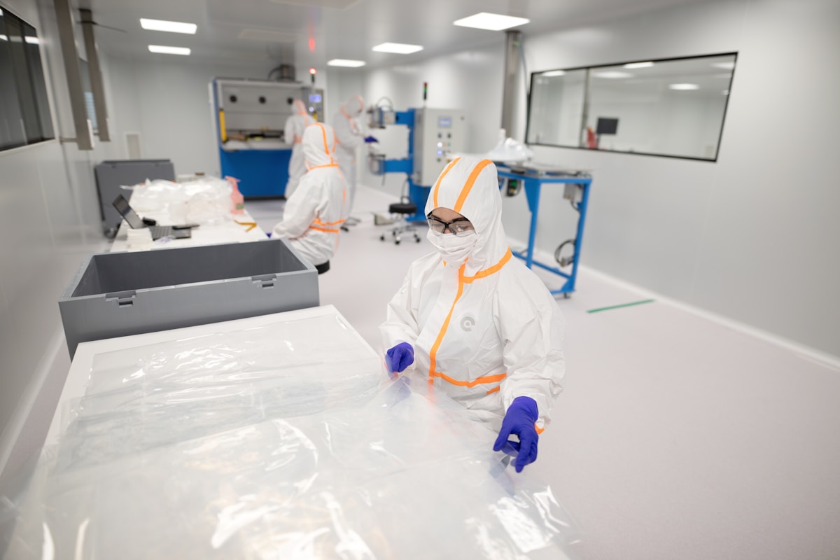
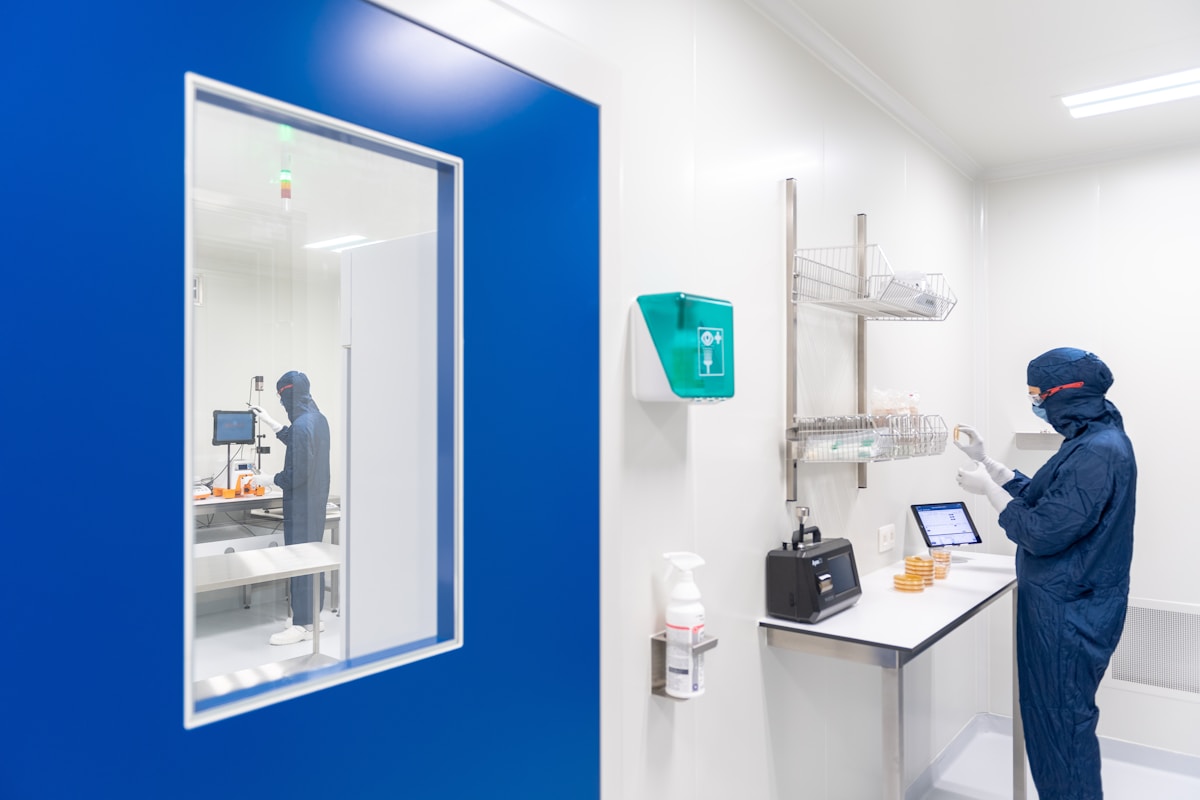
Proper suspension is the single most critical factor in preventing mechanical binding. A plumb and level alignment ensures the door leaf glides effortlessly, meeting the required 50,000 open-close cycles without premature wear on the rollers or track system.
Once the header track is securely mounted, the focus shifts to the suspension of the door leaf. For cleanroom applications using composite sandwich panels—such as those with a polypropylene honeycomb core or GRP facings—the reduced weight compared to traditional steel simplifies handling.
However, the rigidity of these panels means that alignment tolerances are tighter. If the door is not hung perfectly square, the lightweight nature of the material will not correct the error; instead, the panel will bind against the frame, damaging the seals and the track surface.
Attaching Suspension Brackets
Begin by attaching the suspension hanger brackets to the top of the door leaf. For composite panels, typically 1 ¾-inch (44mm) thick, ensure the brackets are centered precisely along the top edge to distribute the load evenly. Use the manufacturer’s specified fasteners, ensuring they penetrate the reinforcing sheet or internal sub-frame without causing delamination to the surface laminate.
- Check Fastener Grip: Tighten screws to a uniform torque specification. Over-tightening can crush the foam or honeycomb core, compromising the panel’s structural integrity and flatness.
- Verify Roller Orientation: Ensure the wheels on the suspension brackets are aligned parallel to the length of the track. Misaligned rollers will create “crabbing” motion, leading to uneven wear.
Engaging the Overhead Track
With assistance or a vacuum lifter, raise the door leaf until the suspension rollers are level with the track opening. Tilt the bottom of the door slightly towards you to hook the rear rollers into the track, then pivot the door upward to seat the front rollers.
This technique prevents the rollers from jumping out of the track during installation. Ensure that any safety locks or anti-jump clips on the hangers are engaged immediately to prevent the door from dislodging during vibration or accidental impact.
Adjusting Rollers for Perfect Travel
Achieving a “plumb” (perfectly vertical) orientation is essential for airtight sealing and smooth operation. Most industrial sliding door hangers feature an adjustment nut or screw on the vertical shaft of the hanger.
📋 Actionable Steps for Vertical Adjustment
- Step 1: Initial Positioning – Close the door so it is flush against the frame jamb. Use a spirit level against the vertical edge of the door to check for plumb.
- Step 2: Fine-Tuning – Rotate the adjustment nut on the high side of the door clockwise to lower that corner, or counter-clockwise to raise it. Make adjustments in small increments (e.g., 1/16th of an inch).
- Step 3: The Roll Test – Slide the door fully open and closed several times. Observe if the leading edge “toes in” or “toes out” as it travels. The door should maintain a consistent gap relative to the floor throughout the entire travel path.
- Step 4: Locking Down – Once plumb is achieved, tighten the locking jam nut against the adjustment nut to prevent vibration from altering the alignment over time.
Verifying Gap Consistency
The final check involves the clearance between the door panel and the finished floor. For cleanroom sliding doors, this gap is typically minimal to maintain air pressure differentials. Measure the gap at three points: the hinge side, the latch side, and the center while the door is closed.
Do not rely solely on the floor for alignment. If the floor substrate is uneven, aligning the door to the floor will result in a vertical misalignment that causes the door to bind in the header track. Always prioritize the vertical plumb of the door leaf relative to gravity and the header track, then adjust the bottom guide or threshold strips to match the door’s path.
Proper alignment ensures that the load is carried entirely by the overhead track system, with the bottom guide merely providing lateral stability. This minimizes friction, reduces the noise level during operation, and guarantees that the door mechanism will withstand the rigors of high-frequency traffic in sensitive environments like pharmaceutical or biotech manufacturing facilities.
<!– wp:html –>
<!– /wp:html –>
Install Seals, Gaskets, and Thresholds
Compression gaskets and interlocking thresholds convert a sliding composite door leaf into an airtight cleanroom envelope. Without them, pressure differentials collapse during validation.
In a cleanroom sliding door assembly, the panel itself does not create the air seal. The gasket system does. When the door closes, perimeter compression gaskets must deform uniformly against the frame to block unfiltered bypass air.
For ISO 7 and ISO 8 facilities, acceptable leakage typically sits around 0.5 m³/h at 50 Pa, while ISO 5 or sterile pharmaceutical zones often demand rates closer to 0.1 m³/h at the same reference pressure. Missing these targets during blower door or water-fog testing is the fastest route to a failed Commissioning, Operational, and Performance Review (COPR) cycle.
How to Choose Compression Gasket Profiles and Materials
Ethylene propylene diene monomer (EPDM) is the standard baseline for cleanroom door sealing. It maintains compression recovery after thousands of cycles and tolerates routine wipe-down disinfectants, including quaternary ammonium compounds and diluted hydrogen peroxide. If the environment requires frequent exposure to aggressive solvents, dry heat sterilization, or wet steam, silicone or fluoroelastomer alternatives may be necessary, though the cost premium is substantial.
The cross-sectional geometry matters as much as the compound. A D-shape or mushroom-head profile creates a self-sealing reaction: as room pressure increases, the gasket presses harder against the frame rather than leaking outward. Rectangular pads flatten completely and are far more likely to develop micro-gaps over time.
- Perimeter Gaskets: Run continuously around the frame stop, compressed by the closed door leaf. Splices must be cut at 45 degrees and bonded with compatible contact adhesive.
- Door Edge Seals: Cover the exposed vertical edges of the sliding leaf to prevent airborne particles from tracking through the panel perimeter.
- Cleaning Compatibility: Verify that the gasket material does not degrade when exposed to the facility’s validated sterilization protocol.
Installing Interlocking Bottom Thresholds
The bottom interface is the highest-risk leak path on any sliding door. Hinged doors rely on gravity to press a sweep gasket downward, but sliding leaves cannot depend on weight. They require an interlocking threshold or a bottom drag-seal rail that the moving leaf locks into.
This component must serve two functions at once: guide the door smoothly and compress against a fixed floor track to block airflow. Because sliding tracks naturally attract particulate matter, the threshold channel should feature smooth, coved interiors that can be wiped without catching debris.
A frequent installation error is applying liquid sealant directly inside the sliding track to stop drafts. This creates mechanical drag, accelerates gasket wear, and eventually compromises the operator motor. Instead, install a continuous EPDM wiper strip along the non-contact side of the track to block airborne debris while leaving the sliding plane clean.
The threshold compression face should remain free of cured adhesive or factory dust before the first cycle test. Any contamination trapped between the moving seal and the fixed rail will create a permanent leak path that no amount of adjustment can fix.
Verifying Airtightness Before Room Commissioning
Visual inspection is never sufficient for cleanroom door sealing. A gasket can appear fully seated while still allowing measurable airflow under pressure. After the sliding door is fully mounted, aligned, and connected to the operator, ramp the room to its design pressure differential, typically +10 to +15 Pa relative to the corridor. Then measure infiltration specifically at the door interface using a calibrated flow hood or smoke observation under controlled pressure.

Connect Operators and Adjust Settings
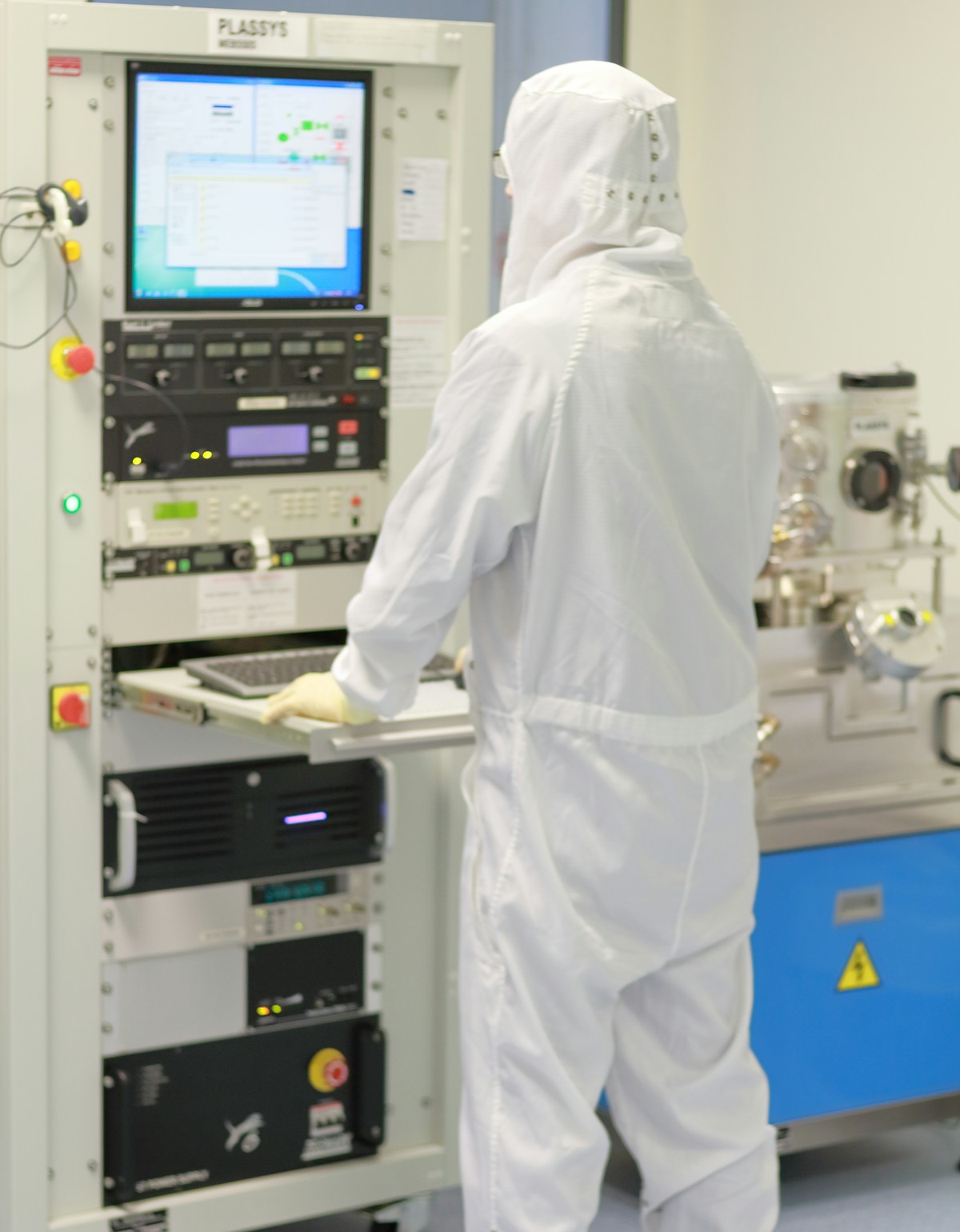
A properly wired cleanroom sliding door operator must deliver silent, consistent cycles while maintaining hermetic seals to preserve ISO room classification.
The biggest headache during cleanroom sliding door installation is not mounting the track—it is getting the operator electronics right. A single wiring mistake or misconfigured sensor can cause the door to stall, slam, or fail to seal against the frame. In pharmaceutical and biomedical facilities, these failures do not just disrupt workflow; they breach contamination controls and trigger audit flags. The solution lies in precise power routing, accurate encoder calibration, and disciplined sensor tuning.
Power Supply and Motor Wiring
Most modern cleanroom operators use a 24 V DC brushless motor. “DC” stands for direct current, which means electricity flows in one steady direction. Choosing a low-voltage DC system is standard practice in washable environments because it cuts the risk of electrical shock and reduces electromagnetic interference with nearby lab instruments. “Brushless” means the motor lacks traditional carbon brushes that wear down over time, so the unit requires less maintenance and runs much quieter than older mechanical designs.
When routing the power cables, treat the wiring like a cleanroom protocol. Exposed conductors must be tucked into sealed conduits or clipped flush against the operator housing. Dangling wires collect dust, shed particles, and create failure points that are impossible to sanitize. Connect the motor leads to the main control board using the manufacturer’s labeled terminals, and verify that the polarity matches before applying power.
- Supply Voltage: Confirm the incoming power matches the operator’s rated 24 V DC input. Mismatched voltage instantly damages the control board.
- Cable Sealing: All wire entry points must use sealed gland fittings or cleanroom-rated cable ties to prevent particle ingress.
- Encoder Feedback: An encoder works like a digital ruler inside the motor, reporting the exact door position to the controller so it knows precisely when to stop. Verify the encoder cable is seated tightly, as loose connections cause the door to stop short or overshoot its travel path.
Sensor Placement and Speed Calibration
Sensors tell the operator when to open, close, and stop. In a cleanroom corridor, two types usually work together: a motion detector for hands-free activation and a safety beam that reverses the door if anything blocks the path. Think of the safety beam like a tripwire that tells the motor to reverse before the door ever touches a person or cart.
Place the motion detector at a height that avoids false triggers from passing HVAC airflow or swinging equipment. The safety beam must span the full door width near the floor, typically below knee level, so obstacles cannot slip under it unnoticed.
Opening and closing speed requires careful adjustment. Fast cycles improve logistics throughput, but excessive speed creates pressure spikes that warp seals and compromise the room’s positive pressure balance. Start with a moderate cycle time, then fine-tune the deceleration zone so the door reaches the frame gently.
The final seal contact should be firm enough to compress the gasket uniformly, but never hard enough to bounce the leaf back open. Because cleanroom surfaces are routinely washed with aggressive chemical cleaners, all operator housings and sensor lenses must sit above splash zones and remain compatible with wipe-down sanitation routines.
- Motion Detector Range: Set to cover the approach zone without scanning adjacent rooms or intersecting hallways.
- Safety Beam Height: Position at or below 300 mm from the finished floor to catch carts, stools, and personnel.
- Deceleration Zone: Program the final 15 percent of the travel path to slow gradually, protecting both the panel edge and the seal.
Cycle Verification Before Handover
Before declaring the installation complete, run repeated open-close cycles without a person in the doorway. Listen for irregular motor noise, watch for uneven travel, and confirm the door returns to the exact same sealed position every time. Then, interrupt the safety beam with a non-destructive test object to verify immediate reversal. Finally, check the frame-to-panel gap under illumination. Any visible light leak indicates a misaligned sensor stop or a worn gasket that needs replacement.
Always document your final speed, delay, and sensitivity settings on a laminated label mounted inside the service access panel. Cleanroom operators change hands frequently, and undocumented settings lead to repeated recalibration errors.
Getting the electronics right transforms a heavy composite panel into a predictable, hygienic access point. The goal is invisible operation: silent movement, flawless sealing, and zero maintenance surprises during routine facility audits.

Fix Common Installation Mistakes
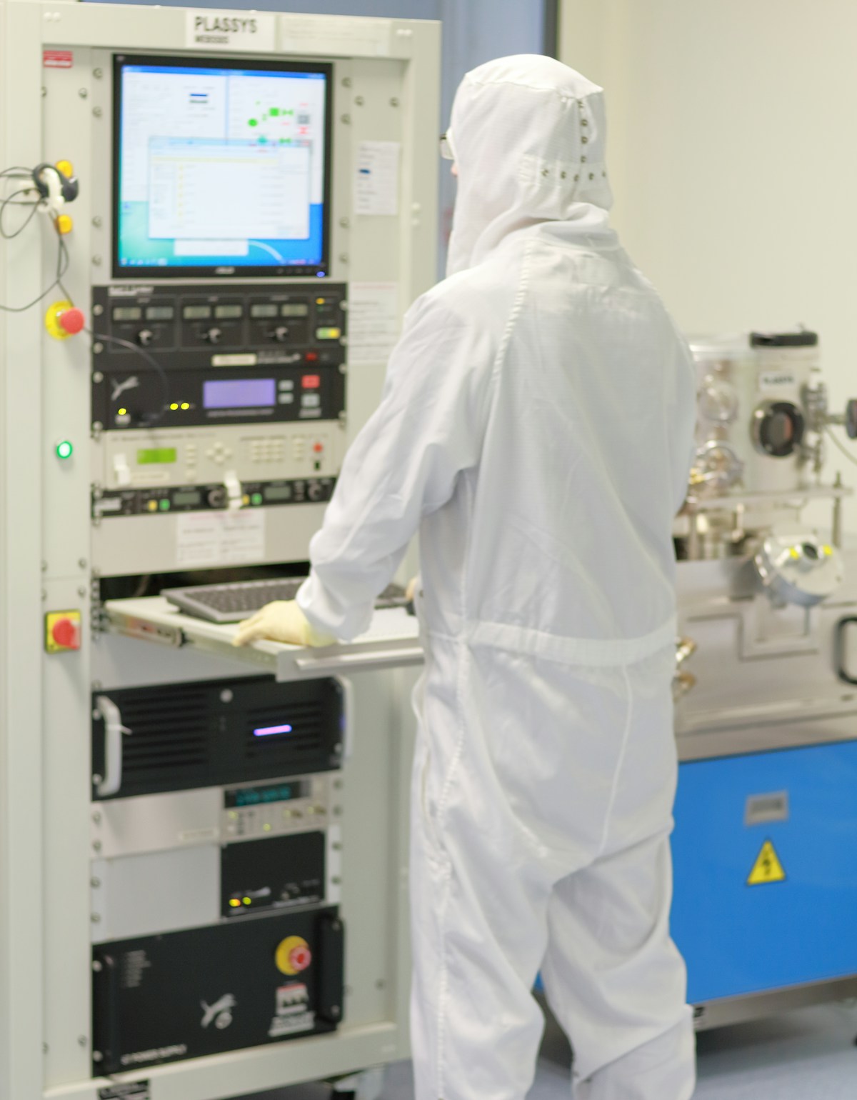
Cleanroom sliding doors frequently fail validation audits due to simple installation errors rather than component defects. Fixing track alignment, sealant integrity, guide rail clearance, and panel edge damage restores ISO compliance and extends hardware lifespan.
When a cleanroom sliding door is misbehaving, the issue usually sits at the installation interface, not inside the hardware. Minor deviations in track positioning, seal continuity, or panel edges compound rapidly under repeated cycling, leading to binding, air leakage, or contamination harborage. Addressing these faults immediately prevents costly retrofits and keeps the system within regulatory tolerances.
Correcting Misaligned Overhead Track Mounting Positions
An overhead track installed even slightly out of plane forces the door leaf to fight the system on every cycle. This drag creates uneven roller wear and places lateral stress on the mounting brackets, leading to binding long before the hardware reaches its rated cycle count. The root cause is almost never the track itself; it is typically improper anchoring to a substrate that lacks the necessary stiffness or flatness.
To rectify this, the door leaf must be removed, and the track alignment verified using precision leveling instruments. Mounting hardware should be reset rather than forced, as bending the system to accommodate a bad install only transfers stress to the weakest connection points. Verifying the ceiling or header structure can support the specified leaf mass without deflection is critical before any hardware is resecured.
Repairing Compromised Sealant Joints Around Door Frames
Sealant joints are the primary barrier against uncontrolled air exchange and particle infiltration. When these joints crack, shrink, or pull away from the frame, the pressure differential strategy collapses, making it impossible to maintain required ISO classifications. Attempting to apply fresh sealant over degraded material is ineffective; the failing layer must be completely removed, and the mating surfaces cleaned of all residue, moisture, and grease.
A successful repair requires a continuous, uniform bead applied to a perfectly dry interface. In facilities subject to aggressive chemical washdowns, the replacement sealant chemistry must be validated against the specific cleaning agents used on-site. This prevents rapid degradation and ensures the joint remains impervious to HPV vapor cycles or chlorine-based sanitizers without compromising the airtight seal.
Adjusting Bottom Guide Rail Clearance Settings
The bottom guide rail serves a singular purpose: keeping the lower edge of the door centered within the opening during movement. If the clearance between the guide and the panel is set too tightly, friction spikes, placing unnecessary strain on the overhead track and rollers. Conversely, excessive play allows the door to develop lateral swing, which breaks the perimeter seal when the door is fully closed.
The correct adjustment is the minimum functional gap that permits smooth, unobstructed travel without drag. This setting should be re-checked after the initial operational period, as vibration and thermal cycling can cause fasteners to settle. Properly tuned guide rails eliminate the rocking motion that accelerates wear on both the sliding mechanism and the frame gaskets.
Replacing Damaged Sliding Door Panel Edges
Panel edges endure constant contact with frame stops, adjacent walls, and handling equipment during daily operation. When the outer facing is chipped, cracked, or delaminated at the edges, the internal core becomes exposed, creating a breach in the smooth, cleanable surface required in controlled environments. Exposed core materials act as harborage points for moisture, dust, and microbial growth, which is unacceptable in hygienic applications.
Cosmetic patching is not a viable solution when structural integrity or surface imperviousness is compromised. The correct corrective action is to replace the damaged panel entirely. New panels must match the original facing finish, core density, and dimensional accuracy to ensure the door continues to slide without interference and maintains the required surface roughness for audit compliance.
| Installation Error | Corrective Specification | Performance Consequence | Material Solution |
|---|---|---|---|
| Incorrect wall opening dimensions | Allow 1.75 in. Horizontal clearance and 3.5 in. Vertical clearance at the rough opening | Track misalignment, door binding, and accelerated roller wear | High-density foam or honeycomb core sandwich panels with embedded structural steel subframe |
| Excessive door leaf weight on overhead tracks | Limit total leaf mass to track manufacturer rating using lightweight composite construction | Track sagging, seal compression loss, and airtightness failure | CFRT or GRP-faced foam core panels with PU, XPS, PET, or PVC cores |
| Continuous metal frame without thermal break | Install thermally broken frame profiles with continuous perimeter gasketing | Condensation, microbial growth, and ISO classification compromise | PIR or PU foam core sandwich panels specified for frame insulation continuity |
| Porous surfaces or exposed joint sealants | Achieve Ra ≤ 0.8 μm surface finish with flush-mount smooth joint systems | Bacterial harborage and GMP audit non-compliance | Gelcoat-finished GRP sheets or CFRT sheets with impervious smooth facings |
| Chemical-incompatible seal materials | Validate EPDM or silicone gasket resistance against chlorine washdowns and HPV vapor cycles | Seal degradation causing air leakage exceeding 0.5 ACH at 75 Pa differential pressure | PVC or PET foam core panels paired with chemically resistant facings and compatible sealing systems |
| Missing secondary framing for sliding hardware | Embed load-bearing galvanized steel channels within wall cavity prior to panel lamination | Fastener pull-out and track deformation under dynamic cycling loads | High-density foam or fiberglass/PP honeycomb core panels rated for structural load transfer |
Key Takeaways
Installation accuracy beats hardware specs every time. A misaligned overhead track destroys seal integrity within months, regardless of panel quality. Verify wall load capacity, confirm ceiling track surfaces, and laser-level every guide rail before hanging hardware. Sanitize composite panel surfaces before cleanroom entry. That simple step prevents cross-contamination across adjacent suites. Dust control during drilling keeps your validation timeline intact.
- Dry-fit the header track and bottom guide before applying sealant.
- Set operator travel limits while the door remains unloaded.
- Record torque values and seal compression numbers for your ISO audit.
- Send rough opening drawings or thermal bridge questions to our engineering team for early-stage layout review at no obligation.
Frequently Asked Questions
This factor has a direct bearing on project performance and long-term cost. Addressing it with specific data rather than general assumptions leads to better outcomes.
Where are cleanroom sliding doors used?
Cleanroom sliding doors are standard in pharmaceutical manufacturing, biotech laboratories, food processing facilities, and cold storage environments where space efficiency and airtight separation are critical. Their low-profile operation minimizes floor intrusion compared to swing doors, making them ideal for ISO Class 5 to 8 suites. They also serve pressure isolation rooms in hospitals and semiconductor fabrication plants requiring controlled airflow dynamics.
What materials suit washable clean room doors?
Washable clean room sliding door materials typically include powder-coated aluminum, stainless steel facings, or fiberglass reinforced thermoplastic sheets with smooth gelcoat finishes. These surfaces must withstand aggressive chemical sanitization without degrading, cracking, or retaining moisture. Closed-cell core foams such as PIR, PET, or PVC provide thermal insulation while preventing moisture absorption and bacterial harborage. These material selections align with requirements for fiberglass sandwich panel clean room walls, where surface durability and core stability must coexist under repeated washdown cycles.
What mounting options are available?
Common mounting configurations include top-hung suspended tracks, bottom-guided floor tracks, and overhead roller systems with concealed housings. Top-hung designs are preferred for hygiene-sensitive areas because they eliminate floor tracks that can trap particulates. Manufacturers often specify flush-mounted tracks integrated into the ceiling grid to maintain smooth, cleanable surfaces while supporting heavy insulated door leaves.
Can sliding doors handle pressure rooms?
Sliding doors can maintain pressure differentials when the door joint system compression seal provides uniform contact across the full perimeter. Pharmaceutical clean room door sealing requirements typically mandate leakage rates below 0.5 m³/h at 50 Pa for positive pressure suites. The door leaf must resist deformation under sustained pressure loads, which makes high-rigidity composite sandwich panels superior to hollow-core alternatives for maintaining seal integrity over time.
Do sliding doors require professional installation?
Yes, clean room sliding door installation specifications demand precision alignment to achieve required airtightness and ISO compliance. Improper track leveling or frame squaring can cause binding, uneven seal compression, and premature wear on sliding mechanisms. At , we emphasize that track calibration must precede final seal testing to validate leakage rates against project requirements.