

Commercial projects demanding net-zero energy targets cannot rely on traditional stick framing anymore. It fails the thermal tests. SIP panels provide the thermal continuity and airtightness required for modern cold storage and light commercial structures, but they require a different engineering mindset than timber. Integrating these systems with TSTUD framing eliminates the thermal bridging that plagues standard walls, provided the joint detailing is handled correctly.
The most costly error we encounter involves treating SIP panels as a direct 1:1 substitution for dimensional lumber without adjusting for span and load parameters. This oversight leads to on-site modifications that destroy the schedule and compromise the structural envelope. To prevent this, we explain how to understand structural load limits and plan factory cuts for electrical chases before the material leaves the floor.
You will also find specific protocols to connect SIPs to TSTUD framing and best practices for air sealing to meet 2021 IECC standards. These seven rules ensure you achieve the necessary R-value per dollar while avoiding the rework that eats into your project margins.
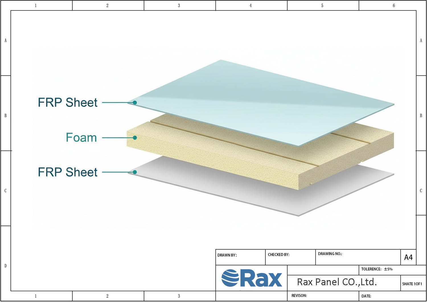
1: Understanding Structural Load Limits and Spans
SIP structural capacity is governed by panel thickness, core density, and facing material—span limits require engineered calculations, not rule-of-thumb assumptions.
Span Determination and Engineering Dependencies
Maximum roof spans are not a single fixed number. They are derived from the interaction of panel thickness, core material density, and facing gauge under specific load combinations. Residential roof systems commonly span up to 24 feet, while commercial applications with thicker panels and higher-density cores can reach 40 feet or more without internal support. These figures come from experimental testing per project-specific engineering standards, not generic tables.
Dimensional Lumber Chords vs. TSTUD Shear Capacity
A critical design decision involves how shear loads transfer at panel edges and joints. Traditional SIP installations rely on dimensional lumber chords—typically 2×6 or 2×8—embedded or nailed along panel boundaries to handle shear forces and provide nailing substrates for fixtures. TSTUD framing systems replace these lumber chords with engineered steel or composite channels that are integrated during panel fabrication.
- Dimensional lumber chords: Require on-site cutting, fastening, and sealing; introduce potential thermal bridges at chord locations if not details are carefully managed.
- TSTUD shear channels: Factory-integrated channels eliminate field-installed lumber at panel edges, maintain continuous thermal breaks, and provide consistent shear transfer paths that align with the panel’s structural diaphragm action.
Shear Wall and Seismic Considerations
Wall SIPs function as shear diaphragms, resisting lateral forces from wind and seismic activity. The shear capacity depends on panel thickness, core-to-facing bond integrity, and the quality of spline or channel connections at vertical joints. In high-seismic zones, engineers often specify thicker panels or reinforced connection details to meet code-required shear values. Panel manufacturers typically provide tested shear ratings, but these must be validated against the specific project’s load path requirements with a licensed structural engineer.
| Component | Structural_Function | Key_Specs | Primary_Benefit |
|---|---|---|---|
| Roof Systems | Monolithic I-Beam action (Skins act as flanges, Core acts as web) | Manufacturer engineering requirements specify a maximum clear span of 24 feet supported by spline reinforcement. Capable of R-40 thermal performance. | Enables cathedral ceilings and open floor plans; eliminates need for complex truss systems | “
| Wall Systems | Shear diaphragm and axial load resistance | Thicknesses ranging from 100mm to 250mm; Delivers up to R-25 thermal value | Eliminates thermal bridging; provides superior air tightness and seismic resistance |
| Material Matrix | Composite stress distribution | GRP or Steel facings bonded to Graphite-infused EPS or PET cores | Lightweight, high-strength, and moisture resistant; reduces foundation load requirements |
| Load Limits | Distributed load handling for Snow, Wind, and Live loads | Capacity determined by core density and facing gauge; Engineered via experimental testing to meet stringent project standards | High strength-to-weight ratio allows for lightweight, robust structures in extreme climates |
| Connection Integrity | Load transfer at panel joints and seams | Factory pre-cutting for windows, doors, and electrical chases; Requires specialized sealing and splines | Ensures structural continuity and thermal envelope integrity; prevents on-site modification errors |
2: Choose Core Materials for Thermal Performance
PET Foam vs. Graphite EPS: Real-World R-Value Comparison
Core conductivity is the primary lever for thermal performance in SIP assemblies. PET foam and graphite-enhanced EPS occupy adjacent performance tiers, but their real-world behavior diverges under sustained temperature differentials.
- PET Foam: Thermal conductivity of approximately 0.032 W/m·K, delivering an R-value of roughly R-5.0 per inch. A 6-inch PET core yields R-30, equating to a U-value near U-0.17 W/m²·K.
- Graphite EPS: Thermal conductivity of approximately 0.030–0.034 W/m·K, delivering R-5.0 to R-5.5 per inch. A 6-inch graphite EPS core yields R-30 to R-33, equating to a U-value of U-0.15 to U-0.17 W/m²·K.
PET foam maintains its R-value more consistently across temperature fluctuations, while graphite EPS offers a slight edge at standard conditions. Both outperform standard white EPS by 10–15% in thermal resistance.
Impact of Thermal Stud Integration on Thermal Bridging
Conventional wood or steel stud framing introduces thermal bridges that can degrade overall assembly performance by 15–25%. Integrating thermal breaks at framing junctions—where the panel meets vertical supports—eliminates these high-conductivity paths. This approach preserves the continuous insulation layer and allows the core material’s rated R-value to translate directly into wall performance, rather than being undermined by bridging at every bay.
3: Manage Moisture and Prevent OSB Decay
OSB decay is fundamentally a moisture management failure, not a panel defect. Rot begins when OSB moisture content exceeds 20% for sustained periods. The fix lies in controlling both liquid water intrusion and vapor diffusion at every interface.
Concrete Separation and Ground Contact
OSB is hygroscopic and will wick moisture from concrete foundations through capillary action. Building codes universally require a minimum 6-inch vertical separation between OSB sheathing and exposed concrete or masonry. Where this clearance cannot be maintained, a continuous damp-proof membrane or liquid-applied barrier must be installed between the panel edge and the foundation.
Managing Moisture Diffusion Through the Assembly
Effective moisture control protocols must account for the diffusion limits inherent in a tightly sealed envelope. In cold climates, interior vapor retarders (Class II or lower) are standard to limit driving diffusion into the foam core. In hot-humid climates, the strategy reverses: exterior-oriented assemblies with permeable weather barriers allow drying toward the outside.
- Exposed OSB edges: Every field-cut edge at electrical chases or joints must be sealed with a compatible vapor-retardant paint or tape before installation.
- Seam detailing: SIP seams are the most common moisture entry point. Properly flashed and gasketed seams prevent both bulk water and interior humidity migration.
- Stacking protocol: OSB-faced panels stored on-site must be elevated on pallets and fully wrapped with a breathable cover. Direct ground contact during storage is the leading cause of pre-installation decay claims.
4: Plan Factory Cuts and Electrical Chases
Electrical Chase Planning and Factory Pre-Cutting
The timing of electrical chase finalization is a critical bottleneck in SIP production. All chase locations must be confirmed on shop drawings before the manufacturing order is released, as post-fabrication modifications on-site compromise structural integrity.
Vertical cuts through the OSB facing for wiring runs are structurally acceptable and do not significantly affect load-bearing capacity. Horizontal cuts across the OSB face or through the core material, however, substantially reduce shear strength and must be avoided in panel design.
Factory-pre-cut chases are the preferred approach. When chase dimensions, outlet box locations, and switch placements are provided in production drawings, the factory can CNC-cut precise openings during manufacturing. This eliminates on-site cutting, preserves the continuous insulation envelope, and maintains the structural performance ratings validated during panel engineering.
- Chase width:Standard electrical chases are typically 1.5 to 2 inches wide, matching conventional 2×4 wall cavity dimensions.
- Outlet spacing:Outlet box openings should be spaced a minimum of 12 inches apart to maintain OSB web integrity between cuts.
- Timeline:Finalize all electrical layouts 10 to 14 days before the scheduled production start date to allow for drawing review and approval.
5: Connect SIPs to TSTUD Framing
Integrating SIPs with TSTUD Framing
Connecting Structural Insulated Panels (SIPs) to Thermal Stud (TSTUD) framing is essential for eliminating thermal bridges that compromise building envelope performance. Unlike traditional timber connections which act as conductive pathways, TSTUDs preserve the system’s R-value. For B2B contractors, the critical pain point is on-site modification; if panel edges do not align perfectly with TSTUD members, crews face excessive field trimming. This not only erodes profit margins through labor inefficiencies but also risks compromising the structural spline connections required for load transfer.
- Precision Layout: Coordinate wall dimensions with factory panel widths to ensure seams occur directly over the TSTUD web, eliminating the need for rip cuts.
- Load Distribution: Proper alignment ensures vertical loads are transferred through the panel skin into the TSTUD, maintaining structural integrity without relying on additional fasteners.
6: Best Practices for Footings and Assembly
Sill Plate Detailing and Concrete Separation
The panel-to-foundation junction is where most field failures originate. On a concrete slab, use a double bottom plate assembly: a foam sill seal gasket sits directly on the concrete, pressure-treated lumber is placed above it, and untreated lumber sits on top with the SIP panel bearing on the untreated layer. OSB facings must never contact concrete directly — capillary moisture migration through concrete is continuous and irreversible over the building lifecycle.
Spline and Panel Joint Connections
Spline connections transfer lateral loads between adjacent SIP panels and maintain diaphragm continuity. Matched tongue-and-groove splines, typically routed from the panel’s core material, should be glued and screwed at the manufacturer-recommended spacing. Misaligned splines create air gaps that compromise both structural integrity and thermal performance. Always verify full spline engagement before applying adhesive.
On-Site Assembly Protocols
Coordinate panel delivery so the foundation is complete immediately before panels arrive. Stack panels high, dry, and flat, organized in erection sequence to minimize handling. Weather protection with tarpaulin coverage is essential during any delay. Damaged panels must be rejected at the dock; field repairs at the foundation interface are far costlier than pre-installation inspection.
7: Air Sealing for Code Compliance
Air sealing is the single most critical performance variable in SIP construction—panel R-value means nothing if the air barrier leaks at every joint.
Continuous Spline Sealing Strategy
The spline joint—where two SIP panels meet edge-to-edge—requires a continuous bead of low-expansion foam sealant applied to the spline groove before panel engagement. This foam compresses during assembly, filling micro-gaps that tape alone cannot bridge. The sealant must remain fully compressed after panel mating to maintain an unbroken air barrier.
Advanced Tape Application Techniques
High-performance SIP tape serves as the secondary air barrier over the spline joint. Key application requirements include:
- Surface Prep: OSB facing must be clean, dry, and free of dust or release agents before tape adhesion.
- Seam Contact: Tape must overlap each panel face by a minimum of 50mm, with full conformal contact across the entire spline length.
- Temperature Window: Tape installation is only reliable between 5°C and 35°C; adhesive activation fails below this range.
Code Compliance Outcomes
When spline sealant and tape are applied per manufacturer specifications, SIP structures consistently exceed T24 compliance standards for air leakage. Properly sealed SIP assemblies typically achieve air change rates below 0.3 ACH@50Pa, well within the thresholds required by IECC 2021 and 2024 energy codes for commercial and residential applications.
Conclusion
Every wall assembly we’ve reviewed in this article shares one reality — thermal bridging and air leakage don’t negotiate. When SIP panels meet TSTUD framing, the connection point becomes the weakest link if left unaddressed. We’ve seen projects stall because span calculations ignored core material compression, or moisture traps formed where OSB met unsealed joints. The panels carry the load, but the details carry the performance.
- Verify your span tables against actual load requirements before ordering panels.
- Confirm core material selections match your climate zone and moisture exposure.
- Request engineering review from our team when integrating SIPs with TSTUD systems — we handle hundreds of custom connections annually and spot design gaps early.
- Plan electrical chases and factory cuts on paper first, not on the job site.
Frequently Asked Questions
How do SIPs prevent thermal bridging?
SIPs eliminate thermal bridging because the continuous foam core runs the full depth of the panel, unlike conventional stick framing where wood or steel studs create conductive pathways. This uninterrupted insulation layer significantly reduces heat loss through the wall assembly. The result is a more consistent thermal envelope with fewer cold spots and lower energy bills over the building’s lifetime.
What facing materials are available for SIP panels?
Common facings include GRP/FRP with gelcoat, CFRT sheets, aluminum, steel, stainless steel, ACP, plywood, and PVC. Each facing offers different strengths: GRP provides corrosion resistance and waterproofing, steel delivers high impact strength, and aluminum offers lightweight durability. The facing choice affects structural capacity, finish requirements, and compatibility with the project’s aesthetic and performance goals.
How do SIPs compare structurally to TSTUD framing?
SIPs act as both structure and enclosure, distributing loads across the entire panel surface rather than concentrating them at individual studs. TSTUD framing provides a traditional stud-based framework that SIPs connect to at transitions or openings. Together, they combine the speed and insulation continuity of SIPs with the flexibility of conventional framing where needed, such as at foundations or complex architectural details.
Are SIPs suitable for both walls and roofs?
Yes, SIPs are engineered for both vertical and horizontal applications, though specifications differ. Roof panels typically require higher load ratings and may use thicker cores or stronger facings like GRP or steel to handle dead and live loads. Wall panels prioritize thermal performance and air tightness. A manufacturer should provide structural calculations for each application.
Can SIPs be modified on-site after delivery?
Minor field modifications are possible, but they should be approached with caution. Cutting into the core or facing compromises structural integrity and thermal continuity unless properly sealed and reinforced. RaxPanel pre-cuts windows, doors, and electrical chases at the factory to avoid this risk entirely. Any on-site alterations must follow the engineer’s specifications and be resealed to maintain air and moisture barriers.
What fire ratings do SIP panels carry?
SIP fire performance depends on the core and facing materials selected. Standard EPS cores can be formulated with fire retardants, while PIR and mineral wool cores offer inherently higher fire resistance. Facings such as GRP with gelcoat or steel also contribute to the assembly’s fire rating. Builders should verify the specific UL or equivalent rating for the panel configuration specified in their project plans.
What are the cost trade-offs versus conventional framing?
SIPs carry a higher upfront material cost than traditional wood-frame construction, but they often offset this through faster installation, reduced labor hours, and lower long-term energy costs. The elimination of separate insulation, vapor barriers, and air sealing materials also compresses the overall assembly cost. For commercial and high-performance residential projects, the total installed cost can be competitive when all factors are considered.