
Thermal bridging and air leakage rarely occur in the center of a panel; they happen at the joints. That connection point is the single most critical variable in determining whether a facility maintains thermal efficiency or fails regulatory hygiene standards. While insulated metal panels (IMPs) are often used for longer spans, our experience at RaxPanel shows that cam lock panels provide greater flexibility in layout and configuration, making them essential for complex modular designs that fixed-span systems cannot support.
We examine the eccentric cam mechanism and interlocking edge geometry required for precise structural alignment, alongside the compression forces necessary for airtight sealing. You will learn to verify specific fitment tolerances and gasket compression set resistance, ensuring your specifications eliminate the seam leaks that drive up energy costs.
How Core Components Ensure Structural Alignment
Structural alignment is achieved through the synergy of three engineered systems: the eccentric rotational force of the cam lever, the physical registry provided by interlocking edges, and the composite rigidity ensured by core-to-skin adhesion.
Cam Lever Mechanism and Rotational Engagement
The core of the alignment system lies in the eccentric action of the cam lever. Unlike simple bolted connections, the cam lock converts rotational torque into significant linear pulling force. As the operator rotates the cam arm typically 180 degrees, the eccentric profile of the cam housing engages with the head of the cam bolt inserted into the adjacent panel. This action draws the two panels together rapidly, often without the need for specialized tools.
Precision is critical in this engagement. The system relies on the interaction between a bolt—typically cylindrical with a diameter of 5mm or 6mm—and the receiving cam housing. For the mechanism to function correctly, the centerline of the bolt hole must align perfectly with the center of the cam housing. Industry tolerances are tight; even a misalignment of 2mm can prevent the cam from engaging or force the joint into an angular bind, compromising the structural integrity of the wall. Therefore, manufacturing consistency in hole placement is a primary determinant of field alignment success.
Interlocking Panel Edge Geometry
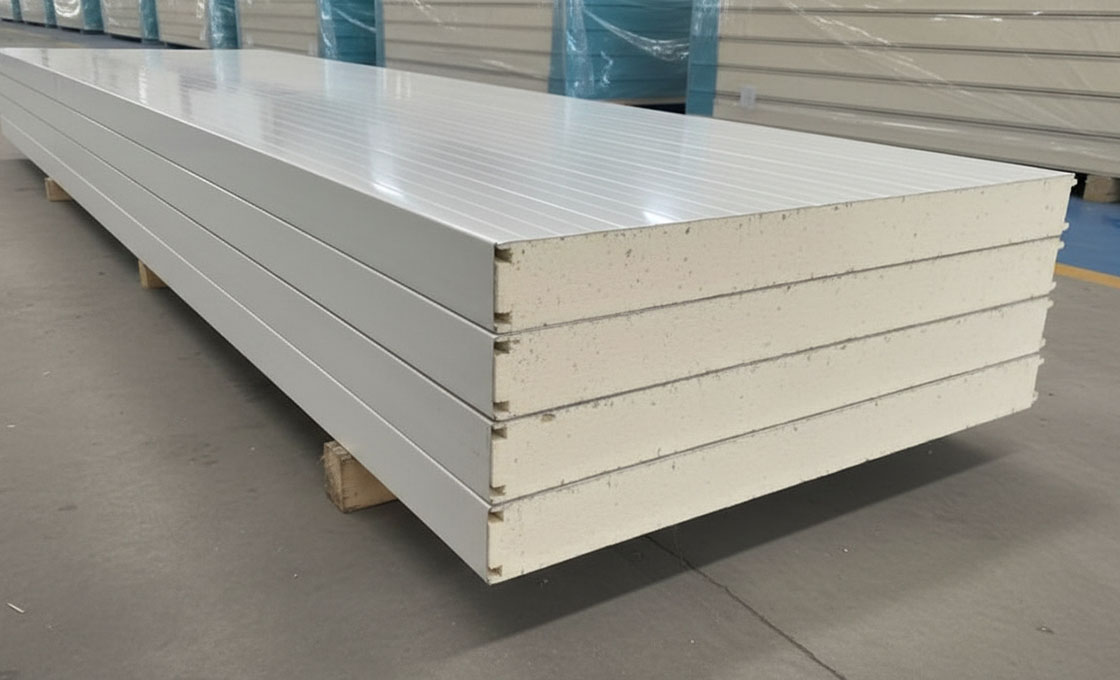
Before the cam lever is even rotated, the physical geometry of the panel edges dictates initial alignment. High-performance cam lock panels utilize specific edge profiles—such as stepped joints or tongue-and-groove configurations—that act as mechanical guides during installation. These interlocking features ensure that the panels are vertically and laterally registered as they are brought together.
This geometry serves two functions: it resists shear loads once the panels are locked, and it prevents the panels from slipping out of plane during the installation process. By physically constraining the movement of the adjacent facings, the edge geometry eliminates the “play” that can occur in flat-to-flat joints, ensuring that when the cam lever is engaged, the panels are already in their optimal structural position.
Foam-in-Place Manufacturing and Core-to-Skin Bonding
The mechanical strength provided by the cam and edge geometry is only effective if the panel itself acts as a rigid composite body. This rigidity is achieved through high-quality foam-in-place manufacturing, where the polyurethane or polyisocyanurate core is injected between the metal facings and expands to fill the entire cavity.
The critical factor here is the core-to-skin bond. The foam must chemically adhere to both the interior and exterior metal sheets to create a monolithic structural sandwich (Structural Insulated Panel behavior). If this bond is weak or if voids exist within the core, the metal skin may deflect or delaminate when the cam lever applies tension. A strong, void-free bond ensures that the pulling force exerted by the cam is distributed evenly across the panel surface, maintaining dimensional stability and preventing local deformation that could misalign the joint over time.

How Materials Affect Panel Longevity and Compliance
Material selection is the single largest variable in Total Cost of Ownership (TCO). While facing materials dictate corrosion resistance and hygiene compliance, core chemistry (PU vs. PIR) determines fire safety classification and long-term thermal stability. Choosing generic facings or cores to save upfront capital often results in premature failure and regulatory violations.
Galvanized Steel vs. Stainless Steel (304) Facings
In the B2B procurement of composite panels, the choice between Galvanized (GI) and Stainless Steel (SS 304) facings is rarely just about the purchase price; it is a calculation of environmental aggression versus lifecycle cost. Galvanized steel, typically coated with a layer of zinc, offers a lower entry price and adequate protection for dry storage or controlled environments with low humidity. However, in our 15 years of manufacturing and exporting to over 50 countries, we have observed that GI facings suffer from “white rust” and rapid oxidation in coastal or high-chloride environments.
For facilities involving food processing, pharmaceuticals, or frequent washdowns, Stainless Steel 304 is non-negotiable. Unlike GI, where a scratch exposes the underlying steel to rust, 304 SS is a homogeneous alloy that resists chlorides and organic acids found in sanitizers. From a compliance standpoint, regulations such as HACCP and FDA standards explicitly require surfaces that are non-corroding, non-toxic, and easily cleanable—standards that generic galvanized steel struggles to meet over a 5-year cycle.
Neoprene vs. Silicone Gasket Performance
The gasket is the Achilles’ heel of any CamLock or tongue-and-groove system. It creates the airtight seal, and its degradation is the primary cause of energy loss in panel joints. Neoprene (Polychloroprene) has been the industry standard for decades due to its good oil and weather resistance and lower cost. However, Neoprene has a narrower effective temperature range and tends to harden and lose compression set resistance when exposed to extreme sub-zero cycles over long periods.
Silicone rubber offers superior performance in applications with wide temperature fluctuations (-60°C to +230°C). In our laboratory testing, silicone gaskets maintain elasticity significantly longer than Neoprene in deep-freeze environments (-30°C and below). This prevents the “shrink-back” effect where the gasket pulls away from the joint, creating thermal bridges. While Silicone is a higher upfront investment, the extended maintenance interval—typically requiring inspection every 12 months rather than 6—justifies the cost for high-value cold storage and hygiene-critical cleanrooms.
PU vs. PIR Core: Thermal Efficiency and Fire Compliance
The distinction between Polyurethane (PU) and Polyisocyanurate (PIR) cores is critical for fire safety compliance, yet it is often misunderstood. Visually, they are nearly identical, but chemically, PIR is a modified thermoset plastic designed for enhanced fire resistance. Under intense heat, standard PU foam will melt, drip, and contribute to fueling a fire. PIR, conversely, undergoes a chemical reaction when exposed to flame: it chars to form a protective carbon layer (intumescence) that self-extinguishes once the ignition source is removed.
This chemical difference dictates compliance with building codes such as EN 13501-1. PIR typically achieves a Class B1 or better fire rating, whereas standard PU often caps at Class B2 or C. For commercial warehouses and public buildings, insurance underwriters and local fire marshals frequently mandate PIR or non-combustible cores like Rockwool. Thermally, PIR also holds a slight edge; it exhibits better dimensional stability at higher temperatures, helping the panel retain its R-value (thermal resistance) over a 25-year service life compared to standard PU.
- Fire Behavior: PIR chars and resists flame spread (self-extinguishing); PU can melt and drip.
- Thermal Stability: PIR maintains structural integrity and insulation value at higher surface temperatures.
- Regulatory Compliance: PIR is the minimum requirement for most modern commercial building codes (Class B1).
| Component Type | Material / System | Key Specification 1 | Key Specification 2 | Longevity Factor |
|---|---|---|---|---|
| Core Material | PU Foam | 0.020–0.028 W/mK (Thermal Conductivity) | B1/B2 (EN 13501-1) | Excellent thermal retention; resistant to moisture absorption; 25+ year service life |
| Core Material | PIR Foam | 0.022–0.026 W/mK (Thermal Conductivity) | B1 (EN 13501-1) | Higher fire resistance and thermal stability; maintains R-value under prolonged heat exposure |
| Core Material | Rockwool | 0.032–0.040 W/mK (Thermal Conductivity) | A1 (Non-combustible) | Inherently fireproof and hydrophobic; does not degrade at high temperatures; longest fire-safe lifespan |
| Core Material | XPS Foam | 0.029–0.035 W/mK (Thermal Conductivity) | B2 (EN 13501-1) | Closed-cell structure provides high compressive strength and moisture resistance; ideal for flooring and roof panels |
| Core Material | PET Foam | 0.035–0.045 W/mK (Thermal Conductivity) | B1 (EN 13501-1) | Recyclable thermoplastic core; retains structural integrity under cyclic thermal loading; eco-friendly lifecycle |
| Facing Material | Stainless Steel (304) | Excellent (Marine/Acid Resistant) | FDA/USDA Compliant, ESD-Safe Options Available | Resists rust and chemical degradation; ideal for seafood processing and pharma environments |
| Facing Material | Aluminum / Aluzinc | Good (Aluzinc superior in humid climates) | Lightest facing option; reduces structural load | Aluzinc offers 2–3× longer lifespan vs. standard aluminum in coastal environments |
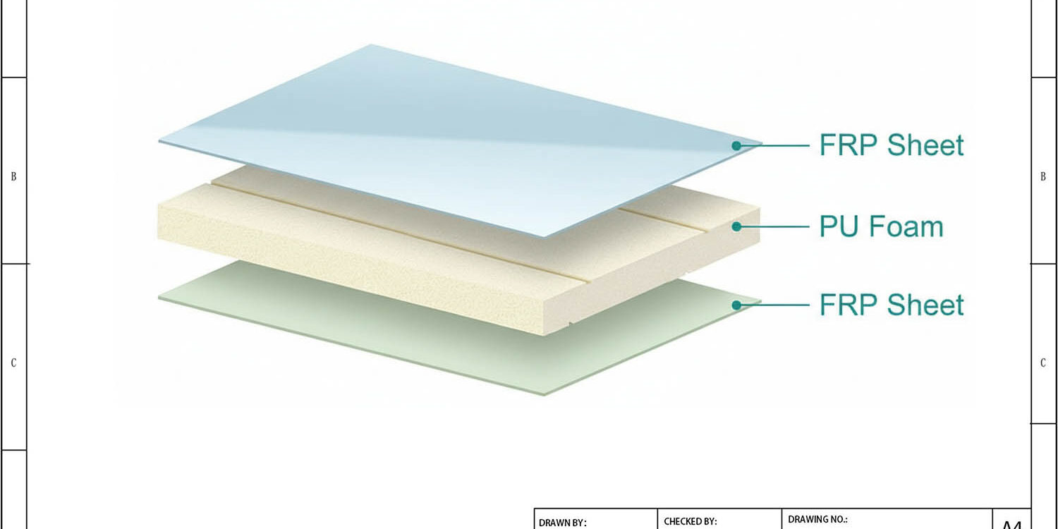
| Facing Material | GRP/FRP (with Gelcoat) | High (Chemical and UV Resistant) | Smooth, gelcoat-sealed; easy to clean | Gelcoat layer prevents water ingress and fiber degradation; 20+ year outdoor lifespan |
| Joint System | CamLock | Built-in metal lock + rubber gasket | 10–20% lower R-value at joints vs. panel center | Gasket compression degrades over 5–8 years; requires torque inspection every 6 months |
| Joint System | Tongue-and-Groove | Full-edge continuous contact seal | Minimal thermal bridge; near-center-panel R-value maintained | Superior long-term stability; 10–15% lower energy loss over 10-year lifecycle vs. CamLock |
| Environmental Factor | Temperature Range | -45°C to ambient (PU/PIR cores) | PU/PIR stable; Rockwool unaffected; XPS may soften above 70°C | Core selection must match operational temperature to prevent permanent deformation |
| Environmental Factor | Humidity / Corrosion | High risk in marine, seafood, and chemical environments | Recommended Facing: 304 Stainless Steel or Aluzinc; avoid standard galvanized steel | Corrosion-resistant facings extend panel lifespan by 2–3× in aggressive environments |
How Cam Compression Creates Airtight Seals
Cam compression seals rely on mechanical clamping force to deform elastomeric gaskets into panel joints, creating pressure-rated airtight barriers that maintain cold room integrity across thousands of installation and maintenance cycles.
Cam-Induced Compression Force and Gasket Deformation
The airtight seal in a CamLock panel system is generated through a precisely engineered mechanical compression process. When the cam lever is rotated, the eccentric cam profile converts rotational input into linear downward clamping force along the panel edge. This force compresses the elastomeric gasket—typically neoprene or silicone—positioned within the tongue-and-groove channel between adjacent panels.
Gasket deformation follows a predictable stress-strain curve. Effective sealing typically requires 20% to 35% compression of the gasket’s original cross-section. At this deflection range, the elastomer flows into microscopic surface irregularities on both the tongue and groove faces, eliminating air pathways that would otherwise permit thermal leakage. The tongue-and-groove interlock serves a dual function: it guides panel alignment during installation and provides a confined chamber that directs compression force uniformly across the gasket perimeter.
The mechanical advantage of the cam lever determines the achievable clamping force. A well-designed cam mechanism delivers consistent compression regardless of operator torque input, which is critical for maintaining seal uniformity across long panel runs. Insufficient cam travel or lever ratio results in under-compressed gaskets with visible gaps. Over-compression, conversely, can exceed the gasket’s elastic limit and cause permanent material failure.
Airtight Seal Pressure Ratings for Positive and Negative Environments
Cold storage and clean room applications subject panel joints to two distinct pressure regimes. Positive pressure environments maintain internal air pressure above ambient, typically to prevent unfiltered warm air infiltration through joint gaps. Negative pressure environments operate below ambient pressure, creating inward suction forces that test the seal’s resistance to air pull-through.
Properly compressed CamLock panel joints achieve the following pressure differential ratings:
- Standard cold storage applications: 50 to 150 Pa pressure differential resistance across sealed joints, sufficient for most refrigerated warehouse and processing environments operating between -25°C and +10°C.
- High-performance sealed installations: 200 to 300 Pa resistance achievable with silicone gaskets and precision-manufactured panel edges, required for deep-freeze applications at -40°C and below.
- Negative pressure tolerance: Sealed joints must resist inward air infiltration without gasket lift-off or edge separation. Silicone gaskets generally outperform neoprene in sustained negative pressure due to lower compression set and better low-temperature flexibility.
Pressure rating validation typically follows ASTM E283 or EN 12114 test methodologies for air permeability of building components. Joint performance degrades when cam compression is uneven—commonly caused by panel edge warpage, gasket misalignment, or insufficient lever engagement. Field verification using smoke pencil or differential pressure gauges remains the most reliable method for confirming seal integrity after installation.
Gasket Compression Set Resistance Over Cycle Life
Compression set measures the permanent deformation that remains in a gasket after it is compressed for an extended period and then released. It is expressed as a percentage of the original compressed thickness. A lower compression set percentage indicates superior elastic recovery and longer seal life—critical for CamLock systems that undergo repeated installation, maintenance access, and thermal cycling.
Elastomer selection directly determines compression set performance:
- Neoprene (CR) gaskets: Typically exhibit compression set values of 15% to 25% after 22 hours at 70°C per ASTM D395 Method B. Adequate for standard cold storage where thermal cycling is moderate and maintenance access is infrequent.
- Silicone (VMQ) gaskets: Silicone gaskets outperform neoprene in compression set resistance, recording values between 10% and 15% under ASTM D395 testing.
- EPDM gaskets: Offer compression set resistance between 12% and 20%, with strong resistance to ozone and weathering, making them suitable for applications with periodic washdown exposure.
Cycle life in CamLock systems is defined by repeated cam engagement and disengagement during panel installation and future maintenance access. Each compression-release cycle imposes elastic strain on the gasket. Over thousands of cycles, cumulative microstructural fatigue leads to gradual compression set accumulation. Panels in continuous-service cold storage environments—where gaskets remain compressed for years without disassembly—typically maintain seal integrity for 15 to 25 years when silicone or high-grade neoprene gaskets are specified.
Extended cold-storage service exposes gasket materials to cumulative compression set that varies significantly by elastomer type. In continuous-service applications requiring a 15–25 year life, the material must resist this permanent deformation to ensure seal integrity. Silicone maintains flexibility down to -50°C or lower, making it the preferred choice for deep-freeze and cryogenic storage environments where reliability cannot be compromised.
Designing Panels for Food Processing Washdowns
Surface Finish and Cleanability Requirements
Food processing facilities demand panel surfaces that resist bacterial harborage and withstand aggressive cleaning cycles. The facing material must achieve a smooth, non-porous finish rated for high-pressure washdown environments. Stainless steel facings, particularly grade 304 or 316, are the industry standard for areas exposed to direct spray and caustic chemical cleaning. These grades resist pitting corrosion from chlorinated cleaners and alkaline detergents commonly used in food-grade sanitation protocols.
When stainless steel facings are not cost-effective for the entire installation, gelcoated GRP panels offer a viable alternative for less aggressive washdown zones. The gelcoat layer provides a chemically resistant, easily cleanable surface that meets FDA 21 CFR requirements for food contact surfaces. However, gelcoat performance degrades under repeated high-pressure exposure, typically requiring resurfacing or replacement within 5 to 7 years in heavy washdown conditions.
Surface roughness specifications should target a finish below 0.8 micrometers Ra to ensure effective cleaning validation. Panels with textured or embossed facings create microscopic crevices where biofilm can establish, creating compliance risks during USDA and HACCP audits.
Edge and Joint Design for Washdown Exposure
The CamLock interlocking edge geometry must incorporate sealed gasket channels that prevent washdown water infiltration into the panel core. During high-pressure cleaning cycles, water can reach pressures of 1,000 to 1,500 PSI, forcing moisture into any unsealed joint gap. The cam lever mechanism compresses the neoprene or silicone gasket to create a continuous seal along the entire panel edge, blocking water ingress at the joint interface.
For food processing facilities operating under continuous washdown conditions, panel joints should be oriented to minimize horizontal seams where water can accumulate. Vertical joint configurations with overlapping gasket channels direct washdown water away from the sealed interface rather than allowing it to pool at the panel connection point.
Gasket Material Selection for Chemical and Thermal Cycling
- Silicone Gaskets: Offer superior resistance to caustic cleaning chemicals and maintain elasticity across a broader temperature range from -40°C to 200°C. Ideal for facilities using steam cleaning or high-temperature washdown protocols.
- Neoprene Gaskets: Provide good chemical resistance at a lower cost point but begin to degrade under repeated exposure to strong alkaline solutions above pH 12. Suitable for general food processing environments with standard cleaning regimes.
Gasket compression set resistance is a critical specification for washdown applications. Quality gaskets should maintain at least 75% of their original compression force after 500 thermal cycles between -20°C and 60°C. Gaskets that lose compression elasticity create joint gaps where washdown water and contaminants penetrate, leading to core saturation and panel delamination over time.
Core Material Performance Under Moisture Exposure
Polyurethane foam cores demonstrate lower water absorption rates compared to polystyrene variants, making PU the preferred choice for washdown environments. Closed-cell PU foam with water absorption below 1.5% by volume maintains structural integrity even when joint seals experience minor moisture exposure during cleaning cycles.
In facilities with frequent freeze-thaw cycles or where panel surfaces are subjected to direct high-pressure water streams, PU cores with density ratings of 40 to 45 kg/m³ provide the optimal balance of thermal performance and moisture resistance. Lower-density cores increase the risk of water migration through the foam matrix if any joint seal compromise occurs.
Regulatory Compliance and Certification Standards
Panel systems installed in food processing washdown zones must comply with applicable regulatory frameworks including FDA 21 CFR for food contact surface materials, USDA sanitary design requirements, and EHEDG guidelines for hygienic equipment design. These standards address material safety, surface cleanability, joint design, and resistance to cleaning chemical degradation.
Manufacturers should provide documentation confirming that panel facings, adhesives, and gasket materials meet the relevant food-safe certifications. Third-party testing to standards such as NSF/ANSI 2 for food equipment materials adds credibility and simplifies the facility’s compliance audit process with regulatory inspectors.
Reinforcing Panels for High-Traffic Warehouses
In high-traffic logistics hubs, standard panel configurations fail under repetitive impact. Reinforced zones utilizing stainless steel or GRP facings combined with high-density cores are essential to prevent penetration and thermal failure.
The Physics of Impact in Distribution Centers
High-traffic warehouses face a relentless assault from material handling equipment (MHE). Standard insulated panels, often designed with light-gauge galvanized steel skins, are susceptible to puncture and deformation when struck by forklifts or pallet jacks. This compromises not only the structural integrity of the wall but also the thermal envelope, leading to significant energy loss and potential condensation issues. To mitigate this, engineering specifications for distribution centers must prioritize puncture resistance and energy absorption over mere insulation value in lower wall zones—typically the bottom 1 to 1.5 meters where impacts occur most frequently.
Advanced Facing Materials for Impact Zones
While standard pre-painted steel is cost-effective for the majority of the building envelope, reinforced panels require specialized facings. Manufacturers increasingly utilize Stainless Steel Sandwich Panels or Glassfiber Reinforced Polymer (GRP/FRP) Sandwich Panels in these critical zones.
Stainless steel facings provide superior hardness and puncture resistance compared to galvanized steel, effectively resisting “swipe” damage from heavy loads. Alternatively, GRP facings offer a unique combination of high tensile strength and resilience. Unlike metal, which may permanently dent, FRP composites exhibit elastic properties that can absorb kinetic energy without permanent deformation, making them ideal for high-velocity impact areas.
| Facing Material | Impact Resistance | Durability Profile |
|---|---|---|
| Stainless Steel | High; resists puncture and deep scratches. | Exceptional corrosion resistance; maintains surface hygiene. |
| GRP / FRP | High Energy Absorption; resists cracking. | Rust-proof; lighter than steel equivalents. |
| Reinforced Aluminum | Medium; prone to denting without backing. | Lightweight; requires protective rails for high-traffic use. |
Core Density and Structural Support
The core material plays a pivotal role in the panel’s ability to withstand blunt force. While standard PU (Polyurethane) or PIR foam provides excellent thermal insulation, high-traffic applications benefit from higher density foam formulations or structural cores. Honeycomb panels, particularly those utilizing PP or fiberglass honeycomb cores, offer superior rigidity and compressive strength compared to pure foam cores. When composited with fiberglass sheets, these honeycomb structures distribute impact loads across a wider surface area, preventing localized failure. For extreme environments, incorporating plywood or balsa cores within GRP sandwich panels can significantly increase the screw-holding force and resistance to localized impacts, ensuring that wall anchors and fixtures remain secure even after collisions.
Leveraging Transportation-Grade Engineering
The rigorous demands of vehicle manufacturing provide a reliable benchmark for warehouse reinforcement. Composite materials engineered for refrigerated truck bodies and dry freight boxes are subjected to constant vibration and road impact—conditions that parallel the mechanical stress of a busy warehouse floor. By specifying truck-grade composite panels, such as those utilizing CFRT (Continuous Fiber Reinforced Thermoplastic) or multi-layer foam cores, facility managers can ensure their wall systems possess the same fatigue resistance and durability found in heavy-duty transport logistics. These advanced composites are often lighter and thinner than traditional alternatives while maintaining higher strength-to-weight ratios, allowing for robust reinforcement without adding excessive dead load to the building structure.
Ensuring Fire Safety in Hazardous Environments
In hazardous industrial settings, fire safety hinges on two factors: the core material’s inherent fire rating and the joint system’s ability to maintain integrity under thermal stress. Cam lock panels address both through specialized core selection and engineered compression sealing.
Core Material Selection for Fire Compliance
Core material selection dictates fire performance in CamLock panel systems, especially where ignition risk is elevated. For chemical storage, processing facilities, or areas with flammable vapors, the core must meet strict fire classification standards, with two primary options standing out for hazardous applications: PIR and rockwool.
PIR foam’s char-forming behavior under thermal exposure sets it apart from PU’s tendency to melt and drip. PIR panels typically achieve Class 1 fire ratings under UK classification systems and can meet ASTM E84 requirements for surface burning characteristics when properly manufactured. While these panels offer a strong balance of fire performance and thermal efficiency, they remain combustible and are therefore not suitable for applications demanding non-combustible performance.
For applications demanding non-combustible performance, rockwool sandwich panels provide the highest level of fire protection. Rockwool is inherently non-combustible with a melting point exceeding 1000°C, making it suitable for the most stringent fire safety codes. These panels are commonly specified for pharmaceutical cleanrooms, semiconductor facilities, and industrial spaces handling combustible materials.
- PIR Core: Self-extinguishing, low smoke density, typically achieves 1-hour fire resistance ratings at 50mm thickness
- PU Core: Requires fire-retardant additives to meet basic code requirements; higher smoke development than PIR
- XPS/PVC Cores: Limited fire performance; generally unsuitable for hazardous environment applications without specialized facings
Joint Design and Flame Spread Prevention
Even the best fire-rated core material can fail if the panel joint system allows flame or hot gas penetration. Cam lock panel joints are specifically engineered to minimize this risk through three key design features.
First, the cam lever mechanism creates a compression seal that eliminates the gaps where flames and smoke could travel between panels. When the cam is engaged, it compresses the neoprene or silicone gasket to fill the entire joint cavity, leaving no unsealed pathway for fire propagation.
Second, the interlocking edge geometry provides a labyrinth-style barrier. Even if the gasket were compromised by extreme heat, the overlapping metal edges and foam core create a physical path that flame must traverse, significantly slowing spread compared to simpler tongue-and-groove or butt-joint systems.
Third, the foam-in-place manufacturing process ensures the core material bonds continuously across the full panel width without voids or delamination at the edges. Gaps between the core and facing materials are common failure points in fire scenarios, as they create hidden channels for flame travel behind the visible surface.
Facing Material Considerations
The panel facing contributes to overall fire safety in ways that extend beyond the core. In hazardous environments, facings must resist ignition, limit flame spread, and maintain structural integrity during fire exposure.
Stainless steel facings offer the highest fire resistance among common panel materials. They do not combust, have minimal thermal expansion, and maintain strength at temperatures that would soften aluminum or degrade composite facings. For food processing and pharmaceutical facilities with washdown requirements, stainless steel cam lock wall panels provide both fire safety and hygiene compliance.
Galvanized steel facings are a cost-effective alternative that still provides excellent fire performance. The zinc coating offers corrosion resistance while the steel substrate maintains structural integrity during fire events. However, in high-temperature industrial settings, galvanized facings may lose their protective coating faster than stainless steel variants.
- Stainless Steel Facing: Non-combustible, corrosion-resistant, ideal for chemical and pharmaceutical hazardous zones
- Galvanized Steel Facing: Non-combustible substrate with cost-effective corrosion protection; suitable for general industrial applications
- Aluminum Facing: Non-combustible but lower melting point (~660°C); may lose structural integrity in intense fire conditions
- GRP/FRP Facing: Thermoset variants offer better fire resistance than thermoplastics; gelcoat surfaces can be formulated for flame spread compliance
Meeting Code Requirements in Hazardous Zones
Different hazardous environments are governed by distinct fire codes and classification systems. Understanding these requirements is essential for proper panel specification.
In the United States, the International Building Code (IBC) and NFPA standards dictate fire resistance ratings based on occupancy type and hazard classification. Industrial facilities storing flammable liquids may require 1-hour or 2-hour fire-rated wall assemblies, which directly influences core thickness and facing selection.
European installations follow EN standards, where fire performance is classified under EN 13501-1. The classification system ranges from A1 (non-combustible, typically rockwool cores) through to F (no performance determined). Cam lock panels with PIR cores typically achieve B-s1,d0 or C-s1,d0 classifications, while rockwool variants can reach A2-s1,d0.
For cleanroom applications in hazardous pharmaceutical or semiconductor environments, additional requirements around smoke density and toxic gas emission during fire events apply. PIR cores produce significantly lower smoke densities compared to PU variants, and rockwool produces virtually no toxic emissions when exposed to fire.
Thermal Expansion and Joint Integrity Under Fire Conditions
One of the most overlooked aspects of fire safety in cam lock panel systems is how thermal expansion affects joint integrity during a fire event. As temperatures rise, different materials expand at different rates, potentially breaking the seal that the cam lock mechanism provides under normal conditions.
Steel facings expand at approximately 12 micrometers per meter per degree Celsius, while polymer foam cores expand at significantly higher rates. This differential expansion can create stress at the facing-to-core bond line. High-quality panels manufactured with proper adhesive selection and foam density control (typically 40-45 kg/m³ for PU/PIR cores) maintain bond integrity better under thermal cycling than lower-density alternatives.
The cam lock mechanism itself offers an advantage here compared to fixed-joint systems. Because the cam lever allows for slight rotational adjustment during engagement, it can accommodate minor dimensional changes caused by thermal expansion without losing compression on the gasket. This self-adjusting characteristic helps maintain the fire seal longer during the early stages of a fire event.
Specification Checklist for Hazardous Environment Applications
When procuring cam lock panels for hazardous environments, buyers should verify the following technical parameters to ensure fire safety compliance:
📋 Actionable Steps
- Step 1: Identify the applicable fire code for your jurisdiction (IBC, EN 13501-1, BS 476, or local equivalent) and the required fire resistance rating for your specific hazard classification.
- Step 2: Select core material based on fire rating requirements—PIR for Class 1 / EN B-s1,d0 applications, rockwool for non-combustible / EN A2-s1,d0 requirements.
- Step 3: Verify facing material compatibility with both fire safety and environmental conditions (corrosion, washdown, chemical exposure).
- Step 4: Request third-party test certificates for the complete panel assembly, not just individual component ratings. Confirm tests were conducted per the relevant standard.
- Step 5: Confirm gasket material specifications—neoprene gaskets typically withstand temperatures up to 120°C continuously, while silicone variants handle up to 200°C, which matters for fire scenario performance.
- Step 6: Validate that the cam lock joint design has been evaluated for fire integrity, including resistance to joint separation under thermal expansion conditions.
Fire safety in hazardous environments is not determined by a single component but by the integrated performance of core material, facing selection, joint design, and gasket integrity. Cam lock panel systems, when specified correctly with fire-rated cores and appropriate facing materials, provide a reliable solution that meets the most demanding industrial fire safety codes while maintaining the airtight seal performance that these environments require.
Designing Modular Layouts for Controlled Environments
Effective modular layout design relies on aligning the panel grid system with the required airflow dynamics and ISO classification of the controlled environment.
Structural Alignment with ISO Classification Standards
Designing modular layouts for pharmaceutical and technology cleanrooms begins with matching panel specifications to the required ISO classification. A Class 1000 (ISO 7) environment demands different joint tolerances and panel thickness profiles than a Class 100 (ISO 5) space. The modular nature of CamLock panel systems allows layouts to be planned around these classification boundaries. However, the precision engineering required for these environments means the layout cannot be treated as a simple grid; it must account for the cumulative deflection of the wall and ceiling spans to prevent gaps that compromise the cleanroom envelope. For high-precision environments, the design phase must prioritize the reduction of thermal bridging at panel intersections to maintain uniform temperature stability, which is critical for both process validation and energy efficiency.
Optimizing Ceiling Grids for Airflow Efficiency
In controlled environments, the ceiling is often the most active component of the layout. The placement of Fan Filter Units (FFUs) and lighting modules dictates the modular grid. A common failure point in layout design is allowing panel joints to interfere with laminar flow. The design must ensure that the ceiling module width—typically 1150mm to 1200mm—aligns perfectly with the lighting troughs and FFU cutouts to minimize turbulence.
- FFU Integration: Ceiling panels should be pre-engineered with stiffeners to support the weight of heavy filter units without sagging, which creates cracks in the gelcoat or surface finish.
- Laminar Flow Paths: Layouts for unidirectional flow (cleanrooms) must minimize horizontal seams in the airflow path. Vertical wall-to-ceiling transitions must utilize radius corner modules to eliminate 90-degree angles where particulates accumulate.
- Return Air Grilles: The floor layout must position low-wall return air grilles to create a “plug flow” effect, ensuring air sweeps across the process area rather than short-circuiting to the return.
Strategic Zoning for Pressure Cascades
Achieving pressure cascades—moving from clean to less clean areas—requires the layout to incorporate airlocks and buffer zones effectively. The layout design must account for the volume of air required to maintain these pressure differentials (typically 15-20 Pa between corridors and cleanrooms). Simply adding an airlock chamber is insufficient; the layout must define the specific swing direction of doors to assist pressure push rather than fight it. additionally, the modular layout should segregate services to prevent cross-contamination between different pressure zones. For instance, piping and electrical conduits should not pass directly through a wall separating an ISO 5 suite from an ISO 8 corridor without proper sealed bulkheads.
When designing complex modular layouts, avoid field-modifying standard panels. Engaging manufacturers that offer end-to-end design solutions allows for the production of custom-sized composite panels that fit the architectural drawing perfectly. This reduces on-site cutting, which often exposes the core material and compromises the sterile integrity of the facility.
Adapting Layouts for Retrofit and Expansion
A major advantage of CamLock systems is disassembly potential, yet the initial layout design often fails to consider future expansion. Forward-thinking layouts utilize “knock-out” sections or removable partition walls that can be extracted without dismantling the entire envelope. In retrofitting existing structures, the layout must work around around existing building columns and uneven floors. Advanced manufacturers utilize 3D scanning and CAD tools to design panels that accommodate real-world structural variances, ensuring that the modular layout fits into the building shell despite construction tolerances. This level of customization is essential for converting standard warehouses into high-specification controlled environments.
Critical Specs to Verify Before Purchasing
Before committing to a CamLock panel supplier, procurement teams must validate three non-negotiable specs: fitment tolerance at the joint, thermal bridge resistance at the lock interface, and deflection ratings at your design span. Verify these on paper first, or pay for them in energy bills and callbacks later.
Fitment Precision Tolerances and Panel Gap Specifications
In field installations, the difference between a well-sealed cold room and a chronic energy leak often comes down to millimeters. Panel gap tolerances at the CamLock joint are the first spec buyers should audit. A gap exceeding 1.5mm between adjacent panel edges typically signals looser manufacturing controls and will compromise gasket compression uniformity.
When we evaluate supplier quote packages, we look for a stated edge tolerance of ±0.5mm across the full panel length and a flatness deviation no greater than 2mm per 2-meter span. These figures are not decorative — they determine whether the cam lever can achieve consistent gasket compression across the entire joint line. Panels with out-of-tolerance edges create micro-gaps that become visible condensation paths under thermal cycling.
Panel gap specifications should also address the longitudinal seam alignment. Misaligned panel edges force installers to apply uneven torque on cam levers, which accelerates gasket set and reduces seal life. We recommend requiring suppliers to provide third-party dimensional audit reports that cover thickness variation, edge straightness, and surface flatness — not just a certificate of conformity.
Some suppliers quote panel thickness tolerance as ±3mm across the full 50–250mm range. For a 100mm panel, that means a 6% variance — enough to cause cam lever bind or incomplete gasket seal at the joint. Always request tolerance data broken down by nominal thickness, not a single blanket figure.
Thermal Bridging Reduction Through Core and Facing Selection
Thermal bridging at the CamLock interface is one of the most underestimated performance gaps in insulated panel specifications. The metal lock mechanism and the face sheet material both conduct heat differently, and the joint region can account for 10–20% of total panel heat transfer in cold storage applications if not properly engineered.
Core selection is the primary lever for thermal bridge mitigation. PIR cores inherently offer lower thermal conductivity than PU at equivalent densities, which means the lock zone — where the core is interrupted by the metal cam channel — experiences less temperature differential. For applications operating below -25°C, we consistently specify PIR over PU because the tighter closed-cell structure reduces conductive bypass at the joint interface.
Facing material also plays a direct role. Aluminum and Aluzinc facings have higher thermal conductivity than stainless steel, which can amplify heat flow through the panel edge if the lock channel is not thermally broken. In our engineering reviews, we check whether the supplier has designed an integral thermal break within the cam profile — a polyamide or reinforced polymer insert that separates the inner and outer metal faces at the joint.
- Lock channel thermal break: Verify whether the CamLock profile includes a non-metallic thermal barrier between the interior and exterior face sheets at the joint zone.
- Core continuity at the edge: Confirm the foam core extends fully to the panel edge without voids or compression gaps around the lock channel.
- Face sheet conductivity impact: Stainless steel facings (304 grade) reduce thermal bridging by approximately 15–20% compared to Aluzinc at equivalent thicknesses in -30°C environments.
Load-Bearing Limits and Deflection Ratings by Panel Thickness
Structural performance is where panel thickness choices directly impact both installation feasibility and long-term durability. A refrigerated truck body panel must resist dynamic road vibration and cargo loading, while a warehouse wall panel must withstand forklift impact and wind suction. The deflection rating for each thickness is not a single number — it varies with span, facing material, and core type.
When evaluating supplier data sheets, look for flexural strength values reported under ASTM C393 or EN 12465, with clear distinction between short-span (1-meter) and long-span (2.4-meter) test configurations. Panels rated only at 1-meter span will significantly underperform when installed at typical truck body or wall stud spacing of 600–800mm.
In our testing protocol, we require suppliers to provide deflection curves, not just maximum load points. A panel that meets the ultimate load requirement but deflects more than L/200 under service loads will develop visible face sheet waviness within 18–24 months of thermal cycling. For refrigerated truck applications, we set a practical deflection ceiling of L/240 under maximum design load to preserve joint integrity and seal performance over the vehicle service life.
- Test standard verification: Ensure deflection data references ASTM C393 or EN 12465 with both span lengths documented (1m and 2.4m minimum).
- Service deflection limit: For transport applications, require L/240 under design load; for static warehouse walls, L/200 is generally acceptable.
- Facing contribution to stiffness: Stainless steel facings add approximately 25–30% more flexural rigidity than Aluzinc at equivalent gauge, which directly raises the deflection threshold for a given panel thickness.
- Core density and stiffness relationship: A 45 kg/m³ core provides meaningfully higher compressive strength than 40 kg/m³ — the difference becomes critical at panel thicknesses above 150mm where core buckling governs failure mode.
Always request a third-party test report that includes the full load-deflection curve, not just the ultimate failure point. The slope of the elastic region tells you more about real-world performance than the peak load number. Our engineering team cross-references these curves against the installed span and facing gauge to validate that the panel will stay within service deflection limits throughout its design life.
| Specification Category | Critical Technical Parameter | Verification Criteria | Rax Panel Advantage |
|---|---|---|---|
| Core Material Composition | PU, PIR, or Rockwool Cores | Core Density (40-45 kg/m³) & Fire Rating (EN 13501 B1/B2) | Engineered core density of 40-45 kg/m³ with B1/B2 fire-rated options for refrigerated and industrial applications. |
| Panel Facings/Skins | Stainless Steel (304), Aluzinc, or Aluminum | Corrosion Resistance Rating & Surface Flatness Tolerance | 304 stainless steel and Aluzinc facings rated for harsh and hygienic environments including food and pharma transport. |
| Thermal Performance | Thermal Conductivity (K-value) | K-value ≤ 0.028 W/mK & ISO/EN Insulation Standard Compliance | K-value as low as 0.020-0.030 W/mK with minimized thermal bridging for significant energy cost reduction. |
| Dimensional Precision | Panel Thickness & Edge Tolerance | Thickness Range (50-250mm) & CamLock/T&G Fit Accuracy | Tight dimensional tolerances ensure seamless CamLock/T&G locking integration for airtight and structurally stable assemblies. |
| Structural Integrity | Flexural & Compressive Strength | Experimental Load Testing Data per Panel Thickness | Rigorously load-tested to withstand dynamic and static stresses in truck bodies and industrial facility installations. |
| Fire Safety Rating | Fire Classification (EN 13501-1) | Certified Fire Rating Certificate (B1/s1/d0 or B2) | PIR and Rockwool core options certified to EN 13501-1 B1/B2 standards for compliance in regulated transport and industrial projects. |
Conclusion
Getting the cam lever geometry and gasket compression right defines the room’s total service life. Ignore the core-to-skin bond strength, and you invite thermal bridging. That kills efficiency. Focus on fitment tolerances first, then verify that deflection ratings match your specific load requirements before signing off on the order.
Our engineers regularly adjust PU foam densities between 40-45kg/m³ to hit precise R-value targets for controlled environments. Treat us as a technical backup before you finalize your layout. Reach out early to run calculations on thermal compliance or structural load limits so your installation stays on budget and meets code.
Frequently Asked Questions
How do CamLock panels compare to bolted systems?
CamLock panels offer faster installation and removal compared to bolted systems, reducing labor costs and downtime during reconfiguration. The cam mechanism creates uniform compression across the gasket without the point-loading issues associated with bolted connections. Bolted systems may offer higher structural rigidity for extreme load conditions but lack the same level of seal consistency. CamLock panels are generally preferred for applications prioritizing speed, reusability, and airtight performance.
Can CamLock panels be disassembled and reused?
Yes, CamLock panels are designed for repeated assembly and disassembly without compromising seal integrity. The cam lever mechanism allows panels to be taken apart and reinstalled while maintaining gasket compression and alignment. This makes them ideal for facilities that require seasonal reconfiguration or temporary expansion. Reusability also reduces long-term material waste compared to permanently fastened panel systems.
How do CamLock panels handle thermal cycling?
CamLock panels accommodate thermal expansion and contraction through the flexibility of their interlocking edge geometry and gasket material. The cam compression system maintains consistent seal pressure even as panels expand or contract with temperature fluctuations. Foam cores such as PIR and PU provide dimensional stability across typical industrial temperature ranges. Proper edge profile selection and core material pairing are essential for extreme thermal environments.
What acoustic performance do CamLock panels offer?
CamLock sandwich panels provide acoustic insulation values ranging from approximately 25 dB to 45 dB depending on core material and panel thickness. Denser cores such as Rockwool deliver superior sound attenuation compared to polyurethane or polystyrene foams. The airtight seal created by the cam compression system also reduces sound leakage through panel joints. Acoustic performance specifications should be confirmed with the manufacturer for specific core and thickness combinations.
What maintenance do cam mechanisms require?
Cam mechanisms require minimal maintenance beyond periodic inspection of the lever action and gasket condition. Lubrication of the cam pivot point should be performed annually in high-humidity or washdown environments. Operators should check that cam levers engage fully and that gaskets show no signs of permanent deformation or cracking. Replacing worn gaskets or cam inserts is straightforward and does not require panel removal.
Can CamLock panels be custom-sized?
Yes, CamLock panels can be manufactured in custom lengths, widths, and thicknesses to fit specific project dimensions. The interlocking edge profile is maintained across custom sizes to ensure consistent sealing and alignment. Non-standard dimensions may require adjusted cam spacing or reinforced edge designs depending on panel span. Manufacturers with in-house production capabilities can accommodate bespoke size requirements without sacrificing performance.