
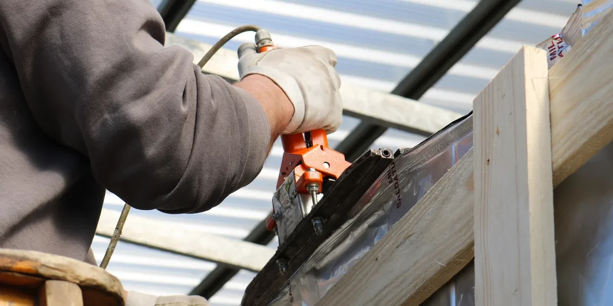
Most installations using cold room panels fail at the joint line. Right there. Modern insulated wall assemblies rely on factory-integrated tongue-and-groove joints with double-ridge EPDM gaskets that seal the panel union across the full width without needing extra field sealant.
When crews skip the layout checks or force a panel instead of letting the interlock seat properly, that action breaks the engineered air barrier immediately. At Rax Panel, we produce these assemblies daily, and I see exactly where field teams cut corners when they rush the install.
This guide walks through the actual sequence that keeps thermal bridges out and compression seals intact. We start with concrete floor flatness verification and vapor barrier placement before you ever lift a panel into position. You will also see how to set the first wall section, engage the interlocking cam locks, secure corner posts, and fit the door frame without disturbing the newly erected walls. Get these steps right and your crew avoids the condensation damage and energy waste that usually drive costly retrofits down the road.
Gather the Right Safety Gear and Tools First
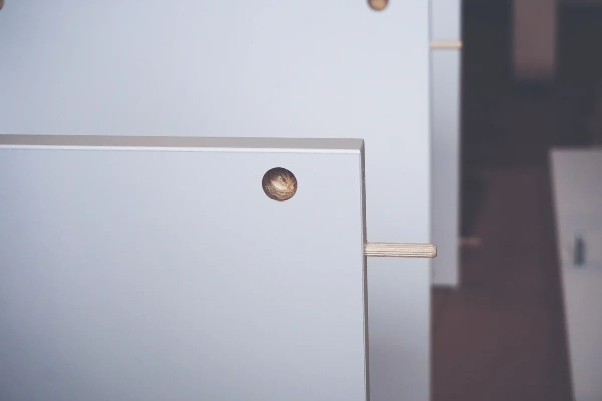
Before unloading the first shipment, having the correct Personal Protective Equipment (PPE) and precision installation tools is the single biggest predictor of a successful cold room build. Improper handling of composite panels—whether lightweight GRP or heavy-duty steel-faced PIR cores—can lead to immediate material damage or long-term thermal bridging failures.
The investment in high-quality cut-resistant gear and specific cam-lock fasteners safeguards both the installer and the integrity of the thermal envelope, ensuring that the cold room panel thickness for -20C storage performs as engineered without human-error compromises.
KEY TAKEAWAY: Safety prevents injury, but the right tools prevent thermal leakage. Prioritize cut-resistant PPE and dedicated cam-lock speed braces to ensure air-tight joints and maximize energy efficiency.
Essential PPE for Panel Handling
Handling industrial sandwich panels involves specific hazards ranging from sharp metal edges to skin-irritating glass fibers. Standard construction safety gear is often insufficient when dealing with the specialized facings found in modern composite panels. For instance, handling GRP (Glass Reinforced Plastic) or CFRT facings without proper respiratory and dermal protection can lead to immediate irritation and long-term health issues for your installation crew. We mandate a strict PPE protocol on our factory floors to ensure zero-compromise safety during material processing.
- Cut-Resistant Gloves (Level 5): Essential for handling steel, aluminum, or stainless steel facings to prevent lacerations from sheet metal edges.
- Safety Goggles or Face Shields: Critical during on-site cutting to protect eyes from flying metal shards and particulate matter.
- Dust Protection (N95 or P2 Masks): Mandatory when sawing into foam cores or sanding GRP/FRP facings to prevent inhalation of fiberglass dust or polyurethane particles.
- Steel-Toed Safety Boots: Non-negotiable for maneuvering heavy panels, which can weigh significantly depending on thickness and core density.
Cam-lock Key and Fastening Tools
The cam-lock system is the mechanical heart of a modular cold room, pulling panels together to create a continuous thermal seal. Using the wrong tool here is a common failure point; a standard Allen wrench often lacks the torque required or the speed needed for large-scale projects. In our experience working with international distributors, we have found that using improper drivers frequently strips the cam-lock mechanism, leading to loose joints that cannot be fixed without dismantling the wall.
- Hexagonal Cam-Lock Key (typically 5mm or 6mm): Ensure you have the specific size matching the panel manufacturer’s specifications. A magnetic tip helps prevent dropped keys inside panel joints.
- Speed Brace or Ratchet Handle: Attaching the hex key to a speed brace reduces installation time by up to 40% compared to a T-handle, providing the necessary force without stripping the screw head.
- Cordless Drill with Variable Torque: Required for driving self-tapping screws into wall tracks or steel sub-structures. We recommend a clutch setting adjustment to avoid over-compressing the foam core, which diminishes insulation value.
Sealant Applicators and Cutting Instruments
Precision cutting and sealing are the final barriers against condensation prevention cold room panel joints. Rough cuts leave gaps that sealant cannot fill, creating thermal bridges that compromise the room’s efficiency. Additionally, using low-grade applicators results in uneven bead application, which is the primary cause of air leakage in cold storage facilities. High-precision tools ensure that the PU foam sandwich panel thermal conductivity spec is maintained by preserving the integrity of the core material during modification.
- Circular Saw with Fine-Tooth Blade: Use a blade with at least 60-80 teeth (TCT) for metal facings to ensure clean, burr-free cuts. For fiberglass or GRP facings, use a blade specifically designed for composite materials to prevent fraying.
- Premium Caulking Gun: A high-thrust ratio (e.g., 18:1) gun is necessary to apply high-viscosity PU or silicone sealants consistently, ensuring the material penetrates deep into the tongue-and-groove joints.
- Square and Measuring Tape: Accurate measurement is crucial for custom sized insulated panels cold room dimensions. Even a 1mm deviation can accumulate across a large wall, causing misalignment in cam-locks.
Prepare Your Site and Level the Concrete Floor
A cold storage shell fails at the slab interface long before it fails elsewhere. The foundation must deliver uniform support, absolute moisture control, and geometric precision before a single insulated panel touches the ground.
Assessing Floor Flatness and Tolerances
Cold room assemblies rely on continuous base contact between composite wall panels and the slab. When the concrete surface undulates, the tongue-and-groove locking mechanisms cannot distribute pressure evenly. High spots act as unintended shims, forcing panels out of plumb and transferring point loads into the facings. Low spots leave voids that compromise the thermal break at the floor junction, allowing warm ambient air to infiltrate the sealed envelope.
Survey the entire footprint before scheduling panel delivery. Inspectors should check the slab along multiple axes rather than relying on isolated spot measurements, because localized waviness often masks a broader slope toward drains or loading docks. Any significant deviation must be mechanically ground down or rebuilt with a leveling compound, not compensated for with shims during installation. Forcing a panel onto an uneven surface creates hidden stress fractures and breaks the continuity of the vapor barrier at the base.
Installing Vapor Barriers on Concrete
Unconditioned concrete continuously breathes moisture from the ground up. In a refrigerated environment, that migrating water vapor hits cold panel cores and metal facings, triggering condensation behind the insulation. Once trapped between the slab and the composite sheet, moisture degrades foam density, reduces thermal resistance, and accelerates corrosion on steel or aluminum skins. The vapor barrier is not optional; it is the primary defense against long-term thermal decay.
Lay the membrane across the cleaned slab before marking the panel grid. Overlap all seams according to the membrane manufacturer’s specification and seal them with compatible adhesive tape. Pay strict attention to penetrations around drainage channels, evaporator condensate lines, and floor-mounted equipment pads. These transition zones are where most installation failures occur, because technicians often rush through sealing details instead of treating them as continuous waterproof interfaces.
- Surface contamination: Remove all dust, curing compounds, oil residues, and loose aggregate before adhering the membrane. Even thin films of dust break the chemical bond and create microscopic leak paths.
- Seam continuity: Run the barrier up slightly at wall transition points where the slab meets existing vertical structures, preventing lateral moisture migration behind the first row of panels.
- Protection during assembly: Sweep the finished membrane daily and repair punctures immediately. Heavy panel handling, rolling racks, and dropped fasteners routinely breach the layer if it is left unprotected.
Marking Wall Layout and Corner Positions
Precision starts with the chalk line. Transfer the project’s structural grid directly onto the slab, establishing exact wall centers, corner intersections, and door frame coordinates before any material leaves the packaging. Cold room panels are manufactured to tight dimensional tolerances, so the slab layout must match those dimensions precisely. If the layout line is off by even a small fraction, each successive cam-lock engagement compounds the error until the final panel cannot close the room without forcing the joint.
Corner positions require double verification. Corners absorb multidirectional loads from adjacent wall runs and serve as the anchor points for the entire interlocking sequence. Snap cross-lines at each intersection and measure diagonals to confirm squareness. A skewed corner forces panels into shear stress, which eventually loosens fasteners, gaps sealant beads, and allows cold air to bypass the gasket system.
- Reference datum: Anchor all layout measurements to a single fixed point on the slab or building column, never to temporary board edges that shift during installation.
- Clearance coordination: Mark evaporator mounting zones, condensate drain routes, and electrical chase locations on the slab before panel erection so the wall layout does not conflict with refrigeration infrastructure.
- Door rough openings: Dimension door frames on the ground first, then verify height and width against the panel stack sequence. Misplaced rough openings force field cutting of insulated panels, which destroys the factory seal and exposes raw foam to moisture.
| Site Preparation Parameter | Technical Standard | Engineering Significance |
|---|---|---|
| Concrete Flatness Tolerance | < 3mm deviation over 2-meter straightedge | Essential for achieving airtight seals at the base of wall panels; uneven surfaces compromise thermal efficiency and joint integrity. |
| Surface Moisture Control | Vapor barrier installed; Moisture content < 5% | Prevents ground humidity migration that can degrade foam core insulation (PU/PIR/PET) and cause flooring delamination or condensation. |
| Compressive Load Capacity | Minimum 20 MPa (3000 psi) strength | Supports the cumulative weight of fully loaded racking systems and refrigeration equipment without foundation settlement or cracking. |
| Surface Finish Quality | Steel-trowel finish, free of sharp protrusions | Critical for protecting the bottom facings of composite sheets (GRP, Stainless Steel, or Aluminum) from abrasion and puncture during installation. |
| Levelness & Squareness | ±5mm elevation variance; 90° corner accuracy | Ensures precise vertical alignment of modular sandwich panels and minimizes gaps during the tongue-and-groove assembly process. |

Set the First Panels and Check Them Before Locking
The first panel sets the geometric baseline for the entire wall assembly. Align it to the layout mark, verify plumb within ±1mm per meter, and reject any unit with visible facing damage or missing thermal certificates before the locking mechanism engages.
Setting the initial cold room panels correctly eliminates compounding alignment errors for every subsequent slab. During freight transit, sandwich panels absorb vibration and contact stress, which frequently causes micro-scratches on metal facings, compressed corner edges, or weakened vapor barrier seals. Once the panels land on the prepared floor track, the installation crew must treat the first unit as the master reference.
Position it precisely on the marked layout line, confirm the gap tolerance matches the engineering drawing, and hold a calibrated spirit level or laser plummet against the leading edge. If the panel deviates beyond ±1mm per meter of height, adjust the base shims or reseat the track interface before attempting to lock the next panel. Never force an out-of-plumb slab into the cam-lock groove; mechanical engagement will amplify the misalignment across the entire wall run.
Damage Inspection and Certification Cross-Check
Procurement risk spikes when delivered materials lack verifiable thermal ratings or carry undocumented substitutions. A panel labeled for -20°C dry storage must match the contracted polyurethane or PIR core specification, with thermal conductivity values documented on the batch certificate.
General contractors should run a side-by-side verification against the purchase order before any panel is lifted into position. Missing UL, CE, or equivalent insulation test reports do not merely delay paperwork; they invalidate energy-efficiency warranties and expose the facility operator to condensation failure at joint seams.
- Facings: Scan both skin surfaces under raking light for scratches, dents, or coating blistering that could breach corrosion protection.
- Edge Cores: Inspect cut ends for voids, uneven foam expansion, or delamination between the core and facing sheet.
- Certification Docs: Match the mill test report to the ordered core material, thickness tolerance, and declared thermal conductivity rating.
- Vapor Barrier Integrity: Verify that the internal moisture seal remains continuous along the locked edges and corner interfaces.
Thickness Tolerance and Plumb Verification Protocol
Material quality standardization is the primary defense against inconsistent cooling loads. Commercial cold room panels are typically engineered to a nominal thickness tolerance of ±1mm, but field variations outside this band create thermal bridges at the joints.
When the first panel sits against the starter track, measure the actual face-to-face depth at three points: top, middle, and bottom. Any reading that falls outside the specified tolerance indicates a core compression issue or facing warp that will prevent a hermetic cam-lock seal.
Vertical alignment must be confirmed before any lateral locking hardware engages. Use a laser level or precision plumb bob anchored to the finished floor datum. Hold the instrument against the leading edge, lock the panel in place with temporary bracing, and re-check the measurement after shifting weight from the handling rig.
Only when the panel reads true vertically and horizontally should the interlocking joint be fully engaged. Forcing the mechanism on an unverified slab shifts load transfer away from the track, concentrates stress at the foam core, and guarantees seam leakage once the refrigeration cycle begins cycling humidity.
Never use the adjacent locked panel as your plumb reference. Every new slab must be checked independently against the floor datum, because cumulative tolerance drift will compound across a full wall run and break the thermal seal at the final corner post.
Engage the Interlocking Joints for a Continuous Seal
Engaging interlocking joints correctly is non-negotiable for maintaining a continuous vapor barrier in sub-zero cold storage. A single misaligned groove or interrupted sealant bead creates a thermal bridge that invites condensation, equipment corrosion, and compromised product integrity.
The Mechanical Lock as a Vapor Barrier Anchor
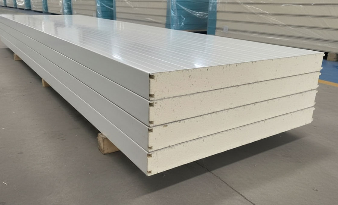
Tongue-and-groove and Z-lock profiles are engineered to do more than align panels; they physically trap the insulation core and anchor the vapor barrier across the entire wall run. When the male edge seats fully into the female channel, the composite face sheets create a continuous plane that blocks humid air migration.
At -20°C storage conditions, even a 2mm gap between mating surfaces disrupts the thermal envelope and accelerates frost buildup along the seam. Properly seated joints distribute mechanical stress evenly across the panel edges rather than concentrating load at a single contact point.
Sealant Placement and Chemistry Compatibility
Generic exterior silicones often fail inside insulated panel cavities because they lack the flexibility to absorb structural movement or bond reliably to foam cores. The correct approach requires running a continuous bead of cold-room-grade mastic or PU foam inside the female groove before engaging the male edge.
Butyl tape acts as a secondary backup at the perimeter, while spot-sealing voids creates false security. Incompatible joint geometries paired with untested adhesives force costly retrofits once condensation appears behind the cladding.
- Joint Profile Match: Verify tongue height and groove depth against the panel thickness before ordering accessories.
- Sealant Application: Apply adhesive in a continuous 360-degree bead within the groove, never at discrete intervals.
- Thermal Break Integrity: Ensure facings overlap sufficiently to prevent conductive bridging through exposed metal or core material.
Detecting Misalignment Before Full Engagement
Forcing panels together when the mounting surface or previous course is out of tolerance cracks the joint seal and distorts the locking mechanism. Contractors should dry-fit each segment, confirm vertical plumb, and check that the tongue enters the groove without lateral resistance.
This prevents micro-fractures in the insulation core that become permanent leak paths over repeated thermal cycling. Uniform compression across the full seam length is the only reliable indicator that the vapor barrier remains intact.
Improper joint compression does not just cause air leaks; it creates localized cold spots where condensation forms on interior metal surfaces. Over time, trapped moisture corrodes fasteners, degrades foam adhesion, and introduces food safety hazards in regulated storage environments.
Always inspect the female groove for debris, old adhesive residue, or factory mold release before sliding the next panel into place. Contamination here is the fastest reason for a failed continuous seal.
📋 Joint Engagement Checklist
- Step 1: Confirm panel orientation and verify the tongue-and-groove profile matches the design specification.
- Step 2: Apply cold-room mastic or PU foam continuously inside the female groove prior to assembly.
- Step 3: Align the male edge and press downward evenly until the faces sit flush with no visible step.
- Step 4: Wipe excess sealant immediately and inspect the seam for uniform compression across the full length.
Secure the Corner Posts for a Sturdy Build
Corner posts are the load-bearing spine of a cold room assembly. Securing them correctly prevents panel racking, maintains interlock seal integrity, and eliminates thermal bridges at high-stress intersections.
When constructing insulated wall systems for temperature-controlled storage, the corner post absorbs the majority of shear forces generated by door operation, racking loads, and panel thermal expansion. A deviation of just 2 mm out of plumb at the base can compound across a standard 6-meter wall run, preventing interlocking joints from fully engaging. This misalignment creates uncontrolled air leakage paths and compromises the entire thermal envelope.
Structural Anchoring and Floor Interface
The foundation of a rigid corner lies in the connection between the post channel and the prepared slab. Use corrosion-resistant anchor bolts, typically M10 or M12 stainless steel, spaced at maximum 600 mm vertical intervals. For metal-faced sandwich panels, isolate the bolt head with neoprene or EPDM washers to prevent galvanic corrosion between dissimilar metals.
- Anchor pull-out resistance must scale with the thermal severity of the storage zone to accommodate contraction and cyclic stress. Specify a minimum pull-out resistance of 4 kN per anchor for standard cooler applications; increase to 6 kN for freezer environments operating at -20°C or below, where thermal contraction, vibration, and cyclic loading inherent to sub-zero environments necessitate the higher rating.
- Floor Track Integration: If using a continuous top and bottom track system, secure the corner post flange directly through the track into the structural subfloor. Ensure the track is leveled within ±1 mm over the full room perimeter before final fastening.
- Vapor Barrier Penetration: Where a polyethylene vapor barrier is installed on the concrete slab, seal all anchor penetrations with closed-cell polyurethane foam or butyl tape to maintain the moisture control layer without adding structural stiffness.
Panel-to-Post Connection and Alignment
Once the vertical post is plumbed and temporarily braced, insert the first wall panel’s interlocking edge into the post channel. Do not rely solely on the cam-lock mechanism to hold the post position during construction. Drill through-bolt holes through the panel facing into the post web, or use side-fastening clips designed for the specific panel thickness.
For sandwich panels with rigid foam cores such as polyurethane (PU) or polyisocyanurate (PIR), control fastener torque carefully. Over-tightening can crush the core material around the bolt, reducing local compressive strength and creating a localized thermal bridge. Target a seated torque that pulls the facing flush against the post without deforming the panel surface.
Reinforcement for Demanding Environments
In applications requiring high impact resistance or extreme thermal stability, standard extruded aluminum or steel posts may require supplemental bracing. Internal fiberglass reinforced thermoplastic (CFRT) corner profiles offer superior resilience and lighter weight compared to traditional metal channels. These composite corners distribute point loads more evenly across the panel intersection.
- Thermal Contraction Mitigation: At temperatures below -15°C, metal posts contract at a different coefficient than polymer foam cores. Use flexible sealant at the post-to-foundation interface to accommodate movement without cracking the insulation layer.
- High-Span Reinforcement: For wall heights exceeding 3 meters, add diagonal bracing inside the corner post cavity or install external stiffener plates rated for the specific panel face gauge to prevent buckling under lateral loads.
- Fire-Rated Joints: Where building codes require fire resistance at penetrations, use intumescent sealants around corner post fasteners. Ensure the chosen foam core, whether PU or PIR, meets the required Euroclass or ASTM fire rating for the installation zone.
<!– wp:html –>
<!– /wp:html –>
Fit the Door Frame Without Disturbing the Walls
To fit a door frame without disturbing structural integrity, the frame thickness must match the wall panel perfectly, and installation must rely on chemical adhesion rather than mechanical impact.
Dimensional Alignment and Thermal Compatibility
The fundamental rule of installing a door frame in a composite sandwich panel system is zero-tolerance dimensional matching. If the wall utilizes 100mm thick PU (Polyurethane) or PIR (Polyisocyanurate) foam core panels, the door frame must be engineered to the exact 100mm depth. A mismatch here forces the installer to either compress the wall panels—risking core damage—or leave a gap that destroys thermal efficiency.
the material composition of the frame must account for thermal bridging. Standard steel or aluminum frames without a thermal break will conduct heat rapidly, causing condensation and ice buildup at the threshold—a critical failure point in cold storage. High-performance frames typically integrate a thermal barrier strip, often polyamide or a similar low-conductivity material, to maintain the insulation value of the surrounding wall panels.
Non-Invasive Installation Techniques
- Sealant Application: Apply a continuous bead of high-grade polyurethane or silicone sealant to the mounting flange of the door frame before placement. This ensures an immediate airtight and watertight seal upon contact.
- Gentle Positioning: Lift the frame into the rough opening and align it plumb and level. The frame should sit snugly without requiring force. If it is too tight, trim the panel facing, never the core structure.
- Self-Tapping Fasteners: Use self-drilling screws with neoprene washers. These create a secure mechanical anchor without the need for pre-drilling that might generate excessive vibration or dust, preserving the integrity of the panel joints.
Gasketing and Operational Integrity
Once the frame is securely mounted, the interface between the door leaf and the frame is the final critical line of defense. Disturbing the wall during installation often leads to misalignment, causing the door to drag or fail to seal correctly.
Cold room doors, whether hinged or sliding, rely on heavy-duty heated gaskets to prevent freeze-down. Rubber or PVC magnetic gaskets must be inspected to ensure they compress uniformly against the frame surface when the door is latched. Any distortion in the frame caused by rough installation will result in a gap, allowing infiltration of warm air and moisture, which inevitably leads to ice formation at the door base.
Seal Every Joint to Prevent Air Leaks
Joint sealing determines cold room envelope integrity. Warm air crossing unsealed seams destroys insulation performance faster than any core material failure.
Compatible Sealant Chemistry Matters More Than Application Speed
Generic silicone or standard polyurethane caulks often degrade quickly in refrigerated environments. Many lose elasticity during repeated freeze-thaw cycles, crack along the joint line, or chemically interact with foam cores such as PU, PIR, XPS, PET, or PVC. Cold-storage-grade sealants must stay flexible at sub-zero temperatures while acting as a continuous low-permeability vapour barrier across every penetration, including electrical conduits and structural supports.
Using incompatible sealants against mismatched tongue-and-groove geometries guarantees early retrofit work. The mechanical interlock handles panel alignment and initial air resistance, but the sealed groove is what actually stops moisture migration. If the sealant does not fully bridge the groove depth and match the panel thickness, thermal bridging forms along the joint line.
- Sealant Flexibility: Must retain elasticity across the full operating temperature range without cracking or shrinking at joint edges.
- Vapour Barrier Continuity: Every joint, fastener penetration, and core cut must remain vapor-tight to prevent moisture absorption into the insulation.
- Core Compatibility: Sealant chemistry must be verified against PU, PIR, XPS, PET, PVC, and honeycomb cores to avoid adhesive breakdown or chemical staining.
- Joint Geometry Match: Tongue-and-groove depth and panel thickness dictate sealant volume requirements; undersized beads leave unsealed pathways.
Hidden Energy Costs From Poor Joint Execution
Thermal efficiency collapses the moment air leakage bypasses the insulation layer. A 100 mm PU or PIR sandwich panel can reliably maintain -5 °C storage loads under proper installation conditions, but the same assembly frequently fails to hold -25 °C when joint seals are incomplete. Compressors then run continuously to compensate for heat infiltration, driving kilowatt-hour consumption well above design projections.
Ignoring sealant compatibility with cold-room panel cores turns a quick fix into a long-term energy liability. Exterior icing at joints is not cosmetic; it confirms active thermal bridging and progressive envelope failure.
Condensation inside or along panel joints accelerates metal corrosion on facings, degrades thermal resistance as foam absorbs moisture, and introduces hygiene risks in food-grade cold storage. Proper joint sealing is not optional detail work—it is the defining factor between a cold room that meets its design temperature and one that silently consumes excess power while compromising stored inventory.
Run a Final Check on Structure and Seals
Conducting a rigorous final inspection of the structure and seals is the last line of defense against thermal bridging, air infiltration, and long-term energy inefficiency in cold storage environments.
Inspecting Cam-lock Engagement and Tightness
The cam-lock mechanism serves as the primary tensile connection between sandwich panels, pulling tongue-and-groove joints together to create a unified wall structure. While visual inspection might suggest the panels are flush, the mechanical connection must be verified to ensure structural rigidity and proper gasket compression. An unengaged or partially rotated cam-lock can leave a visible gap that compromises the room’s airtightness, leading to thermal bridging where heat penetrates the insulation layer.
Inspectors should systematically check every cam-lock access point. The locking lever must be fully rotated to its closed position, typically engaging a 90 or 180-degree turn depending on the manufacturer’s specification. Resistance during the final turn indicates that the panels are being drawn together with the necessary force. If a lock spins freely without resistance (“ghost tightening”), the internal mechanism may be stripped or misaligned, requiring immediate panel adjustment or replacement to prevent future joint failure.
📋 Actionable Steps
- Step 1: Visually confirm that all cam-lock levers are in the fully closed, horizontal position.
- Step 2: Perform a tactile check by attempting to wiggle adjacent panels; there should be zero movement at the joint.
- Step 3: Inspect the injection hole to ensure it is properly sealed with the provided plastic cap to maintain vapor barrier continuity.
Verifying Joint Sealant Continuity
Sealant application is the critical barrier against moisture ingress and air leakage. Even with perfectly engaged cam-locks, the integrity of the seal relies on a continuous, uninterrupted bead of sealant applied within the joint groove. Breaks or voids in the sealant line create direct pathways for humid air to enter the assembly, where it can condense within the wall cavity and degrade the insulation core or cause corrosion on metal facings.
Verification involves examining the joints for “squeeze-out”—a visible indication that the panels have compressed the sealant sufficiently to fill the gap. The sealant should be consistent along the entire vertical and horizontal runs. Special attention must be paid to corner intersections and penetration points where complex geometries often lead to inconsistent application. Any gaps or dry spots identified must be addressed immediately with a compatible sealant to restore the vapor barrier’s integrity before the room is put into service.
Testing Door Gasket Compression
Doors are the most dynamic and vulnerable part of a cold storage enclosure, subjected to frequent cycling and physical stress. The door gasket acts as the flexible seal that accommodates this movement while maintaining the thermal envelope. Without uniform compression, the door frame becomes a significant source of energy loss. Over time, gaskets can suffer from compression set, where the material permanently deforms and loses its ability to spring back, resulting in gaps even when the door is latched.
Testing compression requires checking the contact surface between the gasket and the door frame or strike plate. The gasket must make full contact around the entire perimeter—top, sides, and bottom. A common field test involves inserting a thin piece of paper or a specific feeler gauge between the gasket and the frame, closing the door, and checking for drag.
If the paper slides out easily or there is no resistance, the seal is insufficient. Adjustments to the hinges or latches may be required to realign the door and restore even pressure distribution across the sealing surface.
Do not rely solely on the door latch mechanism to pull a warped door into seal. If the door frame or panel is structurally out of square due to settling or installation errors, the gasket will not compress evenly, leading to rapid ice formation at the leakage points.
| Inspection Point | Critical Parameter | Target Standard | Common Risk | Performance Impact |
|---|---|---|---|---|
| Joint Sealing Integrity | Gasket Compression & Adhesion | Uniform compression on tongue-and-groove joints with no visible gaps; sealant fully cured. | Thermal bridging and air leakage due to poor compression. | Increased energy consumption and potential ice buildup. |
| Core Material Continuity | Foam Density & Uniformity | Consistent density throughout the panel core without voids or shrinkage. | Internal voids or settling causing uneven thermal insulation. | Reduced R-value leading to temperature fluctuations. |
| Facing Surface Quality | Adhesion Strength & Flatness | Smooth, flat surface with strong adhesion to core; no delamination. | Delamination or surface damage allowing moisture ingress. | Corrosion risk and compromised hygiene standards. |
| Structural Connections | Fastener Torque & Alignment | Secure cam-lock or bolted connections; panels plumb and level. | Misaligned or loose fasteners creating gaps. | Structural instability and long-term air infiltration. |
| Vapor Barrier Continuity | Barrier Integrity & Continuity | Continuous vapor barrier layer intact across all seams and penetrations. | Punctures or gaps in the vapor barrier layer. | Condensation within wall cavities causing mold or rot. |
Key Takeaways
Installing cold rooms is about tolerance, not just torque. If your concrete floor isn’t flat, those cam-locks won’t align correctly. That gap kills your thermal efficiency faster than a cheap compressor ever will. You must check the vapor barrier continuity and seal every joint before moving to the next panel. Rushing the corner posts guarantees condensation issues down the line. Take your time on the layout marks and door frame placement.
If you hit a snag with thermal expansion calculations or joint spacing, get our engineers on the line. Rax Panel deals with these tolerances daily, and we can help validate your layout specs before you unload the first truck. Don’t guess on the sealant application for a -20C environment. Let us review your design details to ensure the envelope holds.
Frequently Asked Questions
This factor has a direct bearing on project performance and long-term cost. Addressing it with specific data rather than general assumptions leads to better outcomes.
What are cold room panels made of?
Cold room panels typically consist of two structural facings bonded to a rigid polyurethane or polyisocyanurate foam core. Common facing materials include galvanized steel, stainless steel, aluminum, or glass-reinforced thermoplastic composites. The core provides the primary thermal resistance, while the facings deliver impact strength and surface hygiene. At , engineers select facing and core combinations based on the required temperature range and load conditions.
How thick should cold room panels be?
Panel thickness depends directly on the target operating temperature and local energy code requirements. Specifiers evaluating cold room panel thickness for -20C storage should validate the PU foam sandwich panel thermal conductivity spec against independent laboratory testing. Thicker assemblies improve the overall R-value per inch and reduce thermal bridging across the envelope. Always confirm that certified test reports match the actual batch being delivered to the site.
PU vs PIR cold room panels?
Polyurethane and polyisocyanurate foams both deliver excellent thermal insulation, but their molecular cross-linking differs slightly. PIR panels generally offer higher fire resistance and a marginally better thermal conductivity spec at equivalent thicknesses. The PIR vs PU cold room insulation panels comparison ultimately hinges on project-specific fire codes, budget constraints, and regional availability. Neither core is universally superior; the correct choice depends on the facility’s operational priorities.
Are cold room panels easy to install?
Modern sandwich panels use interlocking tongue-and-groove or cam-lock systems designed for rapid field assembly. Proper installation requires a level substrate, precise panel sequencing, and technicians familiar with an industrial cold storage wall panel installation guide. Incorrect alignment or rushed sealing can compromise the vapor barrier and increase long-term refrigeration loads. Following manufacturer joint protocols ensures consistent thermal performance across the entire enclosure.
How do you prevent condensation at joints?
Condensation forms when warm, moist air penetrates unsealed panel interfaces and contacts cold surfaces. Installing continuous closed-cell gaskets, applying compatible polyurethane sealants, and securing interlocking edges eliminate air infiltration paths. A rigorous condensation prevention cold room panel joints protocol during commissioning protects both the structure and stored inventory. Thermal bridging at metal fasteners should be minimized using insulated brackets or breakaway connectors.