
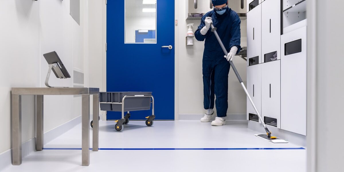
A clean room is a controlled environment where particle concentration, temperature, humidity, and pressure sit inside defined, measurable limits. ISO 14644 sets those limits by class, and even ISO 8 — the least stringent grade most facilities run — caps 0.5-micron particles at 3.52 million per cubic meter. Ambient office air carries roughly ten times that count. Miss the class in either direction and you fail validation, or you pay for over-filtered air every hour the room runs.
Fifteen years around these projects has taught me one blunt lesson: the classification table gets all the agonizing, and the wall panels are what trigger the audit findings. Your HVAC can be flawless. One shedding panel core or an undocumented surface finish still fails you. At RaxPanel, we build that part of the room — the wall and ceiling envelope — and we treat surface test reports and thermal conductivity data as standard deliverables, because your GMP file and your condensation calculations both depend on them.
The sections ahead cover the calls that decide first-pass validation: how ISO 14644 classes and GMP grades A–D map to actual particle limits, which air change rates and pressure cascades each grade demands, and how to judge wall, floor, and door systems against a written spec. Make those calls before the RFQ goes out. It costs far less than re-validating a room you built wrong.
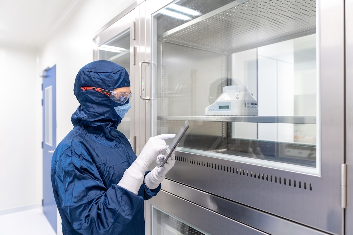
What Is a Clean Room?
A clean room is an engineered enclosure where airborne particle concentration is actively controlled and verified against a defined standard — most commonly ISO 14644-1. It is defined by its air, its pressure, and its sealed envelope, not by how often the surfaces are wiped down.
What Defines a Clean Room Environment
Engineered from the ground up, a clean room is a controlled environment where airborne contamination is managed through design—not through cleaning frequency. The defining metric is the maximum allowable particle count per cubic meter at specified size thresholds, which sets the numerical limit that the space must maintain.
Three physical parameters define a clean room, and all three must work together: airborne particle concentration measured in particles per cubic meter, positive or negative pressure differentials measured in pascals that direct airflow from cleaner to dirtier zones, and controlled temperature and humidity ranges that protect both the product and the process. Remove any one of these, and the room ceases to be a clean room — it becomes just a clean space.
The classification system matters because it tells you exactly what air quality to design for. ISO 14644-1 defines classes from ISO 1 (the cleanest, used in semiconductor lithography) through ISO 9 (the loosest, roughly equivalent to a standard office environment). A pharmaceutical manufacturer targeting EU GMP Grade A operates at a particle density that falls between ISO 3 and ISO 4. A medical device assembly area might sit comfortably at ISO 7 or 8. Your classification choice drives every downstream decision — HVAC sizing, panel selection, door configuration, and ultimately your energy bill.
Our engineering team works with facility planners who are designing their first clean room, and the most common mistake we see is over-classification. A client specifies ISO 5 because it sounds impressive, only to discover three years later that they are spending triple the necessary HVAC operating cost for a process that would have passed at ISO 7. ISO 14644-1 gives you the limits; your process risk assessment tells you which limit actually matters.
Core Components: Air Handling, Walls, and Flooring
A clean room is a system of interdependent components. The air handling unit — the AHU — conditions and delivers filtered air. The walls and ceiling form the sealed envelope. The floor provides a continuous, cleanable base. Each component must be specified to work with the others, because a failure in any single element compromises the entire classification.
The air handling system is the lungs of the clean room. It draws in outdoor air, conditions it to the required temperature and humidity, pushes it through pre-filters and then through HEPA or ULPA filters, and distributes it through diffusers or laminar flow fixtures. The rate at which it replaces the room air — measured in air changes per hour — is the primary lever for controlling particle concentration. ISO 14644-1 does not prescribe a specific ACH number; it defines particle limits. The ACH requirement is a design consequence derived from your particle target, room volume, occupancy, and internal contamination load.
The wall and ceiling envelope is where RaxPanel operates. While HEPA filtration and HVAC handle the air, our smooth, non-particulating GRP/FRP and stainless steel sandwich panels form the sealed, wipeable wall and ceiling skin that keeps those systems from being undermined by shedding, porous, or hard-to-sanitize surfaces. Gelcoat-finished GRP panels and stainless steel facings deliver particle-free, moisture-proof, and chemically resistant surfaces that stand up to repeated disinfection cycles without degrading. Our production engineers see certification failures at panel joints first — not on the flat face of the panel, but at the unsealed transitions where dust accumulates and cleaning chemicals cannot reach.
The floor must be seamless, chemically resistant, and capable of withstanding routine wet cleaning and periodic disinfection with agents such as isopropyl alcohol, hydrogen peroxide vapor, and quaternary ammonium compounds. Epoxy resin coatings and polyurethane mortars remain the traditional choice, but modern clean rooms increasingly specify seamless thermoplastic polyurethane or methyl methacrylate flooring systems that cure into a jointless surface with no ridges or seams to harbor contaminants.
Every penetration through the envelope — for electrical conduits, process piping, or ductwork — is a potential contamination pathway. Our team reviews penetration details during the design phase because an unsealed 12-millimeter conduit hole can undermine an otherwise well-designed ISO 7 environment. Panel joints, wall-to-floor coving, and penetrations are where clean room validation succeeds or fails, and this is exactly where modular sandwich panel design quality becomes decisive.
How HEPA Filtration Controls Airborne Contamination
HEPA filters — High Efficiency Particulate Air filters — are the primary mechanical barrier between contaminated outdoor air and the clean room environment. A true HEPA filter, as defined by ISO 29461-3 (formerly EN 1822), captures at least 99.97% of airborne particles at the most penetrating particle size of 0.3 micrometers. Particles larger or smaller than 0.3 micrometers are actually captured at even higher efficiencies due to different collection mechanisms — larger particles by impaction and interception, smaller particles by diffusion.
ULPA filters — Ultra Low Particulate Air filters — are used when the target classification is ISO 4 or cleaner. They capture 99.999% of particles at 0.12 to 0.15 micrometers. In practice, ULPA is standard in semiconductor fabrication and some Grade A pharmaceutical filling areas, while HEPA dominates ISO 5 through ISO 8 environments across pharmaceutical, medical device, and general industrial clean rooms.
The relationship between filtration and air changes per hour is the core equation of clean room design. More air changes mean more filter passes per hour, which means lower steady-state particle concentration. But more air changes also mean higher fan energy, larger ductwork, more heating and cooling load, and greater operational cost. This is why ACH is never chosen arbitrarily — it is calculated from your particle budget, your occupancy rate, your process contamination sources, and your acceptable operating cost.
For an ISO 7 clean room, the practical ACH range typically falls between 60 and 90 air changes per hour, though the exact number depends on room volume, occupancy, and internal heat load. ISO 8 environments commonly operate between 20 and 40 ACH. These are design practices, not ISO-mandated numbers — ISO 14644-1 defines particle counts, not airflow rates. The confusion in the market around ISO 7 ACH requirements exists precisely because different consultants and vendors quote different ranges based on their default design assumptions rather than project-specific calculations.
HEPA filter integrity must be verified after installation. DOP or PAO testing — using a mono-disperse aerosol challenge upstream of the filter — confirms that the filter media and its seal at the frame are intact. A properly installed HEPA filter with an intact gasket seal should show zero downstream challenge aerosol. Any detectable reading indicates a leak that must be addressed before the room can be classified. This testing is non-negotiable and is required by ISO 14644-2 for initial certification and by ISO 14644-3 for periodic requalification.
Every unsealed panel penetration forces the AHU to compensate by moving more air to maintain pressure differentials. The envelope air-tightness of your wall and ceiling panels directly sets the facility’s decade-long energy bill. This is the connection that most first-time clean room planners miss: the panel joint quality you specify today determines your HVAC operating cost for the next 15 to 20 years.
Common Misconceptions: What Clean Rooms Are Not
The clean room industry is full of shortcuts disguised as best practices. Understanding what a clean room is not is just as important as understanding what it is, because each misconception carries real compliance and cost risk.
- A clean room is not a sterile room. Cleanliness and sterility are different concepts. A clean room controls particulate and microbial contamination to a defined level. Sterility means the complete absence of all living microorganisms. ISO 14644-1 addresses particles. EU GMP Annex 1 and USP 797 address microbial load and sterility assurance. You can have an ISO 5 clean room that is not sterile, and you can sterilize an item in a non-clean environment. The terms are not interchangeable, and confusing them leads to specification errors that show up during audits.
- A clean room is not defined by surface cleaning frequency. Wiping down walls daily does not make a room a clean room. A conventional office that is mopped and dusted every day still fails ISO 8 particle counts. Clean rooms are defined by engineered air filtration, controlled pressure cascades, and sealed construction — not by janitorial schedules. The surfaces must be cleanable, yes, but the cleanliness of the air is what defines the classification.
- A clean room is not an airtight box. Clean rooms are pressurized, not sealed. Air must flow through the space — entering through HEPA-filtered supply diffusers, sweeping across the work area, and exiting through return grilles — to carry contaminants away. The pressure differential is maintained by supplying slightly more air than is exhausted, creating a gentle outward flow at doors and penetrations. If a clean room were truly airtight, the pressurization would build to structural limits and the HVAC system would struggle against static pressure. The design intent is controlled airflow, not air exclusion.
- A higher ISO class is not always better. Classifying one ISO class cleaner than your process requires costs roughly three times the air-change energy for zero compliance benefit. An ISO 6 room serving an ISO 7 process does not improve product quality — it increases your energy bill, your filter replacement frequency, and your validation complexity. Regulators hold you to the classification you declare. If you label a room Grade D under EU GMP, they will test it to Grade D requirements, and over-classifying does not earn you credit. Specify the minimum class that your process risk assessment justifies.
- A modular clean room is not a temporary or lower-quality solution. This misconception is particularly damaging because it affects procurement decisions. Modern modular clean room panels — such as gelcoat-finished GRP sandwich panels and stainless steel-faced composite panels — are engineered for the same certification standards as cast-in-place concrete clean rooms. The joint design, surface smoothness, and chemical resistance of a properly specified modular panel system meet GMP and ISO requirements when the panel joints are correctly coved and sealed. The advantage of modular construction is speed of installation, traceability of components, and the ability to reconfigure the space as process needs change — without compromising classification integrity.
The most common certification failure we encounter is not a panel surface defect — it is an unsealed joint or a coving discontinuity between the wall panel and the floor. Auditors and particle counters do not care about the face material if the transition detail allows dust accumulation. Always specify continuous coved joints and gasketed panel interfaces from the design stage, not as an afterthought during installation.
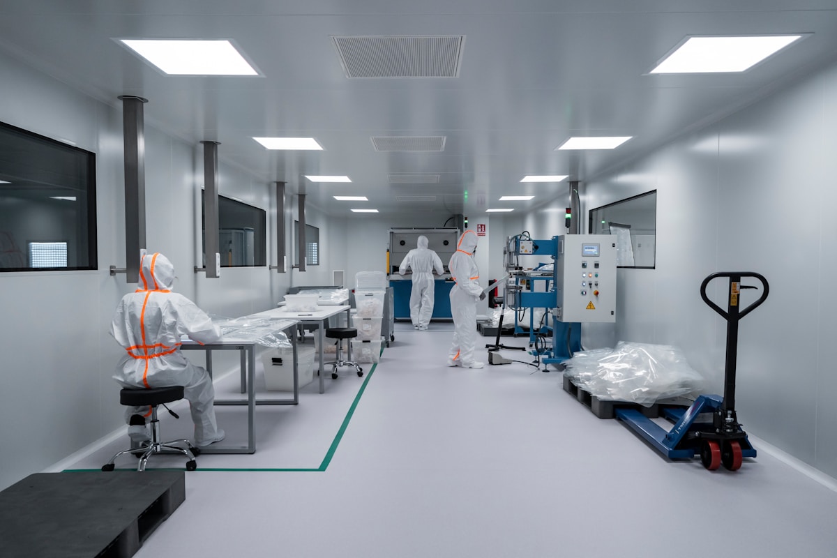
How Clean Rooms Are Classified
Clean room classification is governed by ISO 14644, which sets particle limits, and by GMP frameworks that define microbial and particulate standards for pharmaceutical manufacturing. Understanding both systems is essential for selecting the right environment for your process.
ISO 14644 Cleanliness Classes Explained for Beginners
The ISO 14644 standard, published by the International Organization for Standardization, provides a globally recognized framework for classifying air cleanliness in controlled environments. The system divides clean rooms into nine classes, numbered ISO 1 through ISO 9, with ISO 1 representing the cleanest conditions and ISO 9 approaching typical ambient indoor air quality.
Each ISO class defines a maximum allowable concentration of airborne particles of specific sizes per cubic meter of air. The classification is not arbitrary — it is derived from a logarithmic formula that links particle count to room cleanliness等级. In practice, this means that moving from ISO 8 to ISO 7 requires roughly ten times fewer particles, and each subsequent class down represents another order of magnitude reduction.
For beginners, the simplest way to think about ISO classification is to treat it like a tiered ranking system. ISO 1 through ISO 3 are reserved for the most demanding applications, such as nanofabrication and advanced semiconductor lithography. ISO 4 and ISO 5 are commonly found in pharmaceutical aseptic processing and precision electronics assembly. ISO 6 and ISO 7 serve industries like medical device manufacturing and optical component production. ISO 8 and ISO 9 are the most accessible and are used for general manufacturing support areas and packaging zones.
Notably that ISO 14644 does not specify how to achieve a given classification. That responsibility falls to the facility designer, who must select appropriate HVAC capacity, filtration type, airflow pattern, and surface materials to meet the target class through validated engineering controls.
How Particle Counts Determine Each Class
At the heart of every ISO classification is a particle count limit. These limits are measured using calibrated optical particle counters that sample air at defined flow rates and record the number of particles detected at four standard size thresholds: 0.1 micrometers, 0.2 micrometers, 0.3 micrometers, and 0.5 micrometers. Some classifications also include a 5.0 micrometer threshold for larger particulate matter.
The reason multiple particle sizes are tracked is that contamination risk varies by application. In semiconductor manufacturing, even a single particle larger than 0.5 micrometers can short a microcircuit trace. In pharmaceutical aseptic processing, particles in the 0.5 to 5.0 micrometer range may carry viable microorganisms and pose a sterility risk. By monitoring all size bands, operators can assess which type of contamination is most likely to threaten their process.
When measuring particle counts, the standard requires testing under two conditions: at rest and in operation. At-rest testing is performed with the clean room fully furnished and HVAC systems running, but with no personnel present. In-operation testing is conducted while the facility is actively running with operators present. The in-operation count is always higher than at-rest, and the difference between the two values is a strong indicator of how well the room design controls human-generated contamination.
A common misconception among newcomers is that lower particle counts automatically mean a better clean room. This is not necessarily true. A room may meet its ISO classification on paper but still fail in practice if surface contamination, personnel practices, or pressure cascade design are inadequate. Particle count is only one dimension of clean room performance. Surface cleanliness, microbial load, and environmental stability are equally critical and must be evaluated alongside airborne metrics.
Understanding GMP Grades A Through D
While ISO 14644 governs particle cleanliness globally, the pharmaceutical and biotechnology industries follow an additional framework known as Good Manufacturing Practice, or GMP. GMP classification is defined by regional health authorities — primarily the European Medicines Agency (EMA) and the U.S. Food and Drug Administration (FDA) — and uses a four-grade system: Grade A, Grade B, Grade C, and Grade D.
Grade A represents the highest level of protection and is required for operations where product exposure is greatest, such as aseptic filling, stopper bowl handling, and open-vessel manipulations. In practice, Grade A is typically provided by a laminar airflow work station or a unidirectional airflow canopy that sweeps contaminated air away from the product at a controlled velocity. The air quality under Grade A conditions is roughly equivalent to ISO 5 at 0.5 micrometers, but GMP Grade A also imposes strict microbial limits that ISO classification alone does not address.
Grade B serves as the background environment for Grade A areas. It is the cleanest support zone and must maintain both particulate and microbial control. Operators entering a Grade B area require more stringent gowning than in lower grades, and the HVAC system must sustain positive pressure relative to adjacent zones to prevent cross-contamination.
Grade C and Grade D are progressively less stringent but still require controlled environments. Grade C is commonly used for preparatory steps such as solution mixing and filling of non-sterile products that will undergo terminal sterilization. Grade D is the minimum requirement for areas producing non-sterile but hygienically controlled products, and it serves as the outermost controlled zone in a pharmaceutical facility.
The relationship between ISO classes and GMP grades is not one-to-one. A room classified as ISO 7 at rest may serve as a Grade C environment, while an ISO 8 room at rest may correspond to Grade D. However, GMP grades add microbial requirements on top of particle limits, so a space that meets ISO 7 for particles may still fail GMP Grade C validation if viable microbial counts exceed the allowed threshold. This is why pharmaceutical clean room validation always includes both particulate and microbial testing.
Matching Clean Room Class to Process Needs
Selecting the right clean room class is one of the most consequential decisions in facility design, and it should be driven by process risk rather than convenience or cost reduction. The guiding principle is simple: the cleanliness level should match the contamination sensitivity of the product or process being performed inside the room. Over-classifying wastes capital and operating expense. Under-classifying risks product rejection, regulatory action, and patient safety.
The first step in matching class to process is a contamination risk assessment. This assessment should identify the critical quality attributes of the product, the sensitivity of the manufacturing process to particulate and microbial contamination, and the potential sources of contamination within the facility. For pharmaceutical products, this assessment is often formalized through a Quality Risk Management process aligned with ICH Q9 guidelines. For semiconductor manufacturing, it may follow JEDEC or SEMI standard frameworks.
Once the risk assessment is complete, the target ISO class and any applicable GMP grade can be assigned to each zone. A typical pharmaceutical facility might combine Grade A isolators within an ISO 5 backdrop, surrounded by Grade B support areas, Grade C preparation zones, and Grade D general manufacturing spaces. Each zone requires a different combination of filtration, airflow pattern, pressure differential, and surface finish to maintain its assigned classification reliably.
Pressure cascade design is a critical but often overlooked factor in zone classification. Clean rooms must maintain a graded pressure relationship so that air flows from cleaner to less clean areas, preventing contamination migration. The typical cascade is positive pressure in higher-grade zones relative to lower-grade zones, with a pressure differential of approximately 7 to 12 pascals between adjacent cleanliness steps. This cascade must be designed, measured, and documented as part of the facility qualification process.
- Process sensitivity: Identify the smallest particle or microbial size that can compromise your product quality, then select a class that controls particles well below that threshold.
- Operational occupancy: Higher operator counts increase bioparticle generation. Factor expected staffing levels into your HVAC and filtration design, not just the theoretical minimum.
- Regulatory jurisdiction: If your product will be marketed in the EU, GMP grades A through D are mandatory. If targeting the U.S. market, FDA inspection expectations align closely with EU GMP but may emphasize different documentation practices.
- Validation lifecycle: The chosen class must be achievable and maintainable over time, not just during initial qualification. Design for requalification ease from day one.
Surface requirements also play a role in class selection. Higher ISO classes and GMP grades demand wall and ceiling finishes that are smooth, impervious, non-shedding, and resistant to frequent cleaning and disinfection. Gelcoat-finished glass-reinforced plastic panels and stainless steel panel systems are commonly specified because they meet these criteria while also resisting microbial colonization at joints and seams. Audits consistently show that facility failures occur at unsealed panel joints and coving gaps rather than at the face material itself, making installation quality as important as material selection.
Finally, it is worth noting that clean room classification is not static. ISO 14644-2 requires requalification at defined intervals, typically every 6 to 12 months on a risk-based schedule. Changes in process, occupancy, or HVAC performance may trigger intermediate re-testing. A well-designed facility makes requalification straightforward by providing accessible test ports, stable pressure differentials, and durable surface finishes that do not degrade between validation cycles.
| ISO Class | Max Particle Count (per m³) | Typical Air Changes per Hour | Legacy & GMP Equivalents | Filtration & Typical Application |
|---|---|---|---|---|
| ISO 1 | 10 particles ≥0.1 µm; 1 particle ≥0.2 µm; 0 particles ≥0.3 µm; 0 particles ≥0.5 µm | Not practically achievable with conventional HVAC | No FED-STD-209E equivalent | ULPA filters, full ceiling coverage; research laboratories, nanofabrication |
| ISO 2 | 100 particles ≥0.1 µm; 10 particles ≥0.2 µm; 4 particles ≥0.3 µm; 1 particle ≥0.5 µm | Not practically achievable with conventional HVAC | No FED-STD-209E equivalent | ULPA filters, full ceiling coverage; advanced semiconductor research |
| ISO 3 | 35 particles ≥0.1 µm; 8 particles ≥0.2 µm; 3 particles ≥0.3 µm; 1 particle ≥0.5 µm | 300–540 (unidirectional flow) | FED-STD-209E Class 1 | ULPA filters, full ceiling coverage, raised floors; semiconductor lithography, nanotechnology |
| ISO 4 | 352 particles ≥0.1 µm; 83 particles ≥0.2 µm; 30 particles ≥0.3 µm; 35 particles ≥0.5 µm | 500–600 | FED-STD-209E Class 10 | ULPA recommended from this class and cleaner; semiconductor sub-assembly, data storage media |
| ISO 5 | 3,520 particles ≥0.1 µm; 832 particles ≥0.2 µm; 293 particles ≥0.3 µm; 3,520 particles ≥0.5 µm | 250–300 HEPA-filtered air changes per hour (unidirectional flow) | FED-STD-209E Class 100; EU GMP Grade A/B (at rest) | ULPA or HEPA; aseptic filling, sterile compounding (USP 797), implant manufacture |
| ISO 6 | 35,200 particles ≥0.1 µm; 8,320 particles ≥0.2 µm; 2,930 particles ≥0.3 µm; 352 particles ≥0.5 µm | ≈90–180 | FED-STD-209E Class 1,000; no direct GMP grade (buffer role) | HEPA, mixed airflow; precision optics, fine electronics assembly |
| ISO 7 | 352,000 particles ≥0.1 µm; 83,200 particles ≥0.2 µm; 29,300 particles ≥0.3 µm; 352,000 particles ≥0.5 µm; 293 particles ≥5 µm | 60 HEPA-filtered air changes per hour | FED-STD-209E Class 10,000; EU GMP Grade C | HEPA (99.97% at 0.3 µm); pharmaceutical production, medical device packaging |
| ISO 8 | 3,520,000 particles ≥0.1 µm; 832,000 particles ≥0.2 µm; 293,000 particles ≥0.3 µm; 35,200 particles ≥0.5 µm; 2,930 particles ≥5 µm | 10–25 | FED-STD-209E Class 100,000; EU GMP Grade D | HEPA, non-unidirectional airflow; final assembly, gowning zones, pharma support areas |
| ISO 9 | 35,200,000 particles ≥0.1 µm; 8,320,000 particles ≥0.2 µm; 2,930,000 particles ≥0.3 µm; 352,000 particles ≥0.5 µm; 29,300 particles ≥5 µm | Not standardized; ambient-level handling | No direct 209E or GMP equivalent | Filtration optional; non-critical support, packaging, general industrial zones |
| All classes: surface rule | No exemption at any class | — | ISO 14644-5 + GMP surface requirements | Walls and ceilings must be smooth, impervious, non-shedding, and crack-resistant — smooth non-particulating GRP/FRP gelcoat or stainless steel panel skins; audits fail at unsealed panel joints and coving gaps, not at face materials |
| All classes: re-qualification | Per ISO 14644-2 test schedule | Re-test every 6–12 months (risk-based) | — | Also verify filter integrity, airflow velocity, and pressure cascade (typically 7–12 Pa per cleanliness step) |
What Environmental Conditions Do Clean Rooms Need?
A clean room must hold three environmental conditions steady around the clock: temperature, relative humidity, and differential pressure. If any one of these drifts outside its control band, product can be compromised even when particle counts look perfect on paper.
When people first learn about clean rooms, they usually think only about particles. In practice, facility teams monitor and control a short list of environmental parameters continuously, and three of them matter most: temperature, relative humidity (RH), and differential pressure. All three are managed by the HVAC system (Heating, Ventilation, and Air Conditioning), and all three exist for the same two reasons: protecting the product from damage and keeping operators safe and comfortable enough to work precisely. Below is what each parameter does, the ranges it is typically held to, and why it matters.
1. Temperature: Stability Beats Cold Air
Most clean rooms are not kept cold for the sake of it. A common design setpoint sits around 20–22°C (68–72°F) with a tolerance of roughly ±1–2°C, which balances process needs against operator comfort. High-precision environments go far tighter: semiconductor lithography bays, for example, may be specified to hold temperature within ±0.1°C, because a fraction of a degree can shift how silicon wafers and optical equipment expand or contract.
Think of it like a grand piano kept in a concert hall. The wood and strings are tuned at one temperature; let the room drift and the instrument goes out of tune. Materials behave the same way. Key reasons temperature control matters:
- Product integrity: Metals, polymers, and glass expand and contract with heat. In precision assembly or measurement, uncontrolled thermal movement translates directly into dimensional errors, failed bonds, or inconsistent coating and curing results.
- Process repeatability: Chemical reactions, adhesives, and electronics manufacturing all have temperature-sensitive steps. A stable room makes the process produce the same result every shift.
- Operator performance: Operators wear full gowns, hoods, and gloves that trap body heat. An overheated room leads to sweating, and perspiration actually releases more particles and moisture into the environment. Discomfort also degrades the fine motor control needed for delicate work.
2. Relative Humidity: The Goldilocks Band
Relative humidity describes how much water vapor is in the air compared to the maximum the air can hold at that temperature, expressed as a percentage. RH is tricky because it is tied to temperature: warm the same air and the RH reading drops, cool it and the RH climbs. This is why temperature and humidity must be controlled together, never independently.
Typical control ranges vary by industry, but they all sit inside a surprisingly narrow window:
- General manufacturing and comfort: 40–60% RH is the standard target band.
- Pharmaceutical compounding and labs: often 30–50% RH to protect moisture-sensitive powders and meet process requirements.
- Electronics assembly: 40–60% RH specifically to manage static; below roughly 30% RH, electrostatic discharge (ESD) events become far more frequent, and a single invisible discharge can destroy a microchip.
- Powder handling and food processing: often held at the drier end (around 30–40%) so hygroscopic powders do not absorb moisture, clump, or cake.
The “why” cuts in both directions. Air that is too humid (above about 60%) encourages condensation on cold surfaces, accelerates corrosion of metals, supports microbial growth, and makes operators feel clammy and fatigued. Air that is too dry generates static, dries out mucous membranes, and — importantly for a clean room — causes skin to flake, and shed human skin is itself a particle source. For operators in sealed garments all day, humidity inside the comfort band is not a luxury; it directly affects particle generation and concentration.
3. Differential Pressure: Making Air Flow the Right Way
Differential pressure is the pressure difference between two adjacent spaces, measured in Pascals (Pa) — a small but meaningful unit of force per area. Clean rooms are deliberately kept at a slightly higher pressure than the less-clean spaces next to them. This stacking of pressures from cleanest to least-clean is called a pressure cascade.
The physics is simple: air always flows from high pressure to low pressure, through every gap, crack, and door seam — much like water finding its way downhill. By keeping the cleanest room at the top of the pressure “hill,” any leakage is forced outward, so contaminated air can never sneak in. Typical design values:
- Between rooms of different cleanliness: a minimum of 10 Pa is the widely accepted baseline recommendation in ISO 14644-4 guidance.
- GMP-regulated pharmaceutical facilities: commonly designed for 10–15 Pa cascades between adjacent zones of different grades.
- Air velocity at door openings and leakage paths: the cascade should produce a gentle but continuous outward drift — not a gust, and not a stall.
Pressure affects operators differently than the other two parameters. It is mostly invisible — but anyone who has pushed against a door that whistles or resists has felt a cascade working. Too little differential and the protection collapses; too much and doors become hard to open, seals strain, and drafts at workstations annoy operators. Well-designed facilities use airlocks and pass-through chambers so the cascade survives everyday door traffic instead of being defeated by it.
Control vs. Monitoring: Why the Numbers Never Sleep
Industry professionals draw a distinction between environmental control (the HVAC system actively holding conditions at setpoints) and environmental monitoring (sensors independently verifying that the control actually worked). In a properly run facility, temperature and RH sensors feed a building management system that logs data continuously and triggers alarms on drift, while pressure gauges mounted at walls and doorways give a real-time visual of the cascade. This constant verification is what turns “we set it correctly” into “we can prove it stayed correct” — which matters enormously during audits and investigations.
Taken together, these three conditions form the invisible framework that makes a clean room work. Temperature protects dimensional accuracy and keeps gowned operators functioning; humidity sits in a narrow band that suppresses static, corrosion, and contamination simultaneously; and differential pressure quietly ensures that air — and everything it carries — can only move in one direction: from clean toward less clean. Particle filtration gets the headlines, but it is this steady environmental control that keeps the entire system trustworthy hour after hour.
HEPA, ULPA, and Laminar Flow in Clean Rooms
HEPA and ULPA filters capture particles at the source, while laminar airflow sweeps them out in a single pass. Choosing the right filter class and airflow pattern is what separates a certified clean room from a costly mistake.
How Air Filtration Works in a Clean Room
Clean rooms rely on a continuous cycle of air intake, filtration, distribution, and exhaust. Unfiltered or minimally filtered room air is pulled through pre-filters, then forced through high-efficiency media before being redistributed across the space. This constant circulation prevents particles from accumulating on work surfaces, product components, or critical equipment.
The effectiveness of this system depends on two variables: the efficiency of the filter media and the pattern in which filtered air moves through the room. A high-efficiency filter paired with chaotic, turbulent airflow will still allow contamination to settle. Conversely, even a moderately efficient filter performs better when air moves in a controlled, predictable stream.
HEPA vs. ULPA: Understanding the Difference
HEPA filters rely on three physical capture mechanisms—impaction, interception, and diffusion—to trap particles across a wide size range. It is this multi-mechanism design that gives HEPA filtration its certified performance, with efficiency ratings benchmarked at the Most Penetrating Particle Size (MPPS). But for facilities that demand even tighter contamination control, HEPA is only the baseline.
ULPA filters deliver the next incremental leap in filtration efficiency, targeting particles that HEPA-rated media cannot reliably capture. Rated at 99.999% efficiency at 0.12 microns, ULPA media serves as the benchmark for the most demanding cleanroom classifications.
- HEPA Efficiency: 99.97% at 0.3 microns. Suitable for ISO Class 5 and above, general pharmaceutical operations, and medical device assembly.
- ULPA Efficiency: 99.999% at 0.12 microns. Required for ISO Class 3 and 4 environments, advanced semiconductor fabrication, and certain biotech applications.
- Downstream Impact: Recent revisions to ISO 14644-1:2015 have driven a measurable increase in ULPA adoption for Class 1 and Class 2 cleanrooms, as tighter particle count limits are more reliably achieved with ultra-high filtration media.
Laminar Flow vs. Turbulent Airflow
Laminar flow describes air moving in parallel streams at a uniform velocity, like water flowing smoothly through a straight pipe. In a clean room, this means filtered air enters as a coherent sheet and pushes contaminated air out in a single direction without mixing or swirling. This is the gold standard for environments where even brief turbulence can re-suspend settled particles.
Turbulent airflow, by contrast, is chaotic and multidirectional. Air parcels collide, eddies form, and particles can drift unpredictably. Turbulent systems rely on rapid air changes and dilution rather than directed displacement. They are more common in lower-class clean rooms where the particle load is less critical and energy efficiency is a higher priority.
Laminar flow systems are typically configured as either vertical or horizontal unidirectional airflow. Vertical laminar flow drops air from ceiling-mounted filter banks down toward the floor, where return grilles capture it. Horizontal laminar flow pushes air from one wall across the workspace toward the opposite wall. The choice between vertical and horizontal depends on equipment layout, workflow paths, and the location of critical processes.
Air Changes per Hour by ISO Class
Air changes per hour (ACH) measures how many times the total volume of air in a room is replaced with filtered air within one hour. This metric is a practical indicator of a clean room’s contamination control capacity, though it works in tandem with filtration efficiency and airflow pattern.
- ISO Class 8: Typically requires 60 to 120 air changes per hour in non-unidirectional setups. This is the baseline for many general-purpose pharmaceutical and packaging areas.
- ISO Class 7: Usually demands 120 to 240 air changes per hour, often with HEPA filtration in every supply diffuser. Many cleanroom wall panel systems are designed to accommodate this volumetric airflow without structural compromise.
- ISO Class 5: Requires unidirectional (laminar) flow at a minimum velocity of 0.45 meters per second (100 feet per minute). Air changes can exceed 300 per hour in practice, but ACH alone is not the defining metric here. Velocity and uniformity are.
- ISO Class 3 and 4: These ultra-clean environments rely on ULPA filtration and fully developed laminar flow. Airchange rates are exceptionally high, and the focus shifts to minimizing internal particle generation from personnel and equipment.
When specifying a clean room, do not treat ACH as a standalone guarantee of cleanliness. A room with 200 ACH but turbulent airflow can perform worse than a room with 100 ACH and properly designed laminar flow. Always evaluate filtration class, airflow pattern, and velocity together.
Common Pitfalls in Airflow and Filtration Design
Installing HEPA filters without verifying uniform airflow distribution is one of the most costly errors in clean room commissioning. A filter may meet its efficiency rating in the lab, but if supply diffusers are poorly arranged or return air paths are blocked, dead zones form where particles accumulate. Always validate airflow patterns with smoke studies during commissioning, not just rely on filter specifications on paper.
Another frequent mistake is undersizing the pressure differential between zones. Laminar flow depends on a consistent pressure gradient to move air from cleaner to less-clean spaces. If the HVAC system cannot maintain that gradient, cross-contamination occurs regardless of filter quality. Proper balancing of supply and exhaust fans, along with sealed penetrations in walls and ceilings, is essential to preserving the intended airflow path.
Finally, filter replacement intervals should be based on differential pressure monitoring, not calendar schedules alone. A HEPA filter that appears visually clean may have reached its loading capacity and begun to shed particles. Real-time delta-P gauges across filter banks provide the earliest warning of performance degradation and should be integrated into the clean room’s monitoring system from day one.
Matching Filtration and Airflow to Your ISO Class
Selecting the right combination of filter type and airflow pattern starts with your target ISO classification. For ISO Class 8 and 7 environments, HEPA filtration paired with turbulent or mixed airflow is typically sufficient and more energy-efficient. For ISO Class 5 and below, laminar flow with HEPA or ULPA media becomes non-negotiable, and the design must prioritize uniform velocity distribution over air volume alone.
The clean room enclosure itself also plays a role. Wall panels, ceiling tiles, and flooring must be designed to support the ductwork, diffuser placement, and return air grilles required by your chosen airflow strategy. Gaps, seams, and penetrations compromise both filtration integrity and airflow patterns. Every joint in the enclosure should be sealed to the same standard expected of the filter media it houses.
Building a Clean Room: Walls, Floors, and Ceilings
Every interior finish in a clean room must pass four tests: it must be smooth, impervious, non-shedding, and easy to clean. The panel face delivers the first two; coved corners and airtight joints deliver the rest—and they are where most projects fail certification.
When people picture building a clean room, they picture panels: glossy walls, seamless floors, a flush ceiling. That picture is roughly right, but it misses the point that decides whether the room passes its qualification audit. An auditor does not admire the panel face. An auditor runs a fingertip along the joint, checks the floor-to-wall transition, and looks for any penetration that was sealed in a hurry. The visible surface gets the room built; the details get it certified.
The Four Tests Every Interior Surface Must Pass
Industry consultants evaluate cleanroom finishes against a shortlist of yardsticks—cleanability, cost, durability, flexibility, and maintainability—but everything on that list traces back to four physical tests. If a material fails any one of them, it will generate or trap contamination no matter how well the room is filtered.
- Smooth: The surface must give airborne particles nowhere to land and stay. Textured walls behave like bookshelves—dust settles into the grain and stays put until something disturbs it. A smooth face behaves like glass, where the same dust sits exposed and comes away with a single wipe.
- Impervious: The finish must not absorb what lands on it. Think rain jacket versus towel: a porous surface soaks up disinfectant residue, moisture, and microbes, then slowly releases them back into the room. An impervious surface holds everything on top where the cleaning crew can remove it.
- Non-shedding: The wall itself must never become the biggest particle source in the room. Cheap coatings chalk, painted plaster sheds microscopic flakes with every bump from a cart, and degraded sealant crumbles at the seam. A compliant finish is a particle sink, never a particle source.
- Easy to clean: The surface must tolerate the facility’s full disinfection regimen—frequent wipe-downs with aggressive chemical agents—without dulling, cracking, or degrading. If the finish breaks down under the cleaning chemicals, it fails the impervious test shortly afterward.
A useful rule of thumb from veteran cleanroom builders: choose materials with smooth surfaces and no rough edges. Every ledge, exposed fastener head, recessed channel, and open seam is a miniature shelf where particles accumulate and where a wipe cloth cannot reach. The audit failure almost never starts on the flat part of the panel—it starts at an edge the designer forgot to eliminate.
Wall Panels: Factory Quality Versus Field Reality
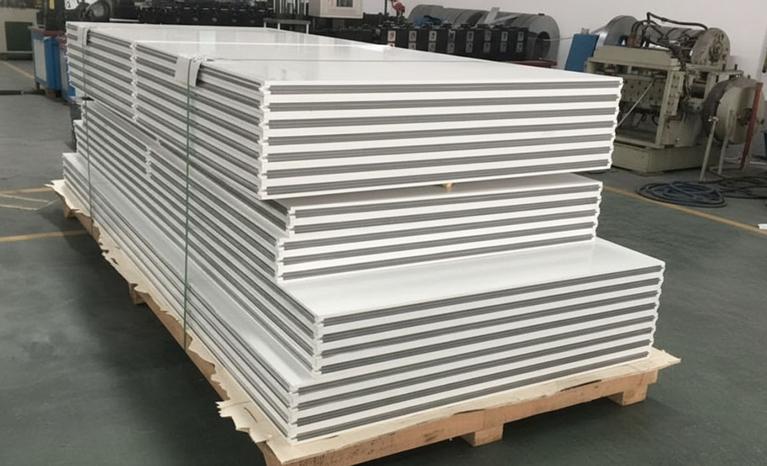
Modern cleanroom walls are typically built from sandwich panels: two thin, hard facings bonded to a lightweight core. The construction matters for a simple reason—rigidity is what keeps a wall flat. A panel that flexes under its own weight or between supports will eventually develop waves, and a wavy wall sheds cleaning effort unevenly and collects residue in the low spots. Fiberglass faces finished with gelcoat are prized here because the gelcoat cures into a flat, non-porous, waterproof skin, while steel-faced panels offer similar wipeability with higher impact resistance for heavy-traffic zones.
The uncomfortable truth, though, is that factory quality is only half the story. Panels arrive straight and sealed; rooms are built by crews working around ducts, conduits, and schedule pressure. Installation practice determines whether that factory finish survives the field: fixings must sit on the service side, never exposed on the clean side; every cable, pipe, and instrument line must pass through a dedicated sealed port rather than a cut hole stuffed with foam; and windows and doors must integrate flush into the wall plane so no jamb creates a turbulence pocket or a cleaning blind spot. Two projects can buy identical panels and end up with completely different rooms.
Coved Corners: The Small Detail That Decides the Audit
The sharpest corner in any room is the ninety-degree junction where floor meets wall—and it is the one place no mop, squeegee, or wipe cloth can properly clean. Disinfectant pools in the corner, residue builds up, and particles settle into a zone nobody can reach. Coving solves this by replacing the hard corner with a continuous concave curve, the same logic as the sealed radius inside a bathtub: the surface you stand on flows seamlessly up the wall, leaving nowhere for contamination to hide and nothing for a cleaning tool to snag on.
Getting a true monolithic cove is an installation-sequencing task, not a product purchase. The typical workflow sets the wall panels plumb first, then runs the flooring system up and into the coving profile against the wall base so floor and wall become one continuous surface. The same rounding logic is applied at wall-to-wall and wall-to-ceiling junctions. Skip this step to save a day of labor and the room will look finished—but it will carry a permanent, uncleanable line running around its entire perimeter, and a trained auditor will find it in minutes.
Airtight Joints: Why the Enclosure Has to Hold Together
A clean room is not just a tidy box—it is a pressurized box. Rooms are held at deliberate pressure relationships so air always moves from cleaner zones toward dirtier ones, and that airflow design only works if the enclosure actually contains it. Every leaky joint is a bypass route where unfiltered air sneaks across the boundary, quietly undermining the entire ventilation design no matter how powerful the air handling system is. This is why panel joints use continuous gaskets and sealant beads rather than simple butted seams, and why joint quality is treated as a performance requirement rather than a cosmetic one.
Two procurement habits separate successful projects from failed ones. First, insist on seeing joint detail drawings and sealant validation documentation before contracts are signed, because a supplier who cannot produce them is improvising. Second, confirm the sealant chemistry is compatible with the facility’s specific disinfectant agents—a sealant that swells or cracks under the site’s cleaning chemicals will fail its airtightness duty within months, long before the panels themselves show any wear.
The takeaway for anyone planning a first clean room: treat the walls, floors, and ceilings as a single continuous system, not a shopping list of materials. The smooth impervious face earns the room its class rating on paper, but the coved corners, gasketed joints, and disciplined penetrations are what keep it performing after the certification team goes home.
| Component | Material Options | Surface Requirements | Performance Criteria | Design Notes |
|---|---|---|---|---|
| Walls | GRP/FRP gelcoat panels, stainless steel sandwich panels, aluminum-faced foam core panels | Smooth, impervious, non-shedding; no ledges, recesses, or unsealed joints; coved corners at floor/wall intersections | Chemical-resistant to ≥200 disinfectant cycles (VHP/IPA/70% ethanol); airtightness <0.05 L/(m²·s) at 500 Pa differential; particle-free under wipe testing | Continuous gasketed/coved joints decide certification—not face material alone; avoid using building exterior walls due to wind pressure exceeding design differential |
| Ceilings | Flush-grid modular panels, gelcoat GRP ceiling panels, stainless steel ceiling panels with integrated HEPA diffusers | Seamless finish; fully supported suspension; no exposed grid channels that trap particulates | Load-bearing ≥15 kg/m² for maintenance access; compatible with ULPA/HEPA filter bank integration; thermal break to prevent condensation | Full-ceiling HEPA coverage recommended for ISO 5 and cleaner; raised plenum enables return air path and reduces dead zones |
| Floors | Troweled epoxy flooring (5-layer system), welded vinyl sheet flooring with PU topcoat, seamless polyurethane screed | Monolithic joint between floor and wall (cove radius ≥50 mm); no visible seams or crevices; chemically inert to cleaning agents | Spot-repairable after impact damage; anti-static option available for electronics; withstands rolling cart traffic without degradation | Epoxy preferred for chemical-intensive environments; vinyl suitable where cushion and faster installation are priorities; substrate flatness tolerance ≤3 mm over 2 m |
| Panel Joints & Penetrations | Silicone or polysulfide sealant, neoprene gaskets, coving profiles (GRP or stainless steel) | All penetrations (conduits, pipes, instrument ports) sealed with continuous bead; no exposed fastener heads on clean-side surface | Maintains specified pressure differential across joint under cyclic thermal loading; sealant compatible with facility disinfectant regimen | Audit failures most frequently occur at joint discontinuities—not panel faces; require supplier to provide joint detail drawings and sealant validation reports before procurement |
| Doors & Pass-Throughs | Solid core sandwich panel doors with gasketed frames, interlocking pass-through chambers with interlock mechanism | Door swing toward high-pressure side; no door-to-door direct alignment between adjacent clean zones | Maintains ≥7–12 Pa pressure cascade across closed door; gasket compression sufficient to prevent bypass airflow at rated differential | Class transition may only step one ISO class per anteroom; separate entry/exit routes prevent cross-contamination; avoid 12 Pa per stage across multiple doors—cumulative differential makes doors impractical to open |
Keeping People from Contaminating Clean Rooms
People — not machinery or processes — are the largest contamination source in nearly every cleanroom. Controlling them requires a layered defense: strict gowning protocols, airlocks, interlocked doors, and a pressure cascade that keeps air flowing from clean zones toward dirty ones.
Here is the uncomfortable truth every cleanroom operator must accept: the human body is a particle factory. Widely cited contamination-control benchmarks estimate that a person sitting completely still releases roughly 100,000 particles of 0.3 microns or larger every minute. Start walking, and that figure climbs to around 5 million per minute; rapid movement can push it beyond 10 million. Add skin flakes — the average person sheds tens of thousands of skin cells per minute — plus hair, textile fibers from street clothing, and respiratory droplets, and it becomes clear why contamination-control professionals treat personnel as priority number one.
Think of every person entering a cleanroom as a walking snow globe: every gesture, turn, or shuffle shakes more microscopic particles loose. No air filtration system can compensate for people moving freely in street clothes, so the defense against humans combines procedural controls (how people behave) with architectural controls (how the facility is built to channel their movement).
Gowning Protocols: The First Line of Defense
Gowning does not sterilize the person — it traps their particles inside the garment. Cleanroom apparel is made from tightly woven, lint-free fabric, and the required coverage scales with the strictness of the environment: a lab coat–style frock may suffice for looser tolerances, while the cleanest suites demand full coveralls with attached hoods, sealed wrists, dedicated knee-high boots, and goggles.
The gowning sequence itself is governed by a written SOP (Standard Operating Procedure), but most facilities share these core rules:
- No cosmetics, perfumes, or jewelry: Makeup flakes, fragrance vapors, and accessories all shed or release contaminants that garments cannot contain.
- Gown in the prescribed order, gloves last: The outermost glove surface should never be touched by bare hands, or the garment is compromised the moment it is put on.
- Change garments at fixed intervals: Depending on the cleanliness requirement, this may mean once per shift or once per entry — never “when they look dirty.”
- Move slowly during gowning: Vigorous motion in the changing area shakes particles out of street clothes and into the very space meant to keep them out.
Airlocks and Air Showers: The Transitional Buffer
A person can be perfectly gowned and still become a contamination risk at the doorway. That is why well-designed facilities never connect a cleanroom directly to an uncontrolled corridor. Instead, they insert an airlock (also called an antechamber): a small transitional room where personnel pause, complete final garment adjustments, and allow the space between the two doors to be flushed of contaminants before the inner door opens.
Many personnel airlocks add an air shower — a chamber where high-velocity, filtered air jets blow across the garment surface for a cycle of roughly 20 to 30 seconds, knocking loose particles off the suit before entry. Materials typically enter through separate pass-through chambers rather than riding alongside people, so bulk goods never overload the personnel buffer.
The airlock only works if discipline holds: one person at a time, both doors never open simultaneously, and garment adjustments finished inside the airlock — not inside the cleanroom itself.
Interlocked Doors and Pressure Cascade Logic
Doors are the weak point of any cleanroom, and two engineering principles protect them. The first is the pressure cascade: the cleanest room is held at slightly higher air pressure than its neighbor, so air constantly leaks outward — from clean to dirty. Picture a waterfall: air flows downhill, and particles cannot swim upstream. This is precisely why people are routed through progressively cleaner zones rather than stepping straight into the most critical space.
The numbers involved sound almost trivial. Guidance under ISO 14644-4 and common industry practice call for a differential of roughly 10–15 pascals (Pa) between adjacent classified rooms, and many designs specify around 15 Pa at the boundary between the cleanroom and uncontrolled space. For perspective, that is only about 0.01% of normal atmospheric pressure — yet it is enough to dictate airflow direction at every door seal, cable penetration, and wall joint. The cascade is silent, invisible, and completely dependent on the envelope staying closed.
The second principle is door swing direction. Cleanroom doors are conventionally hung to open toward the higher-pressure (cleaner) side, so the pressure differential presses the door against its gasket and actively seals it rather than pushing it outward. One practical caveat: where local fire egress codes require outward-opening escape routes, code compliance takes precedence, and the design must compensate elsewhere.
Finally, interlocked doors enforce the one-door-at-a-time rule mechanically: opening one door physically prevents the other from being released until the first is closed again. Critically, a properly designed interlock is fail-safe — on fire alarm activation or power loss, the interlock releases automatically so personnel can evacuate freely. Safety always overrides containment.
The most common self-inflicted failure in cleanroom operations is propping a door open or holding both airlock doors open during a move. A 10–15 Pa pressure cascade can collapse in seconds, letting unfiltered corridor air — and everything in it — flow straight into the clean zone. All the engineering above means nothing the moment a doorstop appears.
When planning a facility, size the gowning room generously. Undersized changing areas are the single most common trigger for gowning shortcuts — staff squeezed into a cramped space rush, skip steps, and contaminate garments before they ever reach the airlock. The gowning room is not dead space; it is the cleanroom’s first filter.
The takeaway is simple: filtration technology can only clean the air, but protocols and architecture are what govern the people moving through it. Gowning discipline stops particles at the source, airlocks create a controlled transition, interlocked doors enforce the pathway, and the pressure cascade ensures that any particle that does escape is pushed away from the product — never toward it.
Where Clean Rooms Are Used Across Industries
Clean rooms serve as critical infrastructure across semiconductor fabrication, pharmaceutical manufacturing, food processing, and new energy battery production — each industry demanding specific ISO classifications, humidity controls, and regulatory compliance frameworks.
Semiconductor and Electronics Manufacturing Requirements
Semiconductor fabrication represents the most demanding clean room application in existence. A single particle as small as 0.5 microns can destroy an entire microprocessor wafer during photolithography. This is why leading fabs operate in ISO 1 to ISO 3 environments — spaces that contain fewer than 10 particles per cubic meter at the 0.1-micron threshold.
Beyond particle control, electronics manufacturing requires strict electrostatic discharge (ESD) management. Workstations, flooring, and wall panels must all meet ESD resistance standards, typically maintaining surface resistivity between 10^6 and 10^9 ohms per square. Humidity is equally critical; maintaining relative humidity between 40% and 60% prevents static buildup while protecting sensitive components from moisture damage.
- ISO Class: ISO 1–3 for front-end wafer fabrication; ISO 4–6 for assembly and packaging
- Particle Limit: Maximum 10 particles/m³ at 0.1 µm for ISO 1; maximum 35,200 particles/m³ at 0.5 µm for ISO 6
- Temperature Control: 20°C to 22°C with ±1°C stability to prevent thermal expansion affecting nanometer-scale patterning
- Humidity Range: 40% to 60% RH to balance ESD prevention and component protection
- Air Changes: 300 to 600+ air changes per hour in ISO 5 zones; up to 1,000 ACH in ISO 4 spaces
- ESD Requirements: All surfaces, garments, and equipment must meet ANSI/ESD STM11.12 or IEC 61340 standards
The trend toward smaller process nodes — 3 nanometer and below — continues to push particle control requirements to their physical limits. Each generational shrink in transistor size demands a corresponding improvement in clean room classification, making these facilities among the most capital-intensive constructions in industrial manufacturing.
Pharmaceutical and Medical Device Production Environments
Pharmaceutical manufacturing operates under a dual regulatory framework: ISO 14644 for particle cleanliness and Good Manufacturing Practice (GMP) guidelines for microbial control. The European Medicines Agency (EMA) and the U.S. Food and Drug Administration (FDA) define four GMP grades — A, B, C, and D — each with distinct requirements for airborne microbial counts and particle limits.
Grade A represents the highest risk environment, typically applied to critical operations like filling syringes or preparing parenteral solutions. It corresponds roughly to ISO 5 conditions, requiring unidirectional laminar airflow at velocities between 0.36 and 0.54 m/s. Grade B serves as the background environment for Grade A zones, while Grades C and D cover less critical but still controlled operations such as solution preparation and component handling.
- GMP Grade A: ISO 5 equivalent; max 3,520 particles/m³ at 0.5 µm; unidirectional airflow required; microbial limit of 1 CFU/m³ for settle plates
- GMP Grade B: ISO 5 at rest, ISO 7 at active; background for Grade A operations
- GMP Grade C: ISO 7 at rest, ISO 8 at active; supports less critical manufacturing steps
- GMP Grade D: ISO 8 baseline; used for initial processing and component handling
- Surface Materials: Smooth, non-shedding, chemically resistant wall panels and coved flooring to enable rigorous disinfection protocols
- Pressure Cascade: Positive pressure differentials of 10–15 Pa between successive grades, preventing contamination ingress
Medical device manufacturing, particularly for sterile implantable devices, follows similar but not identical standards. ISO 13408 governs sterile medical device processing, often requiring ISO 5 or ISO 7 environments depending on the device risk classification. The surface finish of clean room walls and ceilings becomes a critical factor here — smooth, seam-free panel systems that resist microbial colonization are essential for maintaining compliance over extended production cycles.
Food and Beverage Hygienic Processing Zones
The food and beverage industry applies clean room principles primarily to prevent microbial contamination rather than particulate damage. While ISO classifications are less stringent than in pharmaceuticals or semiconductors, the focus on biological control — particularly against pathogens like Listeria, Salmonella, and E. coli — drives specific design requirements for hygienic processing zones.
High-care and ultra-high-care zones in food processing typically operate at ISO 7 or ISO 8 classifications. The distinction matters: high-care areas handle cooked products that receive no further sterilization before packaging, while ultra-high-care zones process ready-to-eat foods with zero microbial tolerance. These zones demand seamless wall panels with coved bases, stainless steel fixtures, and flooring that resists chemical sanitizers used in daily cleaning protocols.
- ISO Class: ISO 7 for high-care zones; ISO 8 for general hygienic processing areas
- Microbial Limits: Typically 100 to 500 CFU/m³ for settle plates in high-care areas, depending on product risk
- Temperature: 13°C to 18°C for most processed foods; 18°C to 22°C for packaging areas
- Humidity: 55% to 65% RH to prevent condensation and microbial growth on surfaces
- Wall Panel Requirements: Smooth, non-porous surfaces with integrated coving; resistant to quaternary ammonium and peracetic acid sanitizers
- Door Specifications: Self-closing, gasket-sealed doors maintaining pressure differentials between zones
Allergen control has emerged as a significant driver for clean room adoption in food processing. Facilities producing products containing major allergens — peanuts, tree nuts, soy, wheat, dairy — increasingly implement controlled environments with dedicated HVAC zoning and positive pressure barriers to prevent cross-contamination between allergen and non-allergen production lines.
New Energy and Battery Production Applications
Lithium-ion battery manufacturing, particularly for electric vehicle and energy storage applications, has become one of the fastest-growing clean room markets globally. The process demands extremely low humidity environments — typically below 1% RH for electrolyte filling and electrode coating — alongside strict particle control to prevent internal short circuits caused by metallic contaminants.
Battery cell production typically requires ISO 6 to ISO 8 environments depending on the process stage. Electrode manufacturing — where active materials are coated onto metal foils — operates in ISO 7 or ISO 8 with humidity control as the primary driver. Cell assembly and electrolyte filling demand the harshest conditions, with ISO 6 classifications and dew points as low as -40°C to prevent moisture contamination of lithium compounds.
- ISO Class: ISO 6 for electrolyte filling and cell assembly; ISO 7–8 for electrode coating and general manufacturing
- Humidity Control: Dew point of -40°C to -60°C (below 1% RH) in critical processing zones
- Particle Limits: Maximum 352,000 particles/m³ at 0.5 µm for ISO 7; maximum 3,520 particles/m³ at 0.5 µm for ISO 6
- Temperature: 20°C to 25°C with ±2°C stability to maintain material viscosity and coating uniformity
- Pressure Cascade: Positive pressure maintained throughout battery production, with increasing differential toward electrolyte filling areas
- Material Compatibility: Wall panels and seals must resist organic solvents used in electrode processing, including N-methyl-2-pyrrolidone (NMP)
The explosive growth in EV battery production capacity — with gigafactories spanning thousands of square meters of clean room space — has created unprecedented demand for modular clean room solutions. These facilities require rapid deployment, scalable designs, and construction materials that maintain integrity under continuous solvent exposure and rigorous cleaning schedules.
Conclusion
A clean room succeeds or fails on one thing: control. Your ISO 14644 class sets the particle ceiling. Your air changes per hour decide how fast you reach it. And your wall and ceiling panels determine whether the envelope holds that pressure cascade after five years of shift work, not just on validation day.
- Pick the class from your dirtiest process step, then size HVAC to match — ISO 7 typically runs 60–90 air changes per hour, ISO 8 on 20–40.
- Spec wall panels with flush, non-shedding joints and coved floor intersections — GMP auditors check those corners first.
- Design door swings and gowning flow so staff move from dirty to clean zones, never backward.
- If a layout question stalls your project, send it to our engineering team — we build these enclosures daily and will review your drawings with zero obligation.
Frequently Asked Questions
How often must a clean room be re-certified?
ISO 14644-2 requires periodic requalification, and most facilities run full particle-count and airflow tests every 6 to 12 months. GMP Grade A and B zones typically need continuous particle monitoring plus more frequent interval checks. Any modification to walls, HVAC, or layout triggers requalification regardless of the schedule. Skipping requalification voids the certification that your production license depends on.
How is a new clean room qualified?
Qualification follows ISO 14644-1 and starts with installed-filter leak testing, then airflow velocity and uniformity, room pressurization, and recovery-time tests. Particle counting follows a documented sampling plan with the number of locations calculated from the room area. For GMP facilities, the sequence runs Design, Installation, Operational, and Performance Qualification (DQ, IQ, OQ, PQ). An accredited third-party testing agency should issue the report your auditor will accept.
Do clean rooms need anti-static ESD control?
Any room handling electronics, battery electrodes, powders, or flammable solvents should control electrostatic discharge. Typical measures include static-dissipative wall, floor, and work surfaces in the 10^6 to 10^9 ohms range, grounded equipment, and ionization near critical operations. Note that relative humidity below roughly 30% sharply increases static buildup, so ESD and humidity control must be designed together. Specify dissipative panel facings at design stage rather than retrofitting coatings later.
What are clean room lighting requirements?
Cleanroom luminaires must be sealed, flush-mounted, and cleanable so they neither trap particles nor disrupt airflow patterns. Illuminance typically ranges from 300 lux in general areas to 500-750 lux at inspection and assembly stations. Ceiling fixtures must preserve the air-tightness of the ceiling plane and withstand repeated disinfectant wiping. In unidirectional flow zones, teardrop-style fixtures are used where recessed housings would disturb the airflow.
How often should cleanroom HEPA filters be replaced?
Terminal HEPA filters commonly serve 3 to 5 years, but the governing signal is the pressure drop across the filter rather than the calendar. Replace when differential pressure reaches the manufacturer’s limit, often around double the initial resistance, or when leak testing fails. Pre-filters are changed much more frequently to protect the terminal filters and extend their life. Track differential pressure readings continuously so replacement is planned rather than reactive.
Can an existing room become a clean room?
Most existing rooms can be converted if ceiling height is around 3 meters or more, the floor slab is sound, and utilities can be extended. Modular sandwich panels are erected as a freestanding or overlay envelope, avoiding demolition and reducing downtime. The usual deciding constraints are the building’s capacity to host ductwork and return-air paths, not the existing walls. A site survey of slab flatness, clear height, and power availability should precede any design work.
What documents should cleanroom panel suppliers provide?
Request third-party test reports covering fire classification, thermal conductivity (lambda value) for condensation calculations, surface chemical resistance, and flatness tolerances. For GMP projects, the supplier should also confirm that joints, coving, and sealants meet smooth, impervious, cleanable surface requirements. RaxPanel supplies certified test documentation with its gelcoat GRP/FRP and stainless steel wall and ceiling panels so planners can verify data before specification. A supplier unable to produce reports for individual materials puts your first-time validation at risk.