
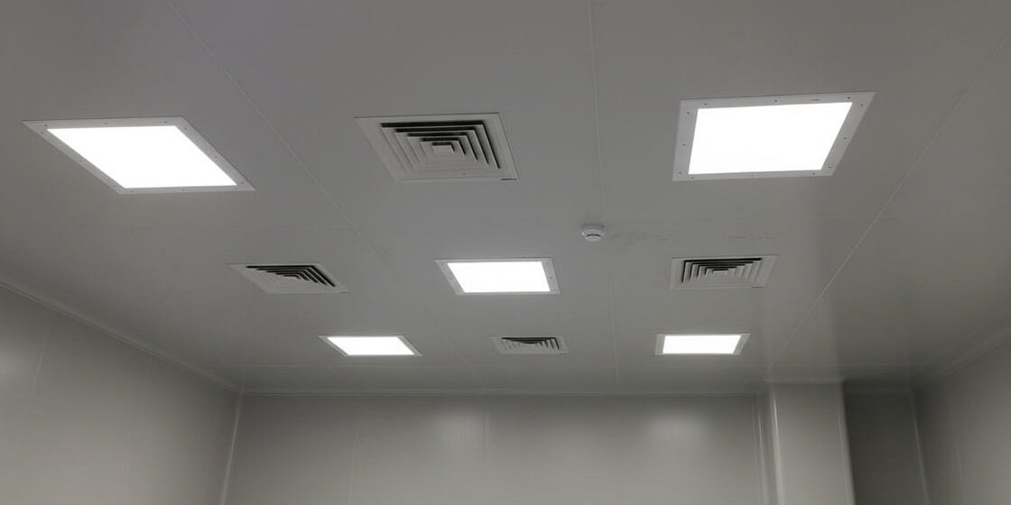
A clean room is not a very clean ordinary room. It is a machine for removing particles. Every line on its drawings exists because of one question: how does a particle get from where it is generated to where it does damage?
Design the machine by answering that question in order – generation, removal, containment, verification – and the layout almost draws itself. Design it in the reverse order, tracing a floor plan first and adding filters at the end, and you get the rooms that fail commissioning. RaxPanel supplies the wall and ceiling panels for rooms designed the first way, on programs from ISO 5 to ISO 8. Here is that purification logic in the order an engineer actually applies it.
Design Starts With the Particle, Not the Floor Plan
Every design decision downstream is driven by where particles come from and where they must not go. In most rooms the largest source walks in the door: a person in street clothing sheds on the order of a million particles per minute (trade-typical estimate). The process itself generates its own load at the worst possible place – cutting, filling or soldering happens right next to the product. Outdoor air adds a background load too, which is why supply air is filtered rather than drawn raw.
The ISO 14644-1 standard turns the target into arithmetic. Each class from ISO 1 to ISO 9 caps the permitted concentration of airborne particles, calculated as Cn = 10^N x (0.1/D)^2.08, where D is the particle size in microns. In practical terms, ISO 5 allows 3,520 particles per cubic metre at 0.5 microns and larger. ISO 8 allows 3,520,000 – a thousandfold spread that the whole cleanroom classification system expresses on one logarithmic scale.
So the first line of a clean room design is never a wall. It is the class the process demands, written down with the particle size threshold attached. Our classification definitions guide covers that vocabulary, and the selection guide maps classes to processes. Everything after this point is physics applied to that number.
Let the Class Set the Air: ACH and Flow Pattern
Two removal mechanisms exist, and the class chooses between them. Dilution floods the room with filtered air and lets mixing carry particles to low-level returns. Sweeping moves air in one direction, ceiling to floor, carrying particles away from the product before they can wander – that is unidirectional flow.
Each mechanism has its numbers. Trade-typical dilution rates run 20 to 60 air changes per hour and serve ISO 7 and ISO 8 rooms. Trade-typical unidirectional velocities run 0.3 to 0.5 metres per second, and ISO 5 and cleaner rooms demand the sweeping pattern. Pick the wrong mechanism and no amount of filter area rescues the class.
The two patterns can be combined inside one room. A turbulent-mixed ISO 7 assembly area can carry laminar-flow zones over the part of its ceiling where the critical step happens. This is the most cost-effective idea in clean room design: buy sweeping coverage only where the product is exposed, and let mixed flow handle the rest of the volume.
For the buyer, the airflow decision shows up concretely in the quotation. More air changes mean larger fans, deeper AHU sections, bigger filter area and a permanently higher power bill. A full unidirectional ceiling on an ISO 8 room is money spent sweeping air that never touches the product. Ask each bidder to state the assumed ACH and the reasoning behind it, then compare five-year energy figures rather than capital cost alone.
Filtration Is a Chain, Not a Filter
A single HEPA panel facing a dusty duct clogs in weeks, so purification is staged. Prefilters catch the coarse load. Bag or medium filters take the fine fraction. Terminal HEPA filters see only the residue, rated 99.97 percent or better at 0.3 microns – the threshold that defines HEPA under the US DOE standard. Each stage protects the next, and the cheapest filters do the heaviest work.
The staging logic drives real design decisions. Filter housing needs access space above the ceiling grid. Integrity-test ports need to be reachable for certification. The air handling train needs surface area sized for the dust load the process actually generates, not a catalogue default. Rooms that skip staging pay for it twice: in filter replacement frequency and in the downtime of every certification failure.
One filtering question belongs in the specification stage rather than the procurement stage. For most ISO 5 to ISO 8 programs, HEPA terminal filters are the correct ceiling. Asking for ULPA there buys pressure drop and fan energy without changing the class the room can hold. ULPA earns its place in ISO 3 to ISO 5 semiconductor and pharmaceutical aseptic suites, where the particle sizes that matter sit below what HEPA captures efficiently. Decide this from the process requirement, before a salesman decides it for you.
RaxPanel supplies cleanroom wall and ceiling panels for design programs from ISO 5 to ISO 8. Send your class target and process type – an engineer returns panel specifications within 24 hours, one to one.
Pressure Cascade: Routing the Air Before Routing People
Containment is the third principle: air should always leak from cleaner toward dirtier, never the reverse. Adjacent zones are held at a differential of trade-typically 10 to 15 pascals, cleanest zone highest. Any leakage through door gaps or panel joints then flows outward, carrying particles away from the product. The cascade is why a cleanroom door hisses when it opens – that audible draft is the gradient doing its job, door after door, all shift long.
Designing the cascade means drawing the pressure map before the traffic map, because the two must agree. Airlocks, gowning rooms and pass-through chambers are the gradient’s gearboxes. Each staged step keeps any single door opening from dumping the differential. Where a process handles hazardous material the cascade reverses – negative pressure holds contamination in – and the same staging logic applies in mirror image.
Layout That Follows the Air
With generation, removal and containment set, the floor plan becomes a consequence rather than a starting point. Material moves from dirty to clean through its own airlock or pass-through. Personnel gown through a sequence of pressure steps. Flow direction runs one way, from the cleanest zone toward the exit, because two flows that cross in a corridor will defeat everything the HVAC system did an hour earlier.
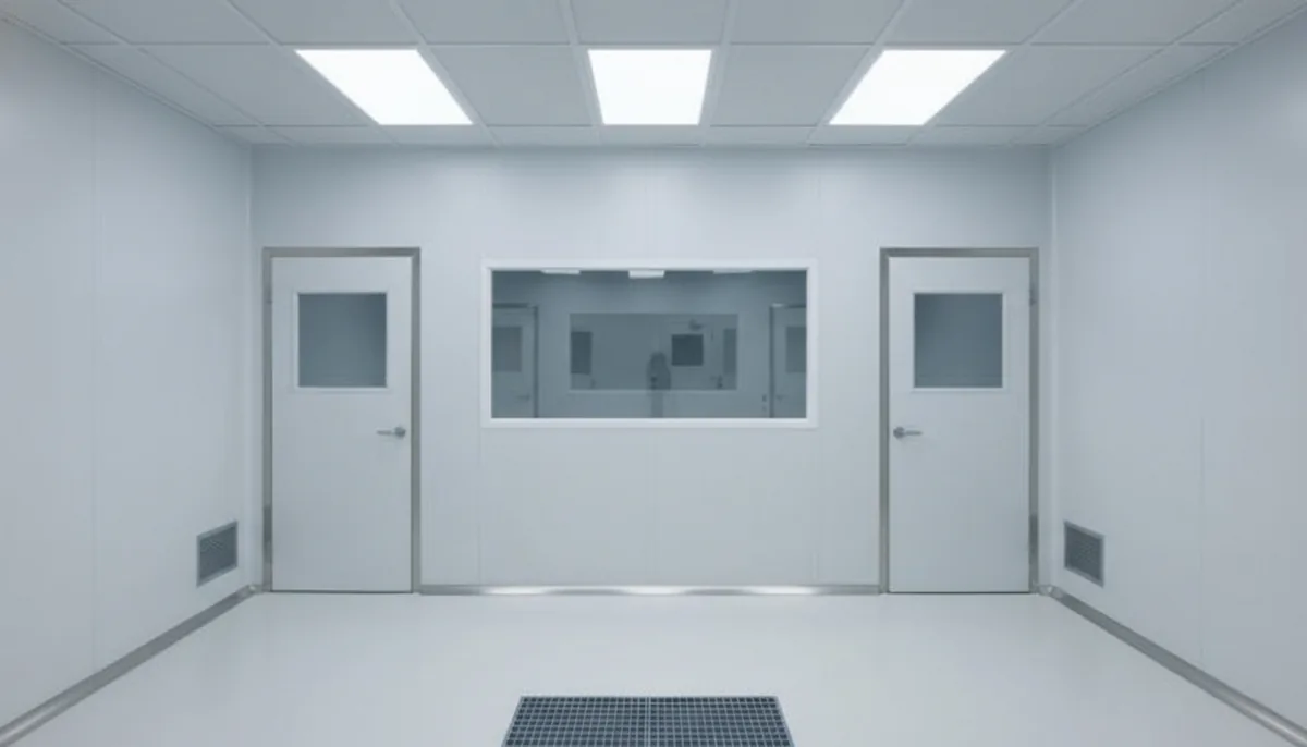
The envelope materials close the chain. Walls and ceilings must not shed particles, must wipe clean, and must hold sealed joints so the pressure cascade does not leak through the building fabric itself. RaxPanel supplies cleanroom wall and ceiling panels for exactly this role, in GRP-faced, steel-faced and honeycomb formats matched to the chemicals and traffic of the process behind them.
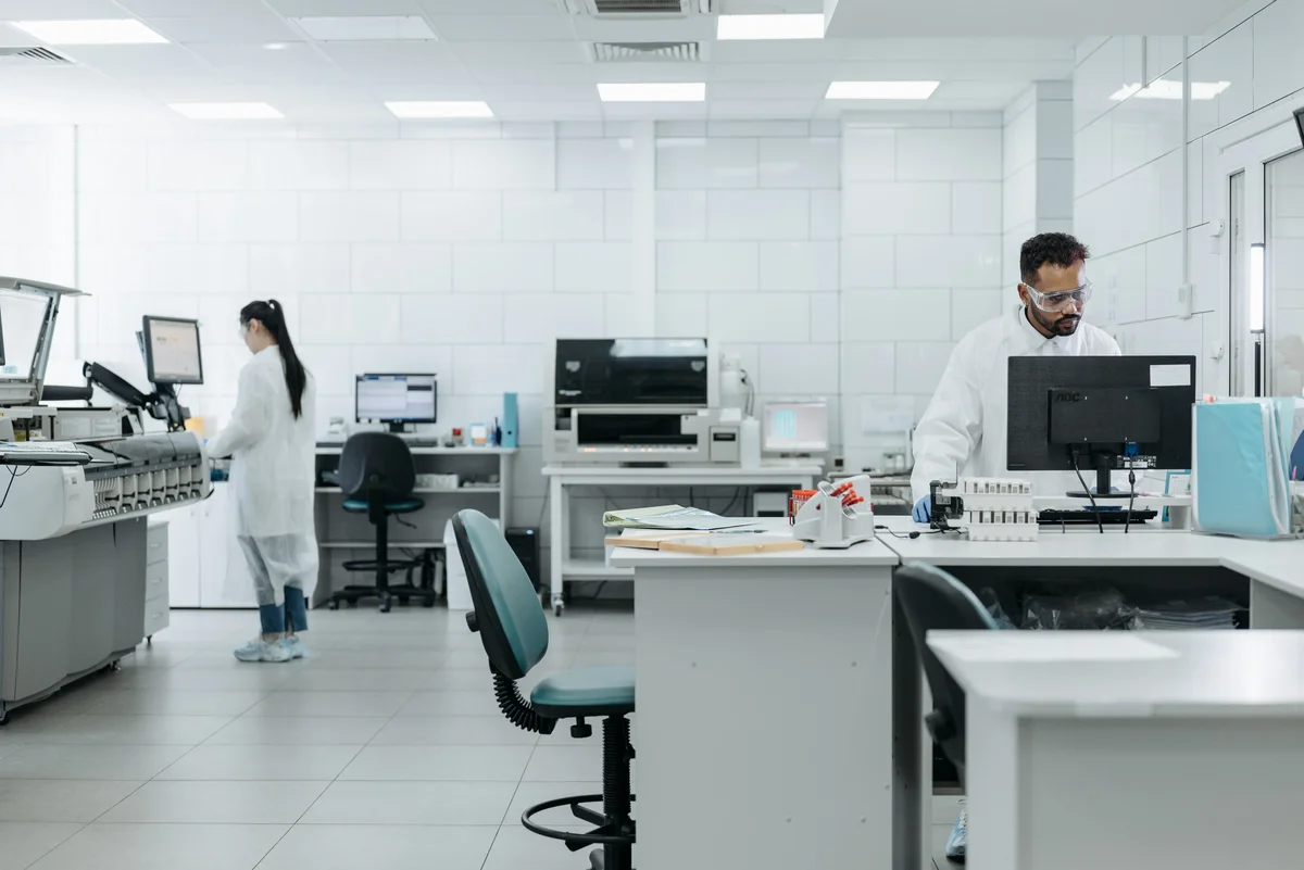
Height is part of the layout too. Ceiling filter coverage, return air paths at low level and service space above the grid compete for the same section. A room that steals plenum height to gain floor area often ends up re-buying fans. The same air changes must then be pushed through a smaller filter face – a trade worth pricing before the steelwork is ordered.
Design check: walk the plan on paper from door to product, for people and for materials separately. Every threshold crossed should appear on the pressure diagram as a step, and no step should be crossed twice. Any crossing you cannot draw cleanly is a contamination path waiting for an auditor to find.
Prove the Design Works Before Panels Ship
A purification design earns belief at commissioning, not at drawing approval. Smoke tubes show whether sweeping actually reaches the product or stalls in eddies behind equipment. Particle counts test the class at rest and in operation, the two states EU GMP grading distinguishes. Filter integrity scans find the leak one housing seal missed. Each test maps to a clause of the ISO 14644-3 test methods, and each should appear in the contract with an acceptance value before fabrication starts.
| Commissioning test | What it proves | Typical method |
|---|---|---|
| Airflow visualization | No stagnation or eddies at critical points | Smoke tube study, video record |
| Airflow velocity / ACH | The design air changes are really delivered | Anemometer traverse at filter face |
| Filter integrity | No bypass leaks in HEPA installation | PAO scan per ISO 14644-3 |
| Particle count | The room holds its class in operation | ISO 14644-1 sampling plan |
| Pressure cascade | Gradient survives door movement | Differential gauge, doors open/closed |
Design the monitoring points at the same time as the room. Sample ports belong at the critical process locations, not the return duct where air is cleanest. Alarm thresholds belong below the class limit, so the trend breaks while correction is still cheap. A design that cannot show its own data is a design still unfinished – see our guide to cleanroom requirements for the requalification intervals that follow handover.
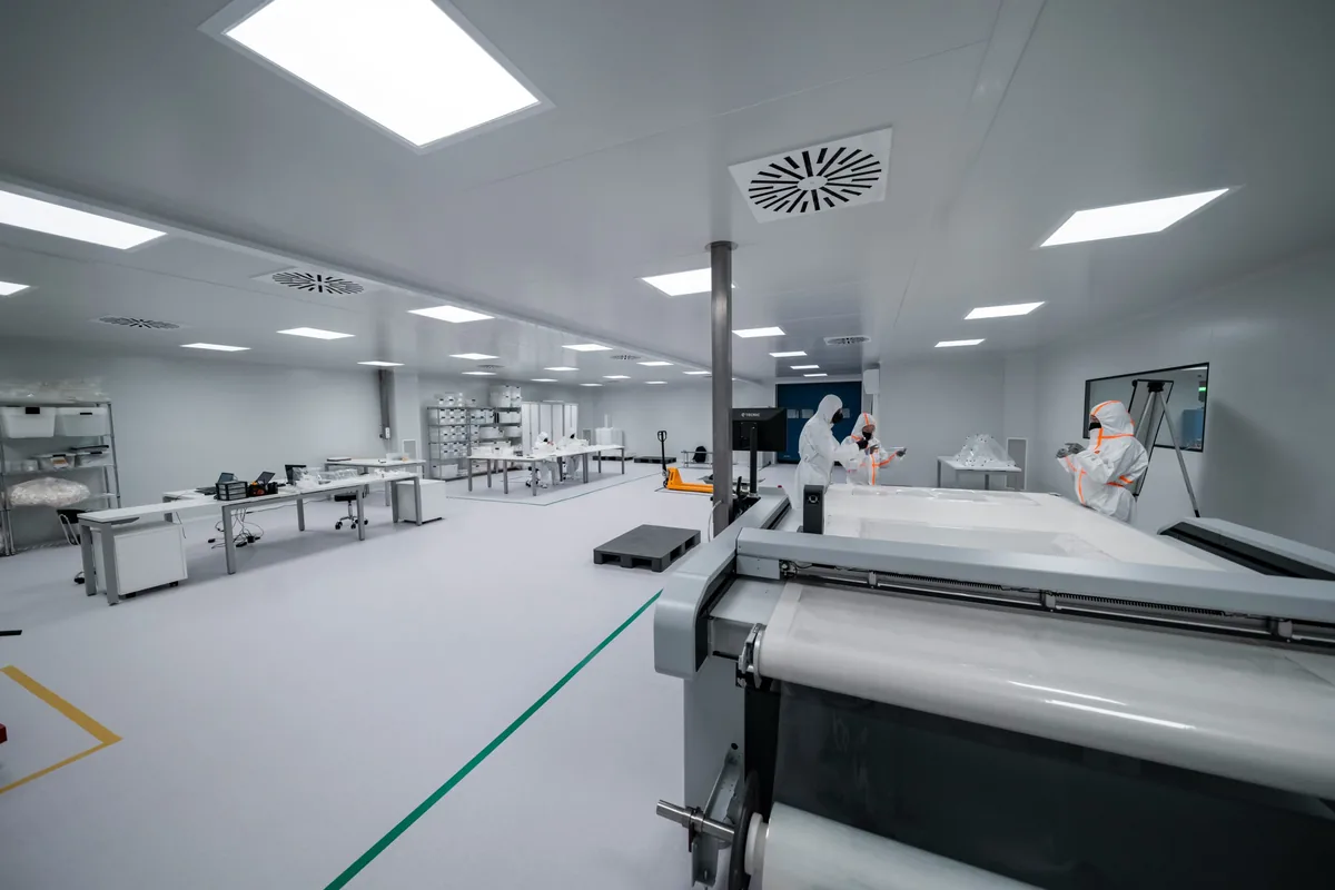
Worked end to end, the purification logic gives a buyer five things to demand from any supplier. First, a stated class with particle thresholds; second, an ACH and flow-pattern calculation behind the quotation; third, a staged filtration train with testable access. Fourth, a pressure map that agrees with the traffic plan; fifth, a commissioning test list with acceptance values.
A supplier who produces all five has designed a machine. One who produces a floor plan with filters has drawn a room and hoped.
Frequently Asked Questions About Clean Room Design
What is the first step in clean room design?
Fix the cleanliness class the process requires, with its particle size thresholds, per ISO 14644-1. Every later decision – airflow pattern, ACH, filtration staging, pressure cascade, panel specification – is derived from that number.
What is the difference between unidirectional and turbulent airflow?
Unidirectional flow sweeps air in one direction at 0.3 to 0.5 m/s, carrying particles away from the product. Turbulent (mixed) flow dilutes contamination through room-wide mixing at 20 to 60 ACH, typical for ISO 7-8 rooms.
Why does a clean room need a pressure cascade?
Adjacent zones held at a 10-15 pascal differential, cleanest highest, force any air leakage to flow from clean toward dirty. Without the gradient, door openings pull contaminated air back across the product.
How are filters staged in a clean room?
Prefilters catch coarse dust, medium filters take the fine fraction, and terminal HEPA filters – 99.97 percent efficient at 0.3 microns – handle only the residue. Staging extends filter life and protects certification results.
How is a clean room design verified?
At commissioning: smoke-tube airflow visualization, air change measurement, PAO filter integrity scanning, particle counting in operation, and cascade checks. Each carries a contractual acceptance value.