
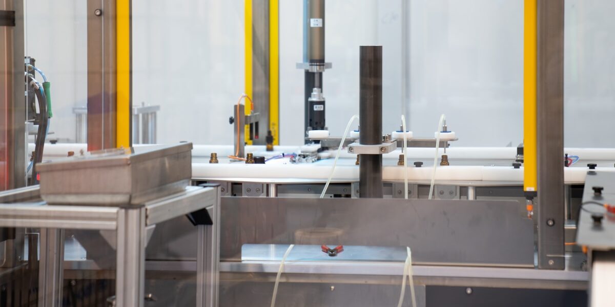
Certification failures are almost never surprises on test day — they are the accumulated result of design shortcuts made months earlier. It starts on paper, when somebody copies an air change rate out of a reference table instead of engineering it around the process inside the room. An ISO 7 clean room typically runs 30 to 60 air changes per hour. Treat that range as a blind target and you oversize the air handler — and pay for it in energy for the next twenty years — or undersize it and spend production shifts chasing particles you can never quite clear.
The purification principles behind that number are fewer than most first-time builders fear. Airflow sweeps: dilution carries particles out of the room at a rate you can calculate and defend. Filtration catches: HEPA and ULPA media trap what the airflow delivers, in the sub-micron range where the eye is useless. Pressure guards the boundary — a cascade between adjacent rooms, held at fractions of an inch of water gauge, forces contamination to move in one direction only: out. Master the logic connecting those three, and the tables stop being guesses.
Construction choice shapes all of it, so we close on modular versus stick-built — the decision that sets your schedule, your panel interfaces with fixed equipment, and a large share of your lifecycle cost. At RaxPanel we manufacture the wall and ceiling panel systems on the modular side of that comparison, and years around these builds point to one pattern: the rooms that pass validation on the first attempt belong to designers who understood these principles before the first panel went up. Internalize them, and you walk into commissioning as the person asking the hard questions — not the one answering them.
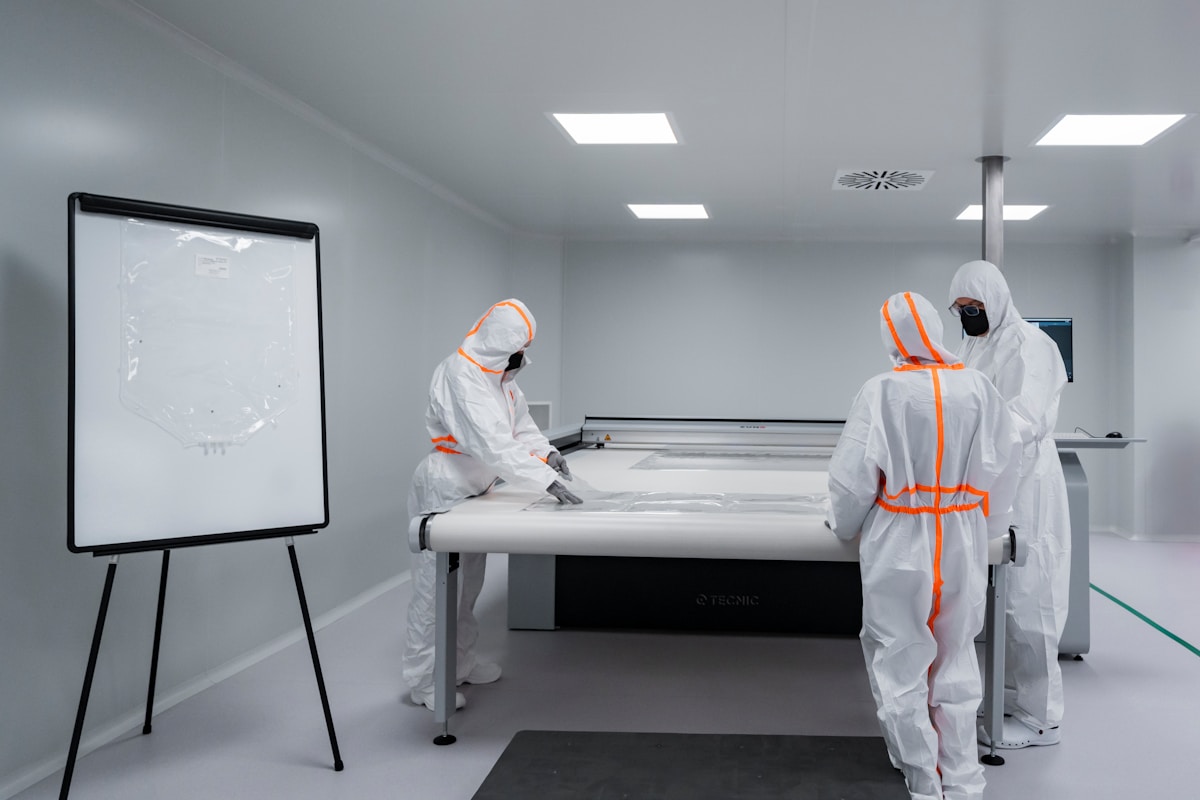
What Is a Clean Room and Why Purification Matters
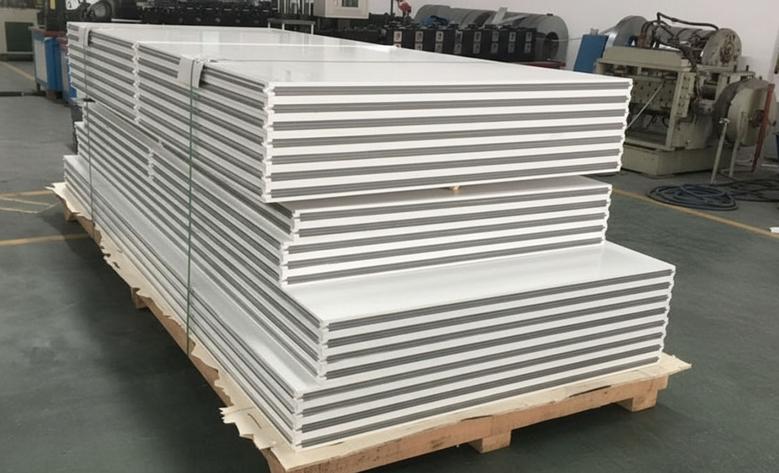
Key Takeaways: A clean room is an enclosed space where particulate and microbial concentrations are controlled below naturally occurring levels. Outdoor air can exceed 35 million particles ≥0.5µm per cubic meter, while an ISO 8 cleanroom permits only 3,520,000 particles per cubic meter. Purification achieves this through HEPA/ULPA filtration, laminar airflow, and an airtight envelope—where our GRP/FRP sandwich panels with PIR or honeycomb cores provide the critical sealed boundary that makes the system physically possible.
A clean room is not simply a “very clean room.” It is a controlled environment where the concentration of airborne particles and microorganisms is kept below a specified threshold, as defined by ISO 14644-1. The purpose is to protect sensitive processes—from semiconductor fabrication to aseptic pharmaceutical filling—from contamination that would otherwise be introduced by unfiltered air, shedding materials, or human activity.
To grasp why purification matters, compare the air you breathe outdoors with the air inside a controlled environment. On a typical day, outdoor air contains roughly 35 million to 100 million particles ≥0.5µm per cubic meter. Even a low-grade ISO 8 cleanroom reduces that number to 3,520,000 particles per cubic meter—a tenfold to thirtyfold reduction. An ISO 5 room (used in critical drug-fill operations) demands no more than 3,520 particles per cubic meter, a reduction of four to five orders of magnitude. That gap is bridged entirely by engineered air-handling and envelope integrity.
How Purification Systems Remove Contaminants
The three pillars of cleanroom air control are filtration, airflow management, and a sealed envelope. HEPA filters capture 99.97% of particles at 0.3µm; ULPA filters push that to 99.999% at 0.12µm. Airflow is designed to sweep particles away—either through turbulent dilution (high air-change rates in lower ISO classes) or unidirectional laminar flow (low turbulence in ISO 5 and above). But none of this works if unfiltered air infiltrates through gaps, seams, or penetrations.
This is where the physical envelope becomes the limiting factor. Our engineers specify cam-lock tongue-and-groove joints with continuous gaskets on GRP/FRP sandwich panels because leakage concentrates at panel interfaces. When we test joint systems at 50 Pa differential pressure, a well-sealed panel wall achieves an air-leakage rate of 1–2%. If the joint is poorly designed, leakage can exceed 10%, forcing the HVAC system to work harder just to maintain pressure cascade—and still failing particle-count validation.
We also factory-integrate flush service chases for lights, detectors, and sprinklers. Field-cut penetrations are the most common source of post-installation leakage and particle shedding. By pre-engineering panel cutouts before shipment, we eliminate the number-one cause of re-validation surprises in year one.
Why Contamination Control Matters Across Industries
The cost of contamination is measured in scrapped product, failed audits, or patient harm. In pharmaceutical manufacturing, a single breach of GMP-grade air cleanliness can invalidate an entire batch. In semiconductor fabrication, a particle larger than the process node can destroy a wafer. In medical-device assembly, microbial contamination leads to device rejection and regulatory warning letters.
But the envelope also carries hidden lifecycle costs. Panel thermal conductivity and airtightness directly size the HVAC capital expense. A PIR- or honeycomb-core sandwich panel with low thermal conductivity reduces condensation risk at internal surfaces, cuts heating and cooling loads, and shrinks the fan and filter bank required to achieve the necessary air changes per hour. Finance teams approve projects faster when the envelope choice is tied to a quantifiable reduction in lifetime energy per cubic meter of filtered air.
Across industries—from aseptic filling to aerospace composites curing—the cleanroom is only as strong as its weakest joint. Specifying the panel system first, and treating the HVAC and filtration as a consequence of that envelope, is the engineering approach that passes ISO 14644-2 validation on the first attempt.
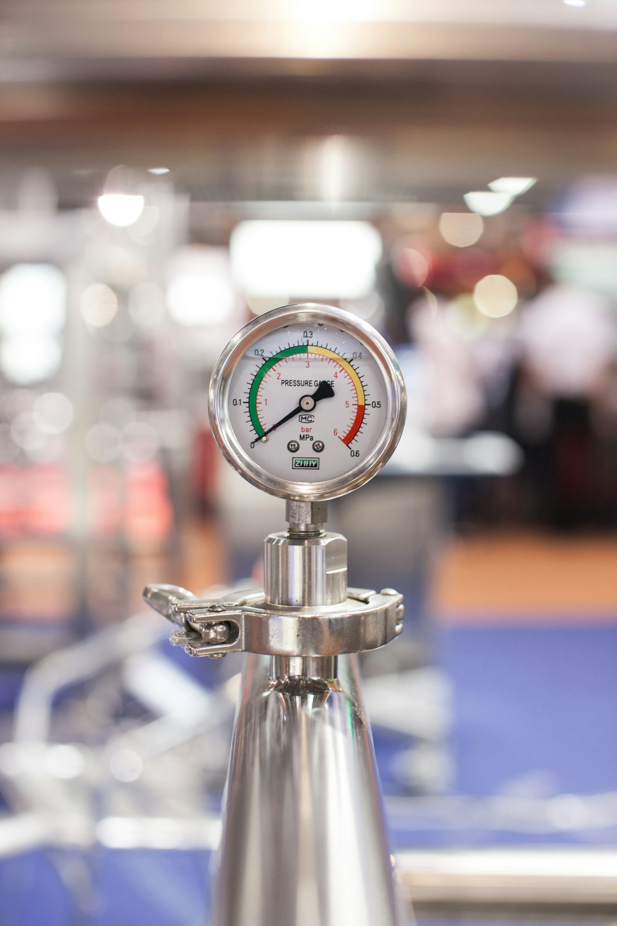
Understanding ISO Clean Room Classification Standards
Clean room classification is governed by the international standard ISO 14644, which defines cleanliness levels based on the concentration of airborne particles within a controlled environment. The standard divides clean rooms into classes ranging from ISO 1 (the cleanest) to ISO 9 (the least clean), with each class specifying the maximum allowable particle count per cubic meter of air.
The ISO 14644 framework replaced earlier national standards such as the U.S. Federal Standard 209E, providing a globally consistent methodology. Classification is determined through particle counting tests conducted under specific conditions, and it applies to both new installations and ongoing compliance monitoring.
How ISO Classes Are Defined
Each ISO class corresponds to a maximum particle concentration limit measured at specific size thresholds—typically 0.1 μm, 0.2 μm, 0.3 μm, 0.5 μm, 1.0 μm, and 5.0 μm. The class number itself roughly correlates to the number of particles of size 0.5 μm and larger per cubic foot in the old Federal Standard 209E system, though the calculation method differs under ISO 14644.
- ISO Class 3: Suitable for ultra-high-precision semiconductor fabrication and aerospace component assembly.
- ISO Class 5: Commonly required for sterile pharmaceutical manufacturing and sensitive optical work.
- ISO Class 7: Frequently specified for medical device assembly and general pharmaceutical operations.
- ISO Class 8: Used in food processing, cosmetic manufacturing, and supporting areas within healthcare facilities.
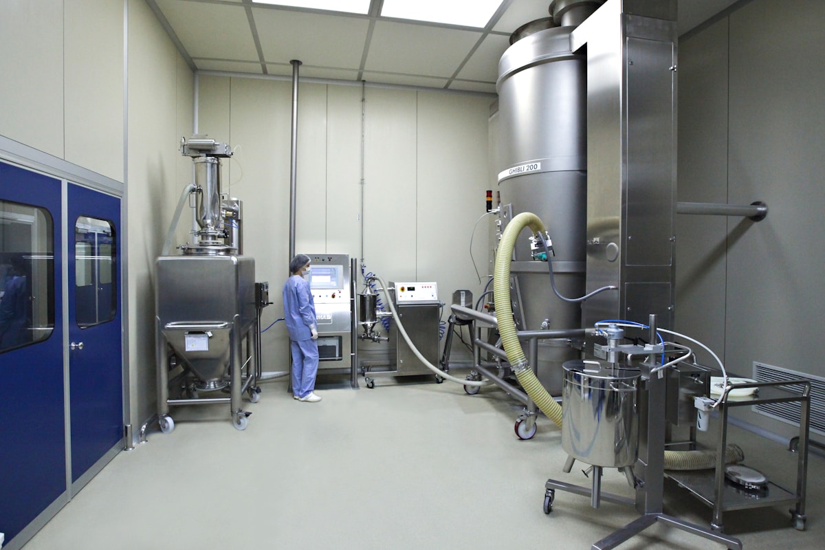
Key Terms for Air Change Rates and Filtration Grades
Air Changes per Hour (ACH)
Air Changes per Hour (ACH) measures how many times the total volume of air in a clean room is replaced with filtered air within one hour. It is a fundamental design parameter that directly influences the room’s ability to dilute and remove airborne contaminants. Higher ACH values are required for stricter ISO classes, particularly in environments where contamination sources are active or frequent.
ACH calculations depend on the supply airflow volume divided by the room’s internal volume. A typical ISO Class 7 clean room may operate at 30 to 60 air changes per hour, while an ISO Class 5 environment can require several hundred ACH, often achieved through laminar flow arrangements.
Filtration Grades: HEPA and ULPA
HEPA (High-Efficiency Particulate Air) filters are the industry standard for clean room air purification. A true HEPA filter, as defined by EN 1822 and equivalent standards, must capture at least 99.97% of airborne particles at the Most Penetrating Particle Size (MPPS) of approximately 0.3 μm.
ULPA (Ultra-Low Penetration Air) filters provide an even higher level of filtration, capturing 99.999% of particles at 0.12 μm. ULPA filters, such as the U15 grade, are standard for ISO Class 5 and below, where sub-micron particle control is critical.
- HEPA (H13): 99.95% efficiency at MPPS — suitable for ISO Class 6 to ISO Class 8.
- HEPA (H14): 99.995% efficiency at MPPS — suitable for ISO Class 6.
- ULPA (U15): 99.9995% efficiency at MPPS — suitable for ISO Class 3 and above.
Essential Vocabulary for Clean Room Pressure and Airflow
Pressure Differential
Pressure differential refers to the controlled difference in air pressure between adjacent clean room zones. It is typically measured in Pascals (Pa) or inches of water column (in. wg). Positive pressure means the clean room is pressurized relative to adjacent spaces, preventing contaminated air from entering. Negative pressure isolates hazardous materials or pathogens within a room, protecting the outside environment.
Minimum pressure differentials between classes are generally specified at 0.02 to 0.05 inches of water gauge, which corresponds to approximately 5 to 12.5 Pa, though some regulations require higher values for critical processes.
Airflow Patterns
The two primary airflow configurations in clean room design are unidirectional (laminar) and non-unidirectional (turbulent).
- Unidirectional Flow: Air moves in parallel streamlines at a consistent velocity, typically sweeping contaminants directly out of the space. Used in ISO Class 1 through ISO Class 5 environments.
- Non-Unidirectional Flow: Air mixes turbulently, relying on dilution and filtration to maintain cleanliness. Common in ISO Class 6 through ISO Class 8 environments.
Supply and Exhaust Air
Supply air is the conditioned, filtered air introduced into the clean room, usually delivered through HEPA or ULPA filter banks in ceiling plenums. Exhaust air is the contaminated air removed from the space, often returned through return air grilles located at lower wall positions to facilitate proper air sweep patterns.
Common Metrics for Particle Size and Concentration Limits
Particle Size Classification
Particle size in clean room contexts is measured in micrometers (μm), also called microns. One micrometer equals one-millionth of a meter. The most relevant size ranges for clean room classification are 0.1 μm (sub-micron), 0.5 μm (the standard reference size in ISO 14644-1), and 5.0 μm (large particles that can settle on product surfaces).
Concentration Limits
Particle concentration is expressed as the maximum number of particles per cubic meter of air at each specified size. ISO 14644-1 provides a mathematical formula for calculating these limits:
Cn = 10^N × (0.1/D)^2.08, where Cn is the maximum particle concentration limit, N is the ISO class number, and D is the particle size in micrometers.
- ISO Class 5: Maximum 3,520 particles per m³ at 0.5 μm — roughly equivalent to 100 particles per cubic foot under the old Federal Standard 209E.
- ISO Class 7: Maximum 352,000 particles per m³ at 0.5 μm — allowing significantly more airborne contamination than Class 5 but still highly controlled.
- ISO Class 8: Maximum 3,520,000 particles per m³ at 0.5 μm — the least stringent class, suitable for lower-risk manufacturing operations.
Additional Key Terms
- Settled Particles: Particles that have deposited on a surface due to gravity. Measured separately from airborne particles using settle plates or surface sampling.
- Non-Volatile Residue (NVR): The residue left on a surface after a liquid sample has evaporated, used to quantify surface contamination in pharmaceutical clean rooms.
- Recovery Time: The time required for a clean room to return to its target particle concentration after a contamination event, such as opening a door or introducing a new process.
- Background Room: The adjacent non-clean or less-clean area surrounding the clean room, which serves as an anteroom or buffer zone to reduce contaminant ingress.
How Airflow Sweeps Away Contamination
Airflow is the primary mechanism for contamination control in clean rooms. By moving air in a controlled, directional pattern at sufficient volume, particles are physically swept out of the space before they can settle on critical surfaces.
Airflow pattern, velocity, and volume — not just filter quality — determine whether a clean room meets its particle count targets. This is why some clean rooms maintain ISO Class 3 conditions while others, with identical filtration, still fail particle count requirements.
Unidirectional (Laminar) vs. Non-Unidirectional (Turbulent) Airflow
so it’s worth taking a closer look at how each flow type behaves and where each one is used.
In laminar airflow, air moves in parallel layers with minimal disruption between them. Think of it like a smooth river — every water molecule travels in the same direction at roughly the same speed. In a clean room, this means filtered air moves uniformly from the supply side (typically a full-ceiling HEPA/ULPA filter bank) toward the return side (usually low wall grilles). Contaminant particles are carried along with the air stream and pushed directly out of the room, never given the chance to settle or accumulate.
Laminar flow can be arranged vertically (air moves top-to-bottom) or horizontally (air moves side-to-side). Vertical laminar flow is more common in modern clean rooms because it directs contaminants away from the work surface and down toward floor returns, reducing the chance that particles will drift over sensitive processes. Horizontal laminar flow is still used in certain applications, particularly where large equipment must pass through the room.
In turbulent (non-unidirectional) airflow, air moves in irregular, mixing patterns with varying velocities. While this type of airflow is acceptable for less stringent clean room classifications, it does not actively sweep particles out of the space. Instead, it relies on dilution — constantly introducing filtered air to gradually reduce particle concentration. Turbulent airflow can allow particles to linger, recirculate, or settle temporarily before being diluted out.
- Unidirectional (laminar) flow is required for ISO Class 1 through 5. Air moves in straight, parallel paths at a typical velocity of 0.45 m/s (±20% per ISO 14644-3). This airflow actively sweeps particles out of the controlled space rather than relying on dilution.
- (empty — block content merged into Block 119 and this duplicate removed)
Air Change Rates and the Dilution Principle
“”
The dilution principle works like this: every time the HVAC system pushes fresh filtered air into the room, it mixes with the existing air and lowers the overall particle concentration. The more frequently the air is replaced, the lower the particle count. This is why higher ISO classifications require significantly more air changes per hour.
While specific ACH requirements vary based on room size, occupancy, and process activities, the general relationship follows ISO 14644-1 guidelines: ISO Class 8 clean rooms may operate with 10–25 ACH, while ISO Class 7 environments typically require 30–60 ACH. ISO Class 5 spaces that use turbulent airflow (rare but possible in certain retrofit scenarios) may require 200–500+ ACH to achieve the same particle control that laminar flow achieves at a fixed 0.45 m/s face velocity.
The Sweep Mechanism: How Particles Are Physically Removed
The most intuitive way to understand contamination control is to visualize what happens to a single particle in a clean room. When that particle is generated — whether from a person moving, a process operation, or air entering through a doorway — it needs a path to leave the controlled space. Airflow provides that path.
In a properly designed unidirectional clean room, the mechanism is straightforward: HEPA-filtered air enters uniformly across the entire ceiling, moves straight down (or across) at a controlled velocity, and carries all suspended particles with it. The air then exits through return grilles located along the lower walls. Particles have nowhere to go but out. There is no recirculation zone, no dead air pocket, and no opportunity for contaminants to settle on work surfaces.
In a turbulent clean room, the mechanism is less direct. Filtered air is introduced at higher velocity through diffusers, creating mixing patterns that gradually dilute the particle concentration throughout the room. Returns are typically located at ceiling level or high on walls. The cleaning action is statistical rather than mechanical — over time, the ratio of clean air to contaminated air increases, and the overall particle count drops. However, during that transition period, particles can temporarily accumulate in low-velocity zones or near obstacles.
When evaluating a clean room design, always ask whether the airflow pattern is unidirectional or turbulent. A room with excellent HEPA filtration but poor airflow design will still fail particle counts. Filtration removes particles from the air supply — airflow determines whether those particles are actually removed from the room.
Key Design Factors That Determine Sweep Efficiency
Achieving effective contamination sweep is not just about having enough filtered air. Several interdependent factors determine whether airflow will perform as intended:
- Airflow Velocity: In laminar flow clean rooms, the standard face velocity is 0.45 m/s (90 fpm). Too slow, and particles settle before being swept out. Too fast, and turbulence is introduced, breaking the laminar pattern. ISO 14644-3 specifies the acceptable tolerance band around this velocity.
- Supply-to-Return Ratio: The volume of air entering must closely match the volume returning. Significant imbalance creates positive or negative pressure conditions that can either force contaminated air out through door gaps or draw unfiltered air inward — both undermining the sweep mechanism.
- Return Air Placement: Low wall returns are essential for vertical laminar flow, allowing particles to travel the full distance to the exhaust. Ceiling returns work better for horizontal laminar flow or turbulent systems but can create short-circuiting if not properly positioned.
- Obstruction Management: Equipment, workstations, and storage inside the clean room must not disrupt the airflow path. Even a small obstacle can create recirculation zones where particles accumulate — a phenomenon known as a “dead zone.”
- Filter Coverage: In unidirectional rooms, the HEPA or ULPA filter bank should cover 100% of the ceiling area (or the full cross-section for horizontal flow). Any gap between filters or between the filter frame and the ceiling allows unfiltered air to bypass the sweep pattern.
Many buyers focus exclusively on filter grade when specifying a clean room, assuming that a higher-rated filter automatically means better contamination control. This is a common misconception. A Class 100 (ISO 5) room built with proper unidirectional flow, sufficient air changes per hour, and standard HEPA filtration will consistently outperform a poorly designed room that relies on ULPA filters but lacks correct airflow, because even the finest filter cannot compensate for an air pattern that fails to sweep particles away from the work surface. The airflow pattern is the primary control mechanism; filtration is the secondary support system.
How Contamination Sources Interact with Airflow
Sweep mechanics cannot be understood in isolation from contamination sources. In any clean room, the dominant particle sources are human occupants (typically 60–80% of generated particles), followed by processes and equipment (15–30%), and building structure or air infiltration (5–15%).
When a person moves in a clean room, they generate a wake of turbulent air that lifts particles from their clothing, skin, and movements. In a laminar flow room, this wake is quickly aligned with the main air stream and swept toward the return. In a turbulent room, the wake can persist and interact with other air currents, potentially keeping particles suspended for extended periods.
This is why clean room gowning procedures and movement protocols exist — not just to reduce particle generation at the source, but to minimize the disruption to the designed airflow pattern. Even the best airflow design can be compromised by excessive human activity or improper work practices.
Practical Implications for Clean Room Selection
For buyers evaluating clean room solutions, the airflow strategy should be one of the first design decisions — not an afterthought. The choice between unidirectional and non-unidirectional airflow affects everything from HVAC sizing and energy consumption to ceiling height requirements and construction costs.
- Unidirectional flow rooms require higher ceiling structures to accommodate full-area filter banks and sufficient plenum space. They also consume more energy due to continuous high-volume fan operation, but they provide the most reliable and consistent contamination control.
- Turbulent flow rooms are more flexible in terms of building integration and typically have lower first costs and energy consumption. They are suitable for ISO Class 7 and 8 applications where the particle load is moderate and the consequences of a temporary particle excursion are low.
- Hybrid approaches are increasingly common, where unidirectional flow is provided over critical work zones (ISO Class 5 or 6 workstations) within a larger turbulent-flow clean room. This optimizes both performance and cost.
The bottom line is that moving air is the first and most important cleaning tool in any clean room. Filtration cleans the air that enters the room. Pressure differentials keep contaminated air from entering. But it is the airflow pattern and volume that actually removes the particles that are already inside. Any clean room design that neglects these principles — regardless of how sophisticated its filtration system may be — will struggle to meet its stated classification.
What HEPA and ULPA Filters Actually Do
HEPA and ULPA filters are the primary defense against airborne contamination in clean rooms. They work by physically trapping particles through three mechanisms—diffusion, interception, and impaction—rather than simply “filtering like a sieve.”
The 0.3-Micron Benchmark: Why It Matters
When you see a HEPA filter rated at “99.97% at 0.3 microns,” that 0.3-micron number is not arbitrary. It represents the Most Penetrating Particle Size (MPPS)—the particle size that is hardest for the filter to capture. Particles larger than 0.3 microns are caught more easily by impaction and interception. Particles smaller than 0.3 microns are caught more easily by diffusion. The 0.3-micron size sits at the difficult middle ground.
This means a HEPA filter’s rated efficiency at 0.3 microns is actually the worst-case scenario for particle penetration. If it captures 99.97% of the hardest-to-trap particles, it captures significantly higher percentages of both larger and smaller particles.
Three Mechanisms Behind the Filtration
HEPA and ULPA filters do not work by straining particles like a kitchen sieve. Air flows through a mat of randomly oriented fiberglass fibers, and particles are removed through three distinct physical mechanisms:
- Diffusion: Very small particles (below 0.1 microns) move in random Brownian motion, colliding with filter fibers and sticking to them. This is the dominant mechanism for sub-0.1-micron particles.
- Interception: Particles following an air streamline come within one particle radius of a fiber and are captured by van der Waals forces. This dominates in the 0.1-to-0.5-micron range.
- Impaction: Larger, heavier particles cannot follow the curved air streamlines around fibers and collide directly with them due to inertia. This dominates above 0.5 microns.
The combined effect of all three mechanisms creates a filtration curve where efficiency dips at the MPPS (around 0.3 microns) and rises on either side.
HEPA vs. ULPA: The Efficiency Gap
The difference between HEPA and ULPA comes down to fiber density and filtration depth. ULPA filters use finer fibers packed more densely, achieving higher removal rates at smaller particle sizes.
| Filter Type | Efficiency at MPPS | Typical MPPS | Common ISO Application |
|---|---|---|---|
| HEPA (H13) | 99.95% | ~0.3 microns | ISO Class 7 (10,000) |
| HEPA (H14) | 99.995% | ~0.3 microns | ISO Class 6 (1,000) |
| ULPA (U15) | 99.999% | ~0.12 microns | ISO Class 5 (100) and below |
| ULPA (U16) | 99.9995% | ~0.10 microns | ISO Class 4 (10) and below |
Note that ULPA filters target a smaller MPPS (0.12 microns vs. 0.3 microns) and achieve higher efficiency percentages. The jump from 99.97% to 99.999% may look marginal numerically, but in practice it reduces airborne particle counts by an order of magnitude—critical for semiconductor fabrication or aseptic pharmaceutical processing.
What These Ratings Mean for Clean Room Design
Selecting the correct filter grade is not a “higher is always better” decision. It involves balancing filtration performance against airflow resistance (static pressure drop), which directly impacts HVAC energy consumption and fan sizing.
- HEPA H13 (99.95%): Sufficient for ISO Class 7 environments such as general pharmaceutical packaging, medical device assembly, and food processing areas.
- HEPA H14 (99.995%): Required for ISO Class 6 clean rooms, including aseptic fill-point protection and high-risk manufacturing zones.
- ULPA U15 (99.999%): Standard for ISO Class 5 and below, including semiconductor lithography, bioreactor handling, and sterile drug final-fill operations.
How Pressure Differentials Block Contamination
Pressure differentials block contamination by creating directional air barriers. Air naturally flows from high-pressure zones to low-pressure zones, so by carefully grading room pressures, facilities can either keep contaminants out or trap them inside — depending on the application.
Positive Pressure vs. Negative Pressure: When to Use Each
Clean rooms rely on one of two fundamental pressure strategies, and choosing the wrong one is a common mistake that undermines the entire contamination control plan.
Positive pressure means the clean room is pressurized above the surrounding environment — typically by 0.02 to 0.05 inches of water gauge (wg). This forces filtered air outward through any gaps, door openings, or permeable surfaces, preventing unfiltered corridor air from leaking in. This is the standard approach for pharmaceutical manufacturing, electronics assembly, and any space where product purity must be protected from the outside world.
Negative pressure does the opposite: the room is kept at a pressure lower than its surroundings, so air flows inward whenever there is a breach. This is used in biocontainment labs, isolation wards, and facilities handling hazardous powders or pathogens — spaces where you need to keep dangerous agents from escaping into adjacent areas.
- Positive pressure use case: ISO 5 to ISO 8 manufacturing spaces where product contamination is the primary risk.
- Negative pressure use case: BSL-2 and BSL-3 laboratories, isolation rooms, and powder-handling areas where human safety is the priority.
- Typical differential range: 0.02 to 0.05 in. wg between adjacent classified zones, with larger facilities sometimes maintaining up to 0.10 in. wg across critical barriers.
The Cascade Concept: Graded Pressure Zones
A single pressure differential between two rooms is rarely enough for a complex facility. The cascade concept layers multiple rooms in a pressure gradient — each room stepping down (or up) from the last — so that any accidental door opening or seal failure only moves air between adjacent pressure levels rather than across the entire facility.
Imagine a pharmaceutical line moving from a changing anteroom into an ISO 7 production area, then into an ISO 5 isolator zone. The pressure might cascade as follows: corridor at 0.0 in. wg, anteroom at +0.04 in. wg, production at +0.06 in. wg, and the isolator zone at +0.08 in. wg. If a door between the anteroom and production area is opened, air still flows from the cleaner space outward — not the other way around. This layered approach is what ISO 14644 and GMP guidelines expect for multi-zone facilities.
The cascade also means that HVAC systems must be designed as an integrated whole. Adding or removing air from one room without adjusting the others disrupts the entire gradient. This is why pressure control is considered one of the most critical — and most fragile — aspects of clean room engineering.
Typical Differential Magnitudes and What Drives Them
The required pressure differential depends on several factors: the ISO classification of the adjacent spaces, the size and number of doorways, the permeability of the wall and ceiling panels, and the occupancy load. Below is a practical reference for commonly applied differentials.
- Minimum between ISO classes: 0.02 in. wg (approx. 5 Pa) is the baseline differential recommended between adjacent ISO-rated zones.
- Between classified and unclassified spaces: 0.05 in. wg (approx. 12 Pa) is typical when a clean room borders a general-purpose corridor.
- Biocontainment applications: Negative differentials of 0.05 to 0.10 in. wg are commonly specified for BSL-2 and BSL-3 labs.
- High-risk powder handling: Some facilities specify up to 0.15 in. wg negative pressure to ensure containment under worst-case door-opening scenarios.
These numbers are not arbitrary. They are derived from airflow calculations that account for leakage area, door swing frequency, and the pressure loss coefficient of the building envelope. A room with large personnel doors and a high-traffic schedule will need a higher differential than a small, sealed processing chamber — even if both serve the same ISO class.
Why Converting a Pressure Regime Is Fundamentally Constrained
One of the most costly mistakes in clean room operations is attempting to convert a positive-pressure facility to negative pressure — or vice versa — after construction is complete. This is not a simple software toggle or a matter of flipping a few damper positions. The physical architecture of the room often makes it impossible to achieve the desired pressure regime safely or efficiently.
Small rooms present the most immediate problem. Achieving and maintaining a reliable negative differential requires sufficient exhaust capacity to pull more air out than is supplied. In a compact space, there may simply be no room to install the necessary HVAC equipment, ductwork, or exhaust stacks without compromising the clean room envelope itself. The same issue applies in reverse when trying to add positive pressure to a space that was originally designed with excess exhaust capacity.
Beyond equipment constraints, the building envelope plays a decisive role. A room built for positive pressure relies on its wall panels, ceiling seals, and door gaskets to resist outward airflow. Those same seals work in the opposite direction under negative pressure, and gaps that were negligible under positive conditions can become significant leak paths when the pressure gradient flips. Sealing a room for one pressure regime does not guarantee it will hold the other.
Facilities that retrofit a positive-pressure clean room to negative pressure without a full revalidation risk creating uncontrolled airflow paths. Contaminated air can migrate through wall cavities, above drop ceilings, or around penetrations that were never designed to handle reverse pressure — creating compliance failures and hidden contamination risks that validation testing alone may not catch.
The cascading pressure design compounds this challenge further. Converting one room in a cascade without redesigning the entire sequence can cause pressure inversions in neighboring rooms, turning a controlled gradient into an unpredictable airflow maze. This is why pressure regime decisions must be locked in during the design phase — not adjusted retroactively.
How Pressure Differentials Physically Block Contamination
Pressure differentials function as invisible barriers because air always moves from higher pressure to lower pressure. This is basic fluid dynamics, and clean room engineering applies it deliberately.
In a positively pressurized clean room, HEPA-filtered air is continuously supplied at a rate slightly higher than the exhaust rate. The excess air has nowhere to go but out — through carefully sealed penetrations, around door edges, and through controlled relief paths. This outward flow creates a barrier that unfiltered air cannot cross. Even if a door is opened for a few seconds, the initial burst is outward, not inward, which is why clean room door protocols emphasize quick, controlled entry and exit.
The same principle applies in reverse for negative-pressure rooms. Exhaust exceeds supply, so air is constantly drawn inward from adjacent spaces. Any pathogen, powder, or hazardous agent generated inside the room is pulled toward the exhaust system and filtered before it can escape. The room acts as a vacuum trap rather than a pressure fortress.
What makes the cascade approach especially powerful is that it multiplies these barriers. Each transition zone becomes a checkpoint where air must cross a pressure boundary before reaching the next level of cleanliness. A particle-laden air current moving from a dirty corridor into an ISO 5 space must pass through at least three pressure differentials and multiple filtration stages before it can reach the critical area. Most of it never makes it that far.
When evaluating a clean room design, always ask to see the pressure map — a diagram showing the differential between every adjacent zone. If the map shows abrupt jumps (e.g., from 0.0 to 0.10 in. wg between two rooms with no intermediate space), the cascade is likely incomplete and the contamination barrier is weaker than it appears.
ISO Cleanroom Classes and What They Control
An ISO class is a design contract, not a badge: the class you commit to dictates air change rates, filter coverage, and pressure staging — and becomes the pass/fail line for every validation test that follows.
Most cleanroom compliance anxiety traces back to a single misunderstanding: teams treat the ISO class as a label to be selected late in the project, when in reality it is the one decision that shapes the HVAC budget, the wall and ceiling construction, and the eventual certification outcome. Under ISO 14644-1, a class defines the maximum permitted concentration of airborne particles — referenced at the 0.5-micron threshold and larger — per cubic meter of air, as laid out in the table above. What the raw numbers cannot show is the engineering chain reaction each class triggers, and that chain reaction is exactly what validation inspectors end up judging.
The Scale Is Logarithmic — and So Is the Cost
ISO classes are not evenly spaced quality grades. The scale is logarithmic, meaning each step toward a lower class number allows roughly ten times fewer particles than the one before it. Think of it like a decibel meter for sound: moving one “step” is not a small trim, it is a full order of magnitude. That is why treating the move from ISO 8 to ISO 7 as a “10% improvement” is the most expensive arithmetic error a first-time builder can make.
Each step down the class number cascades into three concrete design decisions. First, air change rates (ACH) must rise, which means larger air handling capacity and permanently higher energy consumption. Second, filter coverage must expand — looser classes typically run on partial ceiling filtration, while stricter classes demand near-total coverage of the ceiling grid with terminal filters. Third, pressure staging becomes more elaborate: higher-classification suites are protected by stepped pressure cascades, and each stage only works if the building envelope is genuinely sealed, since a leaky wall joint quietly undermines a differential the HVAC design assumed would hold. This is also why surface and panel selection belongs in the classification conversation rather than the finishes conversation — inspectors evaluate the envelope as part of the contamination control system.
Over-classification deserves its own warning: specifying ISO 5 “to be safe” when the process only demands ISO 7 multiplies construction and operating cost several times over for a cleanliness level the product never needed. Regulators do not reward excess cleanliness — they reward demonstrated, documented control at the class you declared.
As-Built, At-Rest, In-Operation: The Fine Print That Decides Your Test Result
ISO 14644-1 allows a classification to be declared under three occupancy states: as-built (freshly installed, empty), at-rest (equipment running, no personnel), and in-operation (normal production with staff present). The same physical room can pass comfortably in one state and fail in another, because people and moving machinery are themselves major particle generators. A certification claim that omits the occupancy state is essentially meaningless, and this ambiguity is one of the most common sources of commissioning disputes between builders, buyers, and auditors. When requesting quotes or drafting validation protocols, the class and the occupancy state must always be stated together.
ISO Classes and GMP Grades: Related Frameworks, Not Interchangeable Labels
For sterile medicinal-product manufacturing, EU GMP (Good Manufacturing Practice) Annex 1 introduces its own Grades A through D. These grades incorporate particle limits but are not simply alternate names for ISO classes: they carry additional expectations for qualification, routine monitoring, and contamination control, and some of their particle limits differ between at-rest and in-operation conditions. An electronics manufacturer typically certifies against ISO 14644-1 alone; a sterile drug producer answers to both frameworks simultaneously. This is why the first compliance decision is not choosing a number at all — it is identifying which regulatory framework governs your product. Resolving that question early eliminates a large share of the uncertainty first-time builders feel about passing inspection.
The ISO 14644 Family: Which Part Governs What
Classification is only Part 1 of a multi-part standard, and validators will measure your project against several of its siblings:
- ISO 14644-1: The classification itself — the particle concentration limits per class.
- ISO 14644-2: Ongoing monitoring requirements once the room is live.
- ISO 14644-3: The test methods used at commissioning, covering air velocity, filter integrity, pressure differentials, and airflow visualization.
- ISO 14644-4: Design and construction — layout planning, HVAC systems, surface materials, and pressure cascades.
- ISO 14644-5: Operations — gowning protocols, personnel behavior, and cleaning procedures during active manufacturing.
The practical implication: certification is not a one-day event at handover. Compliance with Part 4 during design — documented material choices, a properly sealed envelope, a logical pressure cascade — is what allows the Part 3 test methods to pass, while Parts 2 and 5 determine whether the room stays certified once production begins. Auditors increasingly ask for this documentation trail, not just a final particle count report.
| ISO Class | Max Particles/m³ (≥0.5 µm) | Max Particles/m³ (≥5 µm) | Typical Application | Key Control Parameters |
|---|---|---|---|---|
| ISO 5 | 3,520 | 29 | Aseptic filling zones, sterile compounding, ISO Grade A/B areas | HEPA filtration, 240–360 ACH, positive pressure cascade 0.02–0.05 in w.g. per stage, cam-lock gasketed joints to maintain 1–2% air leakage target |
| ISO 6 | 35,200 | 293 | Medical device assembly, component manufacturing, ISO Grade C buffer areas | HEPA filtration, 60–90 ACH, pressure cascade to adjacent ISO 7, sealed panel envelope to prevent unfiltered air ingress |
| ISO 7 | 352,000 | 2,930 | Pharmaceutical processing, non-sterile drug manufacturing, ISO Grade D background areas | HEPA or high-efficiency filtration, 30–60 ACH, pressure differential ≥0.02 in w.g. from non-clean areas, smooth cleanable wall surfaces |
| ISO 8 | 3,520,000 | 29,300 | General pharmaceutical operations, clean utility areas, packaging zones | HEPA or MERV-rated filtration, 10–25 ACH, basic pressure cascade, temperature control within ±2°C of adjacent spaces |
| ISO 4 and below | ≤352 | ≤2.9 | Microelectronics, nanofabrication, advanced semiconductor manufacturing | ULPA filtration (99.999% @ 0.12 µm), 300–600 ACH, 24-hour continuous operation, hermetic or near-hermetic envelope sealing required |
Controlling Contamination at Its Source: People and Materials
People and materials introduce the majority of contamination in cleanrooms. Effective control requires engineered barriers, procedural discipline, and purpose-built equipment designed to shed minimal particles.
Why Personnel Dominate the Contamination Budget
Human beings are the single largest source of contamination in any controlled environment. A person in standard clothing sheds approximately 100,000 particles per minute, and even fully gowned personnel continue to release significant quantities of skin cells, hair, and textile fibers. This is why contamination control strategies prioritize people first — before air filtration, before pressure cascades, before anything else.
The biological reality is straightforward: every movement displaces air and releases particles. Talking, walking, and gesturing all generate measurable contamination. In ISO Class 5 environments, where the allowable particle count is extremely low, even minor procedural lapses can push readings out of specification. Understanding this dynamic is essential for designing effective gowning protocols and workflow procedures.
Gowning Protocols and the Hidden Gaps
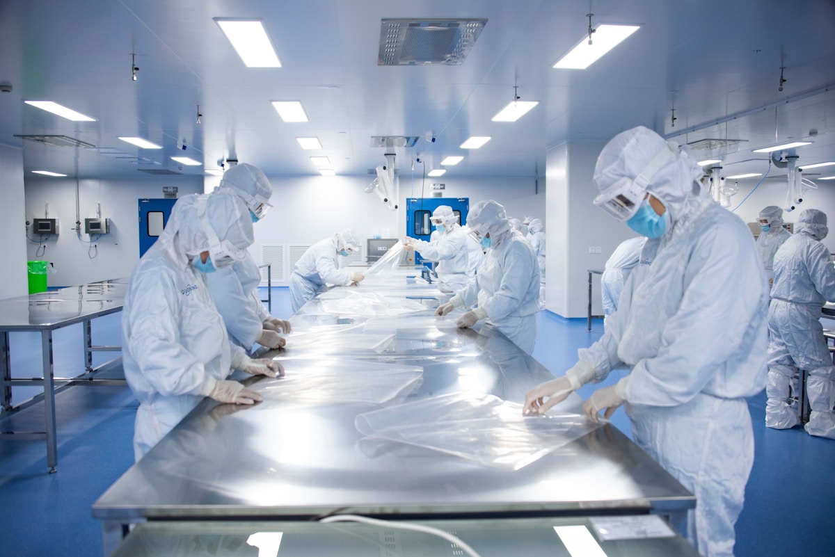
Proper cleanroom attire — including coveralls, hood, face mask, gloves, and booties — is designed to contain human-generated particles. However, research and facility audits consistently reveal that gowning gaps are the most common failure point. Wrists, necklines, and footwear represent the areas most frequently left exposed or improperly sealed, particularly during extended shifts when fatigue sets in and attention to detail decreases.
The consequences of these gaps are not theoretical. Studies have shown that inadequate gowning can increase particle counts by an order of magnitude compared to properly gowned personnel. This is why gowning audits and periodic retraining are not optional — they are fundamental components of any contamination control program that takes ISO compliance seriously.
Material and Equipment Decontamination Procedures
Materials entering a cleanroom — whether raw components, packaging, tools, or finished products — carry contamination from the outside environment. The standard approach involves a multi-stage decontamination process that typically includes outer packaging removal, surface cleaning with approved solvents, and passage through air showers or pass-through chambers before final entry into the controlled space.
Air showers use high-velocity, HEPA-filtered air to dislodge surface particles from personnel and materials. While they are a common entry method, their effectiveness depends on proper usage duration and direction. Studies indicate that air showers reduce surface contamination by 80 to 90 percent when operated for the recommended cycle time — typically between 20 and 60 seconds depending on velocity and user positioning.
Pass-through chambers serve a similar function for materials but operate on a different principle. These double-doored enclosures prevent simultaneous opening of both sides, maintaining the pressure barrier between clean and unclean zones. Materials enter through the outer door, the chamber is sealed, and the inner door opens only after the cycle completes. This simple mechanical interlock is one of the most reliable methods for preventing cross-contamination during material transfer.
Mobile Equipment and Maintenance Constraints
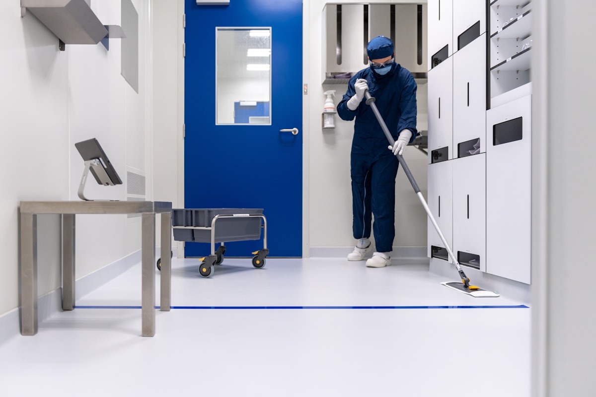
One of the most persistent operational challenges in cleanroom environments is the lack of approved mobile equipment. Maintenance teams frequently report difficulty finding mobile tool carts, computer workstations, and material transport tables that meet contamination control standards. The result is that workers often rely on existing approved carts rather than purpose-built solutions, which limits operational efficiency during servicing and repair activities.
This constraint has practical implications. When maintenance personnel cannot bring the right tools and documentation to a work location within the cleanroom, they may delay procedures, work around limitations, or inadvertently introduce non-compliant items. Facilities that proactively specify cleanroom-rated mobile equipment — with smooth, non-shedding surfaces, sealed casters, and integrated storage — see measurable improvements in both compliance rates and maintenance turnaround times.
- Surface materials: Mobile carts and equipment should use smooth, non-porous surfaces such as stainless steel or cleanroom-grade polymers that resist particle accumulation and allow effective cleaning.
- Caster selection: Sealed, cleanroom-rated casters prevent particle generation from wheel bearings and reduce the risk of contaminant pickup from floor surfaces.
- Design integration: Purpose-built mobile solutions that accommodate both tools and documentation reduce the need for multiple trips and minimize the number of items entering the controlled environment.
One-Way Flow and Workflow Design
Contamination control is fundamentally a matter of direction. One-way flow design ensures that personnel and materials move through the cleanroom in a single, predictable direction — from less clean to more clean zones — without crossing paths or reversing course. This principle applies to both personnel entry sequences and material transport routes.
The logic behind one-way flow is simple: when people and materials move in predictable patterns, contamination is carried away from critical areas rather than toward them. Reverse flow creates turbulence and cross-contamination risk that no amount of filtration can fully compensate for. Layout design should therefore prioritize unidirectional movement from the moment personnel don their gowns through the entire production or testing process.
Low-Shedding Work Practices
Beyond physical barriers and equipment, the daily behaviors of cleanroom personnel have a profound impact on contamination levels. Low-shedding work practices include moving deliberately rather than hurriedly, avoiding unnecessary gestures, minimizing conversation, and using approved cleaning materials that do not themselves generate particles. These practices may seem obvious, but they are consistently the most difficult to maintain over time.
The most effective facilities combine procedural training with environmental design that supports good habits. This includes providing adequate workspace to reduce crowding and rushed movements, using color-coded cleaning tools to prevent cross-contamination between zones, and establishing clear protocols for how materials are opened, handled, and disposed of within the controlled environment.
Ultimately, controlling contamination at its source is not about any single technology or procedure — it is about creating a system where every element, from gowning to material handling to mobile equipment selection, works together to minimize particle generation and prevent contamination from entering critical zones in the first place.
Modular vs. Stick-Built: How Construction Affects Cleanliness
The construction method chosen for a cleanroom is not merely a timeline or budget decision — it is the single most influential factor determining long-term particle control, validation success, and operational adaptability.
When facility managers and project leads in pharmaceuticals, biotech, and medical device manufacturing evaluate cleanroom construction approaches, the conversation often collapses into a simplistic cost comparison. This false binary obscures the deeper engineering reality: the way a cleanroom envelope is assembled directly dictates its ability to maintain classified air quality over years of operation. The decision between prefabricated modular panels and traditional field-erected construction carries implications far beyond the initial invoice, touching validation timelines, lifecycle contamination risk, and the facility’s ability to adapt to evolving regulatory or production demands.
How Construction Method Shapes Contamination Control
The fundamental difference between modular and stick-built cleanrooms lies in where and how the envelope joints are sealed. In modular systems, panel interfaces are engineered in a controlled factory environment with continuous gaskets pre-installed. These joints are designed to compress uniformly when the cam-lock mechanism is engaged, creating a repeatable, predictable seal. Every panel in a modular system arrives with the same joint specification, and the factory quality process ensures consistency across the entire run.
Stick-built construction, by contrast, assembles the envelope on-site from individual framing members, sheathing, and sealants. Each seam is cut, fitted, and sealed by field trades working in variable conditions. The sealant applied at these joints is subject to ambient temperature, humidity, surface preparation quality, and installer technique. Over time, these field-applied sealants shrink, crack, or degrade — creating micro-gaps that become the primary pathways for unfiltered air infiltration and particle accumulation.
This distinction is critical because joint leakage does not distribute evenly across a cleanroom envelope. It concentrates at panel interfaces and field-cut penetrations. Every electrical outlet, lighting fixture, or duct penetration in a stick-built room requires a hole cut in the field, followed by patching and resealing. Each of these locations represents a potential failure point. Modular systems address this by integrating service chases and pre-engineered cutouts during fabrication, eliminating the need for field modifications that compromise the envelope integrity.
Validation Timeline and Operational Readiness
The construction approach directly determines how quickly a cleanroom can move from installation to validated operation. Modular cleanrooms achieve operational readiness significantly faster because the panels are fabricated off-site while site preparation occurs in parallel. There is no waiting for sealants to cure, no drying time for field-applied finishes, and no sequential trade scheduling delays that compound in traditional construction.
For stick-built cleanrooms, the validation timeline extends well beyond the physical construction period. Field sealants require cure time before the envelope can be considered air-tight. HVAC balancing must account for the higher infiltration rates that result from less predictable joint performance, often requiring oversized equipment to compensate. The qualification process — installation qualification, operational qualification, and performance qualification — is frequently delayed by field corrections needed to address sealant failures, uneven surfaces, or unexpected air leakage paths discovered during testing.
In pharmaceutical and biotech environments, where speed-to-market directly impacts return on investment, this timeline differential is not a minor convenience — it is a strategic advantage. A cleanroom that reaches validated status weeks earlier generates revenue earlier and reduces the carrying costs associated with extended construction phases.
Long-Term Adaptability and Reconfiguration
Cleanroom requirements rarely remain static. Production scaling, process changes, and evolving regulatory expectations frequently necessitate layout modifications. The construction method chosen at the outset determines how disruptive and contamination-risky those changes will be.
Modular cleanroom panels can be disassembled, relocated, and reinstalled with minimal envelope compromise. Because the joint system relies on mechanical fastening and pre-installed gaskets rather than field-applied sealants, reconfiguration does not require cutting into the envelope or introducing new penetration points. Re-validation after relocation focuses on verifying the existing joint integrity rather than testing newly created seams.
Stick-built cleanrooms require demolition for any significant layout change. Every modification involves cutting through the existing envelope, creating new penetrations, and applying fresh sealants — each step introducing potential contamination events and requiring re-certification of the modified spaces. The more changes a facility makes over the cleanroom’s lifecycle, the more the initial construction method compounds in cost and risk.
Resolving the Decision Paralysis
The modular versus stick-built decision should be evaluated through a contamination-control lens first, with cost and timeline as secondary but important factors. Facility leaders who frame the question as “which option is cheaper to build” often arrive at stick-built solutions that carry hidden long-term costs in validation delays, HVAC oversizing, and reconfiguration disruption.
- Factory-sealed joints provide predictable, repeatable envelope performance that field construction cannot match — the gasket is installed under controlled conditions, not by an installer working in a partially finished space.
- Pre-engineered penetrations eliminate the dominant source of long-term leakage in stick-built rooms: the field-cut hole patched with sealant that cracks over time.
- Integrated service chases in modular systems keep electrical and mechanical routes contained within the panel structure, reducing the need for surface-mounted conduits that disrupt airflow patterns and collect particles.
- Reconfiguration without envelope compromise means that future production changes do not require contamination-risky demolition and resealing work.
The construction method is the foundation upon which every other cleanroom system — HVAC design, pressure cascades, filtration strategy, and validation protocol — is built. Choosing based solely on upfront cost ignores the compounding effect that envelope integrity has on classification maintenance, operational readiness, and lifecycle adaptability. The cleanroom that meets ISO requirements at commissioning is only the first milestone; the one that maintains those requirements through years of operation is the true measure of a well-engineered construction approach.
| Parameter | Modular Cleanroom | Stick-Built Cleanroom | Design Implication |
|---|---|---|---|
| Construction Method | Factory-fabricated sandwich panels (GRP/FRP with PIR, rockwool, or honeycomb cores) assembled on-site via cam-lock tongue-and-groove joints | Field-erected stud framing with drywall, tile, or sheet metal cladding, sealed with mastic and tape | Modular joints are factory-gasketed; stick-built seams rely on field-applied sealants that degrade and shed particles over time |
| Panel Joint Air Leakage Target | 1–2% system leakage at design pressure when cam-lock joints with continuous gaskets are specified | Typically 3–5% leakage due to field-cut penetrations, irregular seams, and sealant shrinkage | Joint leakage concentrates at panel interfaces — spec the joint system, not just the skin material |
| Surface Cleanability & Material | Smooth GRP/FRP gelcoat skins resist moisture, UV, and repeated chemical washdown; no porous joints | Painted drywall or exposed metal tiles harbor microbes at seams; gelcoat-equivalent finishes are rare | Non-shedding, washable envelopes prevent microbial harborage and support ISO 14644-2 monitoring protocols |
| Thermal Bridging & Condensation Risk | Insulated sandwich cores (PIR/PU/XPS) eliminate thermal bridges; ≤2°C delta maintained across envelope | Metal studs and framing create thermal bridges; condensation risk in washdown zones and cold rooms | Condensation enables microbial growth — RaxPanel-type insulated envelopes seal the cleanroom against this failure mode |
| Penetrations for Services (Lights, Ducts, Outlets) | Factory-integrated flush service chases and pre-engineered cutouts; zero field-cut penetrations | Field-cut holes for every penetration; patched with sealant that cracks and sheds | Every field-cut penetration is a leakage and particle-shedding risk — pre-fab integration is the compliance advantage |
| Pressure Cascade Maintenance (0.02–0.05 in w.g. per stage) | Airtight envelope preserves cascade; HVAC sizing is predictable and optimized | Leaky seams force HVAC oversizing by 15–25% to compensate for uncontrolled infiltration | Envelope airtightness directly sizes HVAC capital cost — the panel-to-HVAC link is the lifecycle cost lever |
| Reconfiguration & Relocation Flexibility | Disassembled and reinstalled; ISO class re-validated in days, not months | Demolition required for any layout change; re-validation involves full rebuild and re-certification | Modular systems support GMP change-control without envelope compromise; stick-built changes introduce contamination events |
| Commissioning & ISO Validation Timeline | 50–70% faster operational readiness; IQ/OQ/PQ completed in weeks | Extended curing, sealing, and balancing; validation delayed by field corrections | Faster commissioning reduces cleanroom cost per square foot at every ISO class tier |
Conclusion
Clean room design isn’t about stacking filters and hoping for the best. It’s a system where ISO class, air change rates, pressure differentials, and construction method all lock together. Get the pressure gradient wrong and your HEPA filters are just expensive dust catchers. Modular panels give you tighter tolerances faster. Stick-built construction can work but demands more validation time and trades coordination on site.
- Verify your ISO class maps to actual air change requirements before finalizing HVAC specs.
- Confirm pressure differentials account for door opening frequencies in your workflow.
- Request panel samples and cross-section documentation from your supplier, and bring your preliminary specs to our engineering team — we’ll flag design gaps before you lock in contractors.
Frequently Asked Questions
What is a sterile cleanroom?
A sterile cleanroom is a controlled environment designed to prevent microbial contamination in addition to particulate control, typically required for aseptic pharmaceutical processing and injectable drug manufacturing. It combines ISO class air cleanliness with surface decontamination protocols, UV or vaporized hydrogen peroxide (VHP) room-level disinfection, and strict personnel gowning procedures. Sterile cleanrooms often target ISO 5 or better in critical operation zones while maintaining higher classifications in anterooms and support areas.
What is a softwall cleanroom?
A softwall cleanroom uses flexible curtains or plastic strip dividers instead of rigid walls to contain controlled airflow. It relies on high-velocity vertical laminar airflow from HEPA-filtered ceiling units to maintain cleanliness rather than a sealed envelope. Softwall units are lower-cost and faster to install but achieve only ISO 7 to ISO 8 classification. They are unsuitable where pressure cascades or washdown sanitation are required.
Why is 10 Pa the minimum pressure differential?
A 10 Pa (0.04 in w.g.) minimum differential ensures that airflow moves from cleaner to less-clean zones even during door openings or HVAC transients. Below this threshold, measurement uncertainty and minor pressure fluctuations can reverse airflow direction, allowing contaminated air to migrate into critical spaces. ISO 14644-3 and GMP guidelines cite 10 Pa as the practical design floor for reliable containment.
How do panel joints affect cleanroom air leakage?
Panel joints are the weakest points in a cleanroom envelope and the primary path for unfiltered air infiltration. Cam-lock tongue-and-groove joints with continuous gaskets can achieve the 1–2% total envelope leakage target specified by ISO 14644-3. Poorly sealed joints allow pressure cascade failure and localized particle accumulation. Joint leakage should be tested at 50 Pa differential pressure and verified above that range for high-class cleanrooms.
Can a positive pressure cleanroom be converted to negative pressure?
Conversion is possible but requires re-engineering the HVAC supply and exhaust balance, re-verifying pressure cascades, and often modifying the envelope penetrations. Negative pressure cleanrooms require exhaust HEPA filtration to prevent contaminated air release, which adds cost and complexity not present in positive-pressure designs. RaxPanel engineers recommend designing dual-mode HVAC capacity into the initial specification when future mode conversion is anticipated, avoiding costly retrofits.
What is the difference between GRP and FRP cleanroom panels?
GRP and FRP are interchangeable acronyms for the same material: glass-reinforced plastic, also called fiberglass-reinforced plastic. Both terms describe a composite panel with a fiberglass reinforcement matrix, typically coated with a gelcoat surface that provides a smooth, chemical-resistant, and cleanable finish. When comparing GRP/FRP sandwich panels for cleanroom walls, focus on core material, gelcoat quality, and joint design rather than the acronym used.
What drives cleanroom construction costs beyond the panel quote?
HVAC and filtration typically represent 40–60% of total cleanroom capital cost, making envelope airtightness and thermal performance critical budget levers. A well-insulated, low-leakage panel system reduces the required airflow volume and allows smaller HEPA fan-filter units, directly lowering both equipment cost and lifetime energy consumption. Additional cost drivers include cleanroom-rated lighting, pass boxes, anteroom sequencing, and validation testing per ISO 14644-2.