
Cold room construction is fundamentally different from standard warehousing. You are not simply erecting walls; you are assembling a sealed vessel designed to resist constant thermodynamic pressure. If you treat the foundation or panel joints like a standard drywall job, you will face immediate condensation issues and structural failure. To maintain the extreme temperature ranges required for deep-freeze applications—often dipping to -40°C—the insulation envelope must be airtight, with zero tolerance for thermal bridges.
We walk through the precise assembly sequence required to achieve that seal. This guide covers site preparation, panel interlocking techniques, and the final positioning of refrigeration units. Follow these steps to ensure your installation meets fire ratings and avoids the energy penalties that plague poorly sealed storage facilities.
What to Check Before You Start Assembling
Before any panel goes up, verify four physical prerequisites: foundation flatness, inventory completeness, utility access, and internal clearance dimensions.
Site Surface Flatness and Load-Bearing Verification
Modular cold rooms rely on precise panel alignment. When your foundation is uneven, every subsequent component compounds that error—gaskets lose compression, joints develop micro-gaps, and thermal bridges emerge at the weakest seams.
A standard concrete slab for commercial cold storage must meet both flatness tolerances and structural load capacity. Use a laser level across the entire footprint before placing the first panel. Any deviation exceeding ±3mm over a 2-meter span requires grinding or self-leveling compound correction. Don’t assume the slab is ready just because it’s poured.
Load-bearing verification isn’t about how much weight the floor holds—it’s about whether it holds evenly. Point loads from palletized product, forklift traffic zones, and concentrated equipment weight create stress fractures in the panel interlocks over time. Our engineering team reviews foundation plans against your planned storage density before shipping begins.
- Flatness Check: Laser-level the entire installation area; correct deviations before panel delivery
- Load Rating: Confirm slab PSI meets maximum point-load requirements for your planned racking and equipment
- Damp Proofing: Verify vapor barrier integrity beneath the slab to prevent moisture migration through the panel base track
Complete Panel Kit and Hardware Inventory Audit
A cold room project stalls fastest when you discover missing hardware mid-installation. One incorrect bolt type or absent sealing tape roll can halt an entire crew for days while waiting for replacement shipments.
Cross-reference every component against the packing list before unloading. Count panel sets, verify hinge assemblies, confirm latch mechanisms, and inspect gasket continuity. Document any transport damage immediately with photos and notify the supplier before signing the delivery receipt.
We’ve encountered projects where panels arrived intact but fastener kits were incomplete—specifically the concealed mechanical lock bolts that join wall panels together. Always request a hardware allocation sheet matching your room’s perimeter, door openings, and ceiling span before the container arrives at site.
- Panel Count: Verify wall, roof, and floor panel quantities against the engineered layout drawing
- Hardware Batch Match: Ensure all fasteners, brackets, and seals share the same production batch for consistency
- Damage Inspection: Photograph and log any dents, scratches, or crushed corner protection before acceptance
Electrical Supply and Drainage Point Readiness
Utility connections must be accessible before the room is sealed. Once panels are locked into place and the thermal envelope is complete, rerouting power cables or drainage lines becomes invasive, expensive, and risky to insulation integrity.
Confirm three electrical parameters upfront: voltage rating matches the compressor specification, amperage capacity supports peak startup surge, and conduit routing avoids penetrating the insulated panel core. Drilling through foam insulation for field-modified electrical runs creates thermal bridges and compromises the vapor seal.
Drainage planning follows the same logic. Condensate lines from the evaporator and door heaters need gravity-fed slopes toward the nearest drain or pump station. If you wait until after installation to locate the drain, you’ll likely route lines externally—which looks unprofessional, collects debris, and freezes in cold environments.
- Voltage Confirmation: Match supply voltage and phase to the refrigeration unit nameplate before energizing
- Conduit Path: Pre-drill or pre-route electrical access through structural framing, never through foam cores
- Drain Slope: Verify condensate line gradient toward the collection point before sealing the room
Never penetrate insulated panel facings or cores for last-minute electrical modifications. Every penetration creates a future condensation point and voids fire-rated certifications.
Interior Dimension Accuracy and Clearance Confirmation
Cold room manufacturers engineer panels to tight tolerances, but site conditions rarely match drawings exactly. Verify interior dimensions against your stored product dimensions, equipment footprints, and door clearance requirements before committing to the final panel cut.
Measure the rough opening for walk-through doors at three heights: top, middle, and bottom. Door frames require consistent clearance around the gasket compression zone. If the opening varies by more than 5mm between measurements, investigate the cause before proceeding—usually a foundation settlement issue or framing out-of-square condition.
Clearance also applies to internal equipment. Pallet racking, conveyor entrances, and evaporator return-air pathways need unobstructed space. A room that fits your product today may not accommodate tomorrow’s expansion plans. Our design engineers recommend adding 50-100mm of operational clearance beyond minimum required dimensions for service access and airflow management.
- Door Rough Openings: Measure width and height at multiple points; correct any out-of-square conditions
- Equipment Clearance: Confirm evaporator placement, racking spacing, and aisle widths against panel layout
- Expansion Buffer: Leave service access space around all mechanical penetrations for future maintenance
| Pre-Assembly Check | Technical Specification | Acceptance Threshold | Failure Consequence | Engineering Verification |
|---|---|---|---|---|
| Operating Temperature vs. Panel Thickness | Core thermal conductivity specific to target storage temperature | ≥100mm PU core for -18°C; ≥150mm for -30°C; k-value validated at sub-zero, not ambient | Interstitial condensation, vapor drive, and excessive compressor cycling | Cross-reference independent lab thermal conductivity reports against operating temperature profiles |
| Core Material Selection (PU vs. XPS) | Core material moisture absorption rate and thermal efficiency | PU k-value ≤0.022 W/m·K; XPS water absorption <1% for high-humidity zones | Insulation degradation, loss of R-value, and structural failure in moist environments | Match closed-cell structure integrity to zone-specific humidity and load requirements |
| Fire Rating Documentation | Panel core and facing fire reaction classification | Class A or B1 certification via accredited laboratory test reports per batch | Building code violations, insurance invalidation, and mandatory facility retrofitting | Verify physical test certificates match batch production and local building codes |
| Door Seal & Thermal Bridge Prevention | Door gasket compression ratio and thermal bridge integrity | Gasket compression ≥30%; zero visible light penetration (<500 lux) at 2mm hinge tolerance | Frost accumulation, air infiltration, and 15-25% increase in energy consumption | Perform dry-fit seal test prior to final locking to ensure continuous thermal break |
| Joint Interlock & Sealing Continuity | Panel joint geometry engagement and seal continuity | Male/female groove engagement ≥80%; continuous application of foil sealing tape | Structural misalignment, thermal envelope leakage, and compromised panel integrity | Inspect groove deformation post-transport and verify interlock depth before lifting |
| Facing Material Hygiene & Durability | Facing surface hygiene rating and impact resistance | Non-porous GRP gelcoat, Stainless Steel, or Aluminum; ISO 21930 compliant hygiene rating | Microbial growth, surface corrosion, and failure to pass FDA/USDA hygiene audits | Confirm material data sheets support specific chemical cleaning agents and impact loads |

The Build Path: From Base to Final Check
Cold room failures come from broken sequence logic, not missing hardware. Every handoff needs a measured quality gate before the next phase begins.
Procurement teams often underestimate how tightly coupled a modular insulated panel system is. When builders treat the base, envelope, refrigeration, and sealing as independent tasks, thermal bridges accumulate at intersection points and final temperature stabilization repeatedly fails. The build path is a closed dependency chain. Each upstream phase must meet a strict tolerance threshold before the downstream phase can safely lock into place. Decoupling these stages creates compounding rework that no final inspection can fully correct.
The Dependency Chain Logic
A cold room behaves like a pressurized vessel. Individual wall plates or roof decks do not create the seal; the join sequence does. The floor datum establishes the horizontal reference for every vertical panel. The vertical grid defines the roof module layout and drainage slope. The roof closure protects the insulation core before mechanical cooling introduces internal thermal stress. If any node in this chain shifts out of tolerance, the entire envelope loses systemic integrity.
- Base-to-Envelope Handoff: The structural platform must hold a flatness tolerance of ≤3 mm across a 2-meter straightedge. Deviation here forces panel adapters to absorb stress, which eventually cracks gelcoat finishes and compromises joint compression.
- Envelope-to-Roof Handoff: Wall panel plumb and seam alignment lock the roof module geometry. Misaligned vertical joints create uneven load distribution, which warps lightweight composite decking over time.
- Roof-to-Mechanical Handoff: The cooled envelope must be fully enclosed and sealed before evaporator installation. Introducing active cooling to an open grid causes condensation inside unsealed cores before the thermal barrier is complete.
- Mechanical-to-Seal Handoff: Refrigeration placement dictates internal airflow paths. Door gasket compression and wall penetrations must align with the calculated air exchange volume to prevent thermal bridging at high-moisture zones.
- Seal-to-Commission Handoff: Final temperature stabilization requires ±1 °C tolerance from the target setpoint. Only a fully bonded envelope with zero compromised joints can reach recovery targets within the design window.
Insulation Thresholds That Drive the Build Sequence
Material selection directly controls how fast each phase must be completed and what verification metrics apply. The two dominant foam cores for freezing storage differ in thermal resistance, which changes the required panel thickness and the allowable exposure window during assembly.
- Polyurethane Foam (PU): Thermal conductivity ranges from 0.022 to 0.024 W/(m·K). A W/(m·K) value measures how easily heat moves through a material; lower numbers mean better insulation. For freezing storage at -18 °C to -25 °C, PU cores typically require 150 mm to 200 mm panel thickness to meet commercial load-bearing and thermal standards.
- Extruded Polystyrene Foam (XPS): Thermal conductivity ranges from 0.028 to 0.032 W/(m·K). XPS offers higher compressive strength but slightly lower thermal resistance, which often pushes required panel thickness toward the upper end of the 150–200 mm range for deep-freeze applications.
- Open-Cell Exposure Window: Foam cores lose performance rapidly when exposed to moisture during assembly. PU and XPS panels must be joined, sealed, and mechanically commissioned within the same work shift whenever possible. Delaying the roof-to-seal handoff allows ambient humidity to degrade the core before the envelope closes.
These thermal properties are not theoretical. They dictate the pace of field assembly. A panel system that claims superior strength but slower curing or longer seam-setting times changes the entire labor schedule. Builders who ignore conductivity thresholds often rush the sealing phase, which creates hidden thermal bridges that trip up final commissioning.
Where Sequencing Breaks the System
Installing refrigeration equipment before the full panel grid is locked and sealed introduces a moisture trap. Warm, humid air contacts cold foam cells, which accelerates core degradation and voids thermal performance guarantees.
The most expensive rework loops come from three predictable sequencing errors. First, measuring only the outer room dimensions instead of verifying the internal grid tolerance causes panel gaps that exceed gasket compression limits. Second, skipping joint seal verification between wall and roof modules leaves micro-leaks that condensation amplifies during compressor cycling. Third, placing cooling units without mapping the return-air pathway forces the system to fight its own thermal dead zones, which drives energy consumption far above design estimates.
A disciplined build path treats each phase as a documented checkpoint, not a finishing step. Tolerances are recorded, seal integrity is confirmed before mechanical activation, and material exposure windows are respected. This approach converts a complex modular assembly into a predictable engineering sequence, where the final temperature test becomes a confirmation of proper construction rather than a surprise audit.
Lay a Flat, Sturdy Floor to Prevent Warping
A cold room floor is the structural reference plane that keeps insulated panels aligned. Without a level, stable base, thermal cycling and load shifts force panels out of plane, breaking seals and accelerating warping.
Cold room panels are rigid composite structures engineered to lock together in precise alignment. When installed over an uneven or unstable subfloor, the panels are physically forced to compensate for height differences during assembly. In freezing storage environments, repeated temperature swings cause materials to expand and contract.
If the underlying slab settles unevenly or contains high spots, the panel joints experience continuous shear stress. Over time, this leads to visible bowing, compromised gasket compression, and localized thermal bridging where warm air infiltrates the envelope.
Why Substrate Irregularity Causes Panel Warping
Think of the floor system like a book resting on a table. If the table surface dips or tilts, the book cover bends to match it. Sandwich panels behave similarly. Once bonded and sealed, they lose the ability to flex without stressing the facing sheets and core interface. An unlevel foundation transfers that distortion upward into the wall and roof assemblies, making every subsequent seam harder to close properly.
Site preparation oversights are rarely dramatic on day one. A minor dip that seems acceptable during dry fitting becomes a leverage point once forklift traffic, racking loads, or freeze-thaw cycles engage the structure. Differential settling creates concentrated bending moments at panel edges, which eventually manifests as warping, visible seam gaps, and reduced insulation performance.
Establishing Full-Length Contact Without Point Loading
Professional installations prioritize uniform contact between the panel core and the prepared surface. A properly applied leveling compound fills voids and creates a consistent bearing plane, eliminating concentrated pressure points. When a panel rests on isolated high spots, the unsupported sections become vulnerable to flexing under equipment movement or stored goods.
Ensuring the substrate provides continuous engagement protects the adhesive bond line, which relies on full surface contact to maintain dimensional stability. This practice also prevents hidden stress accumulation that would otherwise degrade the panel’s structural rigidity over months of operation.
- Verify full-floor levelness: Run checks across the entire room footprint before placing any panels, not just at corner reference points.
- Confirm utility and drainage positioning: Route electrical conduits and floor drains before final surface finishing to avoid cutting into a completed base later.
- Inspect vapor barrier continuity: Ensure moisture protection remains uninterrupted beneath the insulation layer, with all seams properly sealed.
- Validate load-bearing capacity: The prepared surface must resist deflection under anticipated forklift routes and static storage weight.
Moisture Control and Underground Thermal Isolation
Ground-level cold rooms require careful management of moisture migration and heat transfer from the soil below. Uncontrolled dampness weakens adhesives and promotes facing delamination, especially in fiber-reinforced or polymer skin systems exposed to frequent washdown cycles. A continuous vapor retarder laid beneath the thermal break layer blocks capillary rise and preserves core integrity.
Thermal isolation is equally critical. Without a dedicated break between the refrigerated envelope and the structural concrete slab, conductive cold loss triggers uneven contraction at panel interfaces. This mismatch accelerates joint fatigue and can warp panels that were originally installed within tolerance.
Skipping slab moisture verification before panel installation often leads to delayed failures. Installing panels over a recently poured or inadequately cured concrete base traps residual water, which later migrates into foam cores or compromises faced bonding. Always confirm the substrate is fully dry and dimensionally stable before proceeding.
Always run a straightedge check across multiple directions before committing to panel placement. Even minor dips or rises outside tolerance will transfer directly into the wall and roof assemblies, making subsequent sealing and alignment significantly harder.
| Layer/Component | Specification Requirement | Tolerance/Standard | Purpose | Warping Prevention Mechanism |
|---|---|---|---|---|
| Base Subfloor | Reinforced concrete slab, minimum C25 grade | Flatness ≤3 mm over 2 m span | Provides uniform structural load distribution | Prevents differential settling that stresses panel joints |
| Moisture Barrier | Continuous polyethylene vapor retarder, min 0.2 mm thickness | Joint overlap ≥150 mm; all seams heat-sealed | Blocks ground moisture migration into the panel core | Stops foam core absorption and facing delamination caused by humidity |
| Leveling Compound | Self-leveling epoxy or polymer-modified cementitious screed | Surface deviation <1 mm per 1 m straightedge | Creates a smooth, rigid substrate for panel adhesion | Ensures full-length panel contact and eliminates concentrated point loads |
| Thermal Break Layer | XPS or PET foam core sandwich panel, 50–100 mm thick | Thermal conductivity λ ≤0.030 W/m·K; panel thickness within ±3 mm | Isolates cold transfer from the structural slab to the cold room envelope | Prevents thermal contraction warping at panel interfaces during freeze-thaw cycles |
| Surface Finish | GRP/FRP or stainless steel facing sheet, smooth bond | Surface flatness ≤2 mm; impact and chemical-washdown rated for forklift traffic | Withstands hygienic washdown protocols and mechanical stress | Maintains dimensional stability under repeated cleaning and temperature fluctuations |
How to Lock Wall Panels and Seal Every Seam
Achieving an airtight thermal envelope requires a dual-lock strategy: mechanically fastening the panels while simultaneously creating a vapor-tight seal. If the structural joint is tight but the sealant is broken, cold air will leak, energy costs will spike, and condensation will inevitably destroy the insulation.
What Is Panel Engagement Systems?
In modern cold room construction, two primary connection methods dominate the industry: the cam-lock system and the tongue-and-groove joint. For high-performance freezing and storage applications, the cam-lock mechanism is generally preferred due to its superior tensile strength and ease of assembly. This system utilizes zinc-coated steel hooks embedded within the panel core, typically spaced at intervals of 300 mm, to pull adjacent panels together with significant force.
When installing these mechanisms, precision is critical. The locking action draws the male and female edges together until the foam cores compress slightly, ensuring a structural bond. However, installers must resist the urge to over-tighten. Excessive force with a hex key can crush the rigid insulation core—whether it is Polyurethane (PU), XPS, or PET—creating permanent gaps that compromise thermal resistance.
Always engage cam-locks in a sequential “zig-zag” pattern rather than tightening one fully before moving to the next. This distributes the pulling force evenly across the entire panel face, preventing bowing and ensuring the female groove remains perfectly aligned to receive the sealant.
The Sequential Sealing Protocol
Mechanical locking alone is never enough. The sealant acts as the primary vapor barrier, preventing humid external air from penetrating the envelope and condensing inside the wall cavity. The industry standard “pre-seal” method is the only reliable way to guarantee a continuous barrier.
This protocol dictates that a continuous bead of cold room mastic or silicone must be applied into the female groove of the panel before the male edge is inserted.
This ensures that as the panels slide together, the sealant is forced into every microscopic crevice of the joint without being scraped away or left exposed to the elements. Skipping this step and attempting to inject sealant from the exterior after installation often results in voids behind the joint, creating a hidden pathway for heat transfer.
📋 Verification Checklist
- Step 1: Inspect the female groove for debris or foam shavings; clean thoroughly.
- Step 2: Apply a steady, uninterrupted bead of mastic along the full length of the groove.
- Step 3: Slide the male edge into the groove and engage the cam-locks until the joint is flush.
- Step 4: Wipe away excess squeeze-out immediately to prevent curing on the surface, but do not dig into the joint.
- Step 5: Visually confirm no “daylight” is visible through the seam from the interior.
Preventing Thermal Bridge Disasters
A thermal bridge occurs when a conductive material bypasses the insulation layer, creating a cold spot. In panel systems, this most commonly happens at wall-to-ceiling or wall-to-floor transitions if the connection details are neglected. When the interior surface temperature drops below the dew point, moisture condenses. Over time, this trapped water degrades the adhesive bonds in the sandwich panel and fosters mold growth.
To mitigate this risk, installers must ensure that the sealant bead continues uninterrupted around all corners. Specialized corner flashings or “fillet” seals made of compatible silicone should be applied to transition from the vertical wall to the horizontal floor or ceiling. For applications requiring strict hygiene standards, such as food processing facilities, these corners must be coved (rounded) to allow for cleaning and prevent bacterial buildup in the joint gap.
Never assume the factory-applied gasket is sufficient. While many panels come with pre-installed rubber seals, thermal expansion and contraction can cause these to pull away from the wall. A wet-applied chemical sealant (mastic) is non-negotiable for long-term thermal integrity.
Secure the Roof Panels and Seal Joints Against Warm Air
Material selection at this point sets the thermal efficiency, fire rating, and weight of the finished assembly. Balance R-value requirements against span capability and code-mandated fire performance.
The Critical Role of the Roof Envelope
Since warm air rises, the roof is the primary point of energy loss in a cold storage facility. Improperly sealed roof joints can increase refrigeration running time and significantly compromise thermal efficiency.
In any refrigerated environment, the ceiling acts as the primary shield against heat gain. Because warm air naturally rises and carries more moisture than cold air, the roof panels face the most severe pressure differentials. If the roof joints are not perfectly sealed, this warm, moist air infiltrates the cold space.
Upon contact with the cold panel surfaces, the moisture condenses rapidly, leading to water dripping onto stored goods and creating a breeding ground for mold and mildew. Using high-performance insulation cores like Polyurethane (PU) or Polyisocyanurate (PIR) is essential, but even the best cores fail if the perimeter joints allow thermal leakage.
Mechanical Securing: Cam Locks and Fasteners
The first step in securing the roof is ensuring the mechanical connections are tight and aligned. Most modern modular cold rooms use cam locks to draw panels together. A common installation error is over-tightening these locks. Over-tightening can strip the locking mechanism or crush the insulation core at the joint edge, creating a gap rather than sealing it. Installers should turn the lock until firm resistance is felt—usually a quarter-turn past engagement—without forcing it.
- Alignment Check: Before tightening, ensure the tongue-and-groove profiles of adjacent roof panels are perfectly flush. Misalignment forces the foam core to compress unevenly, leaving permanent voids.
- Support Structure: For wider spans, ensure the underlying support structure (steel joists or suspension systems) is level. An uneven substructure causes the panels to bow, breaking the seal at the joints.
Sealing Joints: Blocking Warm Air and Moisture
Mechanical locks hold the panels together, but they are not airtight by themselves. To effectively seal against warm air, a continuous gasket or sealant is required. In premium panel systems, a pre-installed rubber gasket sits within the tongue-and-groove joint. When the cam lock is engaged, this gasket compresses to form a vapor-tight seal. For systems relying on field-applied sealants, apply a continuous bead of high-quality, cold-room-grade silicone or polyurethane sealant along the joint edge before assembly.
Special attention must be paid to the connection between the roof panels and the wall panels (the ceiling-wall corner). This transition point is highly susceptible to thermal bridging. A “fillet” seal—often created using a specialized liquid sealant or a pre-molded foam corner piece—ensures that the curvature of the joint remains insulated and airtight, preventing warm air from sneaking through the crevice.
Do not assume that a tight-looking joint is sealed. Thermal bridges at joints are imperfections that extract heat continuously. In commercial setups, an unsealed joint run can lead to significant energy loss and visible condensation within 6 to 12 months. This moisture intrusion degrades the insulation value of the panel over time and can cause delamination of the facings.
Verification Protocol: The Final Acceptance Test
Before considering the installation complete, a verification process is mandatory. A simple visual inspection is often insufficient. One effective method is the “smoke test,” where a smoke pencil is held near the joints while the room is pressurized slightly. If the smoke is drawn into or blown out of the joint, the seal is compromised.
📋 Installation Quality Checklist
- Step 1: Visually inspect all roof joints for uniformity. Ensure there are no visible gaps where light can penetrate through the core.
- Step 2: Check cam locks are not stripped or protruding, which indicates poor alignment or over-tightening.
- Step 3: Verify the application of sealant or gaskets at the ceiling-wall intersection.
- Step 4: Conduct a smoke test or pressurization test to confirm the room is airtight before the cooling unit is turned on.
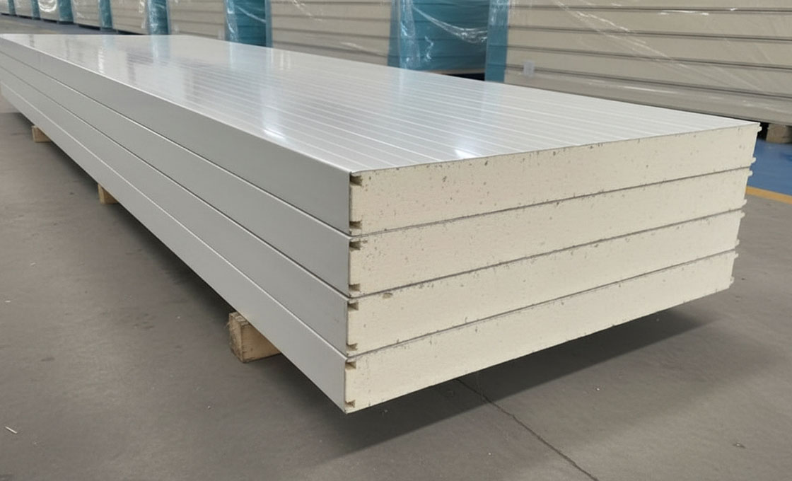
Position the Cooling Unit with Room for Airflow and Drainage
Positioning the cooling unit correctly determines whether a cold room maintains even temperatures or develops destructive hot and cold zones. Proper airflow clearance and drainage geometry protect inventory value and keep energy consumption predictable.
The Physics of Evaporator Placement
A cold room cooling system works by moving heat, not creating cold. The evaporator coil inside the room absorbs warmth from the air, while the condenser unit outside releases that heat into the atmosphere. If the evaporator fan pushes cold air into a wall, a pallet stack, or a narrow corner, the air cannot circulate back to the unit. The result is a temperature gradient where stored goods freeze in one area and spoil in another.
Think of the evaporator like a lung: it needs both an open intake and a clear exhaust path to breathe properly. In a standard modular build, the evaporator should be mounted high on an interior wall, ideally opposite the loading door. This placement forces the cold air to travel the full length of the room before returning to the intake, creating a complete circulation loop rather than short-circuiting near the door.
Clearance Requirements for Unblocked Airflow
Insulated sandwich panels, regardless of whether they use PU foam, XPS, PET, PMI, or honeycomb cores, must never be placed in the direct throw path of the evaporator fan. Obstructed discharge areas force the compressor to run longer cycles, spike electricity bills, and increase the risk of coil icing.
- Discharge Clearance: Maintain at least 600mm to 900mm of open space in front of the fan grille. This gives the air stream enough room to develop before hitting racking or stored product.
- Return Air Intake: Keep the rear and sides of the unit free from panel joints, wall corners, or stacked goods. Restricted intakes starve the coil of warm air, causing inefficient heat exchange.
- Condenser Ambient Access: The outdoor condenser needs unobstructed exposure to fresh air. Clamping it against a wall or tucking it into a ventilation shaft traps rejected heat and reduces cooling capacity by up to 30% in extreme cases.
Drainage Geometry and Condensate Management
Every time the evaporator coil operates, moisture from the air condenses on its surface. This water must flow away cleanly through a dedicated drain line connected to the pan. If the drain path is flat, uphill, or too long without a proper slope, water sits in the pan, refreezes into an ice block, and eventually chokes the airflow completely.
In modular cold room construction, the drain line usually routes along the base of the insulated wall or through pre-cut channels in the panel joints. The slope should remain continuous and downward toward the building drainage point. Even a slight reverse pitch creates a water trap that leads to biological growth, unpleasant odors, and potential short-circuit risks near the electrical control box.
Mounting the evaporator directly above the loading doorway is a common mistake. Every door opening floods the unit with warm, humid air, triggering excessive defrost cycles and wasting energy. Always place the cooling unit on an interior wall, away from the door swing and high-traffic zones.
Sealing Joints Around the Cooling Unit
Where the cooling unit housing meets the insulated wall panels, thermal bridges form if gaps are left uncovered. Warm exterior air leaking into the cold room cools instantly against the panel surfaces, creating condensation inside the joint. Over time, moisture penetrates the foam core or honeycomb structure, degrading insulation performance and increasing load on the refrigeration system.
Use closed-cell sealant or compatible gasket tape around all mounting brackets, drain line penetrations, and electrical conduit entries. Do not rely on expanding foam alone, as it can crack under vibration and create uneven thermal paths. A tight, flexible seal keeps conditioned air inside the envelope and protects the structural integrity of the panel cores.
Before sealing the final panels around the cooling unit, run a temporary power test. Verify that the fan throws air straight down or across the room, check that the drain pan empties without backing up, and confirm the defrost cycle does not drip onto nearby panel seams. Catching these issues early saves costly teardown later.
Fit the Door and Ensure the Gasket Seals Tight
The access door is the single most vulnerable thermal weak point in a cold room envelope. Unlike static insulated walls, every time the door opens, warm and humid air rushes inward. Proper hinge alignment, gasket compression, and perimeter sealing prevent rapid temperature fluctuation and avoid the 10–15% energy cost spike caused by compromised door seals.
Align the Hinges and Check the Swing
Before sealing the perimeter, mount the door onto the hinges and verify full swing clearance. A misaligned door drags against the frame, warping the gasket and leaving gaps where cold air escapes. Lift and lower the door slowly to ensure it moves smoothly without binding, then confirm the latch engages firmly without requiring excessive force.
- Clearance Check: Ensure there is equal spacing around the entire door perimeter. Uneven gaps indicate frame shift or panel misalignment that must be corrected before sealing.
- Hinge Stress Test: Open the door to 90 degrees and release it briefly. It should hold its position or close slowly under its own weight, depending on the design specification.
- Latch Engagement: The strike plate must align precisely with the latch bolt. Forcing the handle indicates structural misalignment that will degrade the gasket over time.
Verify Gasket Compression and Perimeter Sealing
The rubber or thermoplastic gasket acts as a flexible thermal break between the metal frame and the insulated door skin. Its effectiveness depends entirely on uniform compression. If the gasket is too loose, warm air infiltrates; if it is crushed unevenly, moisture bridges form and frost accumulates along the seam.
To verify proper compression, perform the paper test: close the door on a standard sheet of paper and try to pull it out. You should feel consistent resistance across all edges. If the paper slides out freely, the gasket is not compressing enough at that point and the frame alignment must be adjusted.
Think of the gasket like a zipper on a waterproof jacket. If even one tooth is out of alignment, the entire barrier fails. Always inspect the gasket channel for debris or adhesive residue before final closure.
- Perimeter Seal Continuity: Run a finger along the gasket contact line while the door is closed. There should be no hard spots, exposed frame metal, or irregular bumps.
- Cold Bridge Prevention: Ensure the gasket completely separates the inner and outer door skins. Any direct metal-to-metal contact creates a conductive path that accelerates frost buildup.
- Moisture Management: After compression verification, inspect the threshold area for potential water pooling. A properly sealed bottom gasket should direct condensation away from the floor joint.
Confirm Magnetic Seals and Automatic Closers
High-performance cold room doors often integrate magnetic gaskets and automatic door closers to maintain temperature stability without relying on human compliance. Magnetic seals provide an even tighter closure than standard compression rubbers, eliminating micro-gaps around the frame corners where frost typically initiates.
Test the automatic closer by opening the door fully and releasing it. The mechanism should pull the door shut smoothly and engage the seal completely within the specified closure time. If the door slams or stops short, adjust the hydraulic or pneumatic tension to prevent gasket damage and thermal loss.
Never skip the perimeter seal check after installing heavy-duty sliding or hinged commercial doors. Frame settlement during transport can shift the door aperture by millimeters, breaking the gasket seal even if the hinges appear correctly aligned.
Final Checks: Testing the Temperature, Alarms, and Performance
Final acceptance requires a controlled ramp-down test, independent alarm verification, and a signed handover document that clearly separates manufacturing defects from installation errors before releasing final payment.
Validating Temperature Recovery and Insulation Integrity
Hitting the target setpoint is not enough. A properly sealed cold room must demonstrate stable recovery after simulated door openings and maintain uniform thermal distribution across corners, ceilings, and floor joints. Insulated panels with PU foam cores, XPS cores, or PET cores each carry different thermal conductivity values, so the actual cooldown curve should be compared against the engineered design specifications rather than assumed from generic industry charts.
Run the enclosure empty for at least 24 hours to establish a baseline, then introduce a partial load to simulate real operating conditions. Record temperature readings at multiple points every 30 minutes. Any deviation beyond ±1°C from the target range usually signals a hidden thermal bridge, incomplete cam lock engagement, or compromised vapor barrier at the panel seams.
- Joint Seal Verification: Inspect every interlock seam for continuous gasket compression. Missing or pinched seals create localized cold spots that force the refrigeration unit to cycle excessively.
- Vapor Barrier Continuity: Confirm that internal face sheets and sealants remain uninterrupted near the cooling unit and door frame. Moisture intrusion into foam cores degrades R-values over time and accelerates ice buildup.
- Thermal Imaging Scan: Use an infrared camera while the room is stabilizing. Hotlines along panel edges or around fasteners indicate air leakage that standard thermometers may miss.
Stress-Testing Alarms and Control Systems Before Handover
Alarm systems protect inventory value, so they must be validated under fault conditions, not just left on autopilot. High-temperature, low-temperature, and door-ajar sensors should trigger independently and cut off only when the underlying condition resolves. Control board logic must distinguish between brief door openings and genuine seal failures to avoid nuisance trips that desensitize operators.
Simulate power loss and verify that backup batteries or networked alerts activate immediately. Sensor placement matters; probes positioned directly in the evaporator airstream will read false lows during defrost cycles, while probes buried in dead zones will miss dangerous warm pockets. Mount sensors at product shelf height and away from return air streams for accurate representative data.
- Audible and Visual Confirmation: Test each alarm channel manually. Both local sounders and remote notifications must fire without delay.
- Defrost Cycle Interference: Log alarm events during automatic defrost. Short spikes above threshold are normal, but sustained triggers indicate undersized equipment or poor panel insulation.
- Door Switch Calibration: Verify that the alarm starts within five seconds of prolonged opening and resets cleanly once the gasket re-seals.
Defining Acceptance Criteria, Warranty Boundaries, and Support Protocols
Cold room failures almost always trigger disputes over who pays: the panel supplier, the installer, or the operator. The only way to prevent costly legal friction is a documented acceptance protocol signed before final payment. This document must separate material defects, such as core delamination or inconsistent foam density, from workmanship errors like overtightened cam locks or broken seals, and from operational misuse such as blocked airflow or improper thawing procedures.
Establish a clear maintenance schedule covering gasket inspection, coil cleaning, drain line flushing, and sealant reapplication. Suppliers must provide written service level agreements that state response times, emergency contact channels, and guaranteed spare part availability for high-wear components like door hinges, control boards, and interlock keys. If a vendor cannot confirm spare part lead times upfront, assume post-purchase support will stall during an actual breakdown.
- Handover Checklist: Require a signed commissioning report listing temperature stability logs, alarm test results, and photos of sealed joints before warranty activation.
- Spare Parts Inventory: Order replacement gaskets, cam lock assemblies, and sensor probes at delivery. Keeping critical spares on site cuts downtime from weeks to hours.
- Warranty Exclusion Clauses: Read fine print carefully. Most panel warranties void coverage if unauthorized modifications breach the vapor barrier or if the room operates outside designed temperature bands.
Key Takeaways
Leveling the floor properly isn’t just a recommendation; it is the absolute foundation of a functioning cold room. If the base warps or settles unevenly, your cam-lock connections will strain, and eventually, the thermal seals will fail. You must verify every seam and double-check that the door gasket compresses completely against the frame. Ignoring these small gaps during installation guarantees you will pay for it in spoilage and energy bills later.
Our team has spent 15 years refining these panel manufacturing standards to prevent those exact structural failures. If you hit a snag with your modular assembly or need help calculating specific load-bearing requirements, contact our engineers. We are here to review your technical plans and answer your early-stage design questions with zero obligation.
Frequently Asked Questions
This factor has a direct bearing on project performance and long-term cost. Addressing it with specific data rather than general assumptions leads to better outcomes.
PU foam vs XPS insulation performance?
PU foam generally provides superior thermal insulation, with lower thermal conductivity than XPS, making it ideal for energy-efficient cold rooms. XPS offers higher compressive strength and better moisture resistance, which is beneficial for floor applications or high-load areas. However, XPS can suffer from thermal drift at lower temperatures compared to PU. The choice depends on prioritizing maximum insulation value (PU) versus structural load capacity (XPS).
What panel thickness is needed for freezing?
For freezing storage around -18°C, a minimum panel thickness of 100mm to 150mm is typically recommended to ensure adequate thermal resistance. Thinner panels risk significant thermal loss, leading to higher energy bills and potential condensation issues. The exact requirement depends on the local ambient temperature and the specific insulation material’s thermal conductivity. At , we emphasize calculating the exact R-value needed to prevent compressor cycling.
How to prevent thermal bridge condensation?
Thermal bridges are prevented by ensuring continuous insulation across all joints, corners, and connections between walls and ceilings. Using double cam-locks, specialized gaskets, and applying polyurethane sealant eliminates gaps where heat can penetrate. Additionally, installing thermal breaks at the floor level stops cold from transferring to the building slab. Proper detailing during the design phase is crucial to avoid costly moisture damage later.
What drives cold room construction costs?
Construction costs per square meter are largely determined by the insulation core type, panel thickness, and the grade of the metal or GRP facings. High-hygiene requirements, such as stainless steel interiors or FDA-compliant surfaces, will significantly increase the material budget. Furthermore, the complexity of the site preparation and the efficiency of the refrigeration unit impact the total project cost. Allocating budget for higher-quality insulation usually reduces long-term operational energy expenses.
Why does compressor cycling increase?
Compressor cycling increases when the thermal envelope fails to maintain stable temperatures, forcing the system to work harder to compensate for heat gain. This is often caused by poor insulation thickness, thermal bridges at joints, or door seal failures. Frequent cycling not only spikes electricity consumption but also accelerates wear and tear on the refrigeration equipment. Selecting panels with high thermal stability and airtight installation is vital for operational efficiency.