

An 18mm GRP sandwich panel is often treated as a commodity, but relying on thickness alone to predict load capacity is a structural mistake. The panel’s ability to handle point loads and span distances depends almost entirely on the stiffness of the core and the laminate of the outer skins. If you misjudge these variables, you risk warranty claims and field failures.
Industry testing confirms that selecting a higher density core with thicker fiberglass skins creates a rigid structure capable of supporting load-bearing floors in trucks and stages. We analyze the specific failure modes and span calculations required for RV and industrial applications. You will learn how to match core density to your specific weight requirements to ensure long-term durability.
What Load Capacity Means for 18mm GRP Panels
Defining Ultimate Failure Load versus Serviceable Deflection Limits
Load capacity in 18mm GRP sandwich panels is not a single number—it is a boundary defined by two distinct thresholds. The ultimate failure load is the point at which the panel physically fractures, the facing delaminates, or the core shears completely. Serviceable deflection limits, however, are far more relevant to real-world specifications. These limits define the maximum allowable sag or bend before the panel can no longer perform its intended function, even though it has not structurally failed.
In practice, most 18mm GRP panels will reach their serviceability limit long before they approach ultimate failure. For RV flooring, truck body panels, and marine bulkheads, a deflection threshold of span/200 or span/240 is commonly specified. This means an 18mm panel spanning 800mm should not deflect more than approximately 3.3mm under operational load. Exceeding this limit causes surface unevenness, fastener loosening, and interior finish cracking—even if the panel remains technically intact.
Understanding this distinction prevents costly over-engineering. Designers who specify panels solely based on ultimate strength often select unnecessarily thick or heavy constructions. The real engineering question is not when the panel breaks, but when it becomes unusable in service.
Key Factors Influencing 18mm GRP Panel Load Capacity
Panel thickness is only one variable in the load capacity equation. Several interdependent factors determine how an 18mm GRP panel will actually perform under stress. The facing material and its areal weight directly govern flexural rigidity. A standard 400gsm E-glass facing behaves very differently from a 600gsm or CFRT-reinforced facing under identical core conditions.
- Core density and compressive modulus: Higher-density cores resist local indentation and buckling under point loads, while lower-density cores prioritize weight savings at the expense of concentrated load performance.
- Facing-to-core bond integrity: The adhesive or lamination interface is where most structural failures initiate. Weak bonding leads to face sheet wrinkling and core-face separation under cyclic loading.
- Support spacing and boundary conditions: A panel supported on all four edges carries significantly more load than one supported only on two edges, even at identical span lengths.
- Load type and duration: Static dead loads, dynamic impact loads, and sustained live loads each impose different stress profiles on the sandwich structure.
- Environmental exposure: Moisture absorption, UV degradation, and thermal cycling reduce long-term load-bearing capacity, particularly in foam-cored configurations.
These factors do not operate in isolation. A high-density PMI core paired with a thin facing may outperform a lower-density PVC core with a heavy facing, depending on the specific loading scenario. Our engineering team evaluates these interactions through experimental testing before recommending configurations for specific applications.
Role of Core Material Selection in Structural Performance
The core material is the single most influential determinant of an 18mm GRP panel’s structural behavior. It governs shear resistance, compressive strength, and the panel’s ability to distribute point loads across the facing sheets. While all foam cores provide lightweight separation between facings, their mechanical profiles differ dramatically.
PMI (phenolic moldable isocyanurate) foam cores deliver the highest compressive strength and modulus among thermoplastic and thermoset foam options. Panels with PMI cores maintain structural integrity under heavy point loads and sustained stress, making them the preferred choice for truck flooring and high-traffic RV applications. PET foam cores offer a strong middle ground—excellent compressive performance with better cost efficiency than PMI, and superior moisture resistance compared to standard XPS.
PVC foam cores, particularly in high-density grades, provide good shear strength and are widely used in marine and construction panels. However, lower-density PVC cores can suffer from core crushing under concentrated loads. XPS foam remains common in budget-oriented cladding applications but exhibits lower compressive strength and higher moisture absorption, limiting its suitability for structural floor applications.
Honeycomb cores—PP, aramid, and fiberglass variants—represent a fundamentally different structural approach. They deliver exceptional in-plane shear resistance and high specific stiffness at minimal weight. A 18mm GRP panel with a PP honeycomb core can achieve flexural performance comparable to much thicker solid laminates, while remaining 40–50% lighter than aluminum alternatives. The trade-off is reduced resistance to puncture and localized impact damage compared to foam cores.
“The bonding method between face sheets and core directly determines how effectively shear forces transfer across the panel cross-section. Our vacuum-assisted resin infusion (VARI) process ensures that the resin fully wets and cures across the entire core surface, creating a uniform structural bond. This significantly improves shear transfer between layers and outperforms standard adhesive-bonded constructions under vibration and dynamic loading conditions. The result is a panel where the core’s theoretical strength is actually realized in the final product.”
Understanding Span-to-Thickness Ratios for 18mm Panels
The span-to-thickness ratio is a fundamental design parameter that predicts whether a 18mm GRP panel will deflect excessively or fail structurally under a given support layout. A higher ratio means the panel spans further relative to its thickness, which increases deflection non-linearly—doubling the span can quadruple the deflection under the same load.
For 18mm GRP sandwich panels, typical recommended span-to-thickness ratios fall within the range of 20:1 to 30:1 for structural floor and wall applications. This translates to maximum unsupported spans of approximately 360mm to 540mm for an 18mm panel under moderate loading conditions. In roofing and cladding applications where loads are lighter, ratios up to 40:1 may be acceptable, allowing spans up to 720mm.
Exceeding these ratios without engineering validation leads to visible sag, fastener pull-through, and eventual core fatigue. This is particularly critical in refrigerated truck bodies and RV flooring, where the panel experiences both static weight and dynamic vibration from road conditions. Our team works closely with manufacturers to validate span configurations through experimental testing, ensuring that each panel design meets the required deflection limits for its specific application.
What Determines Load Capacity in GRP Panels
Core Material Density and Architecture
The load capacity of an 18mm GRP panel is not defined by its thickness alone, but by the shear modulus of its core and the tensile strength of its skins acting as a composite I-beam.
While core selection sets the baseline, the face sheet laminate constitution plays an equally decisive role in overall panel performance. The thickness of the GRP skins, the resin-to-fiber ratio, and the orientation of the glass layers all work in concert with the core to determine the panel’s stiffness and shear resistance. A thicker, higher-fiber-content laminate can compensate for a lower-density core by providing greater tensile strength, while an optimally oriented skin stack minimizes deflection even under significant loads. This is where the core comparison becomes relevant: low-density foams like XPS or PU reduce overall weight but offer lower shear strength, meaning the face sheets must carry a proportionally larger share of the load and are more prone to independent buckling. Conversely, high-density structural foams and honeycombs resist shear forces more effectively, allowing the skin-core system to act as a unified composite beam where both layers contribute more evenly to rigidity and load distribution.
When evaluating core options, distinct mechanical behaviors emerge:
- PET and PU Foams: These provide a balanced profile of insulation and structural integrity. PET, in particular, offers higher shear strength compared to standard PU, making it suitable for moderate load-bearing applications.
- PVC and PMI Foams: These are high-performance, closed-cell foams. PMI foam is notable for its high strength-to-weight ratio and temperature resistance, significantly boosting the overall flexural strength of the 18mm panel without adding bulk.
- PP and Aramid Honeycomb: Honeycomb cores excel in stiffness-to-weight ratios. However, their performance is highly dependent on the bonding area; they provide exceptional flatness and rigidity for large spans but can be susceptible to point-load crushing if the facing skins are too thin.
Face Sheet Thickness and Laminate Constitution
The skins (face sheets) are the workhorses for handling bending stresses. In a sandwich panel, one skin undergoes tension while the other undergoes compression when a load is applied. The distance between these two skins (the core thickness) combined with the thickness and modulus of the skins determines the moment of inertia—a key metric for stiffness.
Standard GRP/FRP skins are Durable, but advanced laminates utilize Continuous Fiber Reinforced Thermoplastic (CFRT) sheets. CFRT sheets are notably thinner yet more resilient than traditional thermoset GRP, offering higher impact resistance. By increasing the fiber content in the skins or switching from a Chop Strand Mat (CSM) to a Woven Roving (WR) construction, the panel’s ultimate load capacity increases significantly, particularly regarding impact and puncture resistance.
Overall Panel Dimensions and Span-to-Thickness Ratio
Even with the strongest core and thickest skins, the geometry of the installation dictates performance. The span—the distance between support points—inversely affects load capacity. An 18mm panel capable of supporting high loads on a 400mm span may deflect dangerously on a 1000mm span.
Panel geometry—particularly the relationship between span length and thickness—often proves as critical as material selection in real-world performance. Additionally, the aspect ratio of the panel (width vs. length) influences stress distribution; loads distributed evenly over a large surface area create less stress per unit area than concentrated point loads, which require skins with high compressive strength to prevent local denting or core crushing.
| Core Material Type | Density (kg/m³) | Primary Structural Advantage | Load Impact on 18mm Panel |
|---|---|---|---|
| XPS Foam | 30 – 40 | Cost-effective, lightweight | Lower stiffness; suitable for non-structural cladding. |
| PU Foam | 40 – 80 | Good thermal insulation | Moderate load capacity; common in refrigeration. |
| PET Foam | 80 – 120 | High shear strength, recyclable | Good stiffness for flooring and walls. |
| PVC Foam | 60 – 200 | High strength-to-weight, moisture resistant | Excellent rigidity; minimizes deflection at medium spans. |
| PP Honeycomb | 30 – 80 | Maximum stiffness-to-weight | Superior rigidity on large spans if supported properly. |
| PMI Foam | 75 – 150+ | Highest temperature & fatigue resistance | Premium load capacity; prevents core shear failure. |
Load Capacity Benchmarks for 18mm GRP Panels
Typical Flexural Strength Ranges by Core Type
Core type creates distinct performance tiers that directly map to application demands. High-density PMI and PET foams typically deliver flexural strength values at the upper end of the industry spectrum, making them suitable for demanding flooring and deck applications where bending resistance is critical. Medium-density options, such as PU or PET, occupy a mid-range tier, offering a practical balance between structural capacity and weight savings. While XPS serves lighter-duty roles, honeycomb configurations round out the performance spectrum with a distinct high-strength approach.
PP honeycomb cores represent a distinct performance tier. The geometric efficiency of the honeycomb architecture transfers stress through the cell walls rather than relying on bulk material density, resulting in flexural performance that can exceed what many solid foam cores achieve at equivalent thickness. This makes honeycomb-core 18mm panels a strong candidate for applications where maximum stiffness-to-weight ratio is required.
Span-to-Thickness Ratios for 18mm Panels
Span-to-thickness ratios provide a practical quick-reference for evaluating whether an 18mm panel suits a given support layout. For standard GRP foam-core panels under uniformly distributed loads, a safe working span typically falls between 360mm and 540mm, corresponding to an L/t ratio of 20:1 to 30:1. This means the panel can bridge that distance between supporting members without exceeding acceptable deflection thresholds during normal service conditions. Honeycomb-core variants push this range further, often supporting spans of 900mm to 1200mm under the same loading conditions. The difference is significant for vehicle floor manufacturers, as wider span capability directly translates to fewer supporting members, reduced overall weight, and simpler assembly.
Honeycomb-core variants push this range further, often supporting spans of 900mm to 1200mm under the same loading conditions. The difference is significant for vehicle floor manufacturers, as wider span capability directly translates to fewer supporting members, reduced overall weight, and simpler assembly. For marine bulkhead applications where panel dimensions are larger, the honeycomb option is frequently the default choice at 18mm thickness.
Point Load Capacity for Vehicle Flooring
One of the most common pain points for RV and truck body builders is understanding how an 18mm GRP panel performs under concentrated point loads — specifically, the dynamic impact of wheels, cargo stacks, or equipment feet. Unlike uniform distributed loads, point loads create localized stress concentrations that can cause panel deflection or core shear failure well before the overall flexural capacity is reached.
For a standard GRP/PET foam 18mm panel, point load capacity under a 50mm diameter contact area typically ranges between 500kg and 800kg before deflection exceeds 3mm. Honeycomb-core panels in the same thickness can handle significantly higher point loads due to the core’s superior shear resistance. This is why flooring specifications for refrigerated trucks and heavy-duty RVs often mandate honeycomb-core panels when wheelbase spacing exceeds 800mm.
Application-Specific Load Benchmarks
Different end-use sectors impose different load expectations on 18mm GRP panels. The following benchmarks reflect typical industry requirements rather than absolute maximums:
- RV wall and roof cladding: Uniform load capacity of 0.5–1.0 kN/m² is standard; 18mm foam-core panels comfortably exceed this requirement with ample safety margin.
- RV and truck floor panels: Require a minimum uniform load capacity of 2.0–3.0 kN/m² and point load resistance of 600kg+ under a 50mm contact area; honeycomb or high-density foam cores are recommended.
- Marine bulkheads and decks: Uniform load requirements range from 1.5–4.0 kN/m² depending on vessel class; GRP/honeycomb panels are commonly specified for deck applications due to combined strength and corrosion resistance.
- Industrial equipment enclosures: Typically subjected to 0.75–1.5 kN/m² distributed loads; 18mm GRP panels with PET or XPS cores are widely used.
- Construction formwork and temporary flooring: Demands the highest load capacity in the 18mm category, often requiring 4.0 kN/m² or more; PMI foam-core or thick honeycomb variants are the go-to solutions.
Deflection Limits Under Service Load
Serviceability limits often govern panel selection long before ultimate strength becomes a concern. For vehicle flooring and heavy-duty walkways, the industry standard deflection limit is L/200 — meaning a 900mm span should deflect no more than 4.5mm under full design load. Cladding and lighter-duty applications typically allow L/175, providing slightly more flexibility. Panels with PET or PMI cores consistently meet these thresholds at longer spans compared to XPS or PU cores of the same thickness, making core selection a critical factor when designing for tight deflection limits in precision equipment mounts or high-end RV interiors.
In practice, panels with PET or PMI cores meet the L/200 criterion at longer spans than those with XPS or PU cores of the same thickness. When designing for tight deflection limits — such as in precision equipment mounts or high-end RV interiors — specifying the core type alongside panel thickness is essential to meeting both strength and stiffness requirements.
| Core Configuration | Performance Metric | Benchmark Data | Engineering Advantage |
|---|---|---|---|
| PMI Foam | Flexural Strength | 60–120 MPa | Provides maximum rigidity for high-stress structural zones |
| PET Foam | Weight Efficiency | 40–50% Lighter than Aluminum | Optimizes payload capacity without sacrificing load-bearing integrity |
| PP Honeycomb | Shear Stability | High Shear Strength Under Vibration | Ensures consistent performance under dynamic transport loads |
| Thermal Lamination | Bonding Strength | Glue-Free Fusion Bond | Eliminates core delamination risks under heavy shear stress |
| GRP Skins | Environmental Resistance | Water Absorption <0.5% | Maintains structural benchmarks in harsh humid conditions |
Calculating the Load Capacity You Need
Load capacity is not a fixed number on a datasheet. It is a function of span, core density, skin thickness, and load distribution. Getting the calculation right prevents costly field failures and over-engineering.
Why Generic Datasheet Numbers Mislead Buyers
Most GRP sandwich panel suppliers publish a single flexural strength value, typically measured under a three-point bending test per ASTM C393 or ISO 8465. That number assumes a specific span length and support condition. When your actual installation uses a different support layout, that published value becomes unreliable. A panel rated for a certain load at a 600mm span may fail at half that load when the span increases to 1200mm.
The core issue is that load capacity scales non-linearly with span distance. Doubling the span can reduce the allowable load by as much as four to five times, depending on core material and skin construction. For B2B buyers specifying panels for RV flooring, truck bodies, or marine bulkheads, this relationship is where most procurement errors occur.
The Core Formula: Simply Supported Panel Deflection
For an 18mm GRP sandwich panel with a foam or honeycomb core, the maximum deflection under a uniformly distributed load can be estimated using the standard beam deflection formula adapted for sandwich construction:
- Delta (max deflection): Delta = (5 × q × L^4) / (384 × E × I)
- q: Uniformly distributed load in kN/m²
- L: Span length between supports in meters
- E: Effective flexural modulus of the sandwich panel in GPa
- I: Moment of inertia of the sandwich cross-section in m⁴
For a point load at the center of the span, the deflection formula changes to Delta = (P × L³) / (48 × E × I), where P is the point load in kN. These formulas are foundational for any load estimation, but they require accurate values for E and I that are specific to your panel configuration.
Effective Flexural Modulus (E) for 18mm GRP Panels
The effective flexural modulus of an 18mm GRP sandwich panel depends on the skin material, skin thickness, core material, and core density. Below are typical ranges based on industry testing data for common configurations:
- GRP + XPS core (45 kg/m³): Effective E ranges from 3.5 to 5.0 GPa
- GRP + PET foam core (80 kg/m³): Effective E ranges from 5.0 to 7.5 GPa
- GRP + PVC foam core (100 kg/m³): Effective E ranges from 6.0 to 9.0 GPa
- GRP + balsa wood core: Effective E ranges from 8.0 to 12.0 GPa
- CFRT + XPS core: Effective E ranges from 4.0 to 6.5 GPa
These values assume standard 18mm total thickness with GRP skins of approximately 0.8 to 1.2mm each. Higher core density directly increases the panel’s resistance to shear deformation, which is the dominant failure mode in shorter-span applications.
Moment of Inertia (I) for Sandwich Cross-Sections
The moment of inertia for a sandwich panel is calculated by treating the two facings as thin plates separated by the core thickness. The core itself contributes minimally to I because its modulus is orders of magnitude lower than the facings. The simplified formula is:
- I ≈ (t_skin × b × d²) / 2, where d is the distance between skin centroids
- t_skin: Thickness of one facing in meters
- b: Panel width in meters (per meter width basis: b = 1m)
- d: Core thickness plus one skin thickness, in meters
For an 18mm panel with 1mm GRP skins and 16mm core, d equals approximately 0.017m. This gives I ≈ (0.001 × 1 × 0.017²) / 2 = 1.445 × 10⁻⁷ m⁴ per meter width. This value is then used in the deflection formulas above.
Span-to-Thickness Ratio: The 18:1 Rule of Thumb
The span-to-thickness ratio serves as a quick design filter before detailed deflection calculations begin. For structural flooring applications using 18mm GRP sandwich panels, the recommended maximum L/t ratio is 20:1 to 30:1, corresponding to clear spans of 360mm to 540mm depending on the core material selected. Marine bulkhead applications typically allow for a 24:1 ratio exception.
Exceeding these ratios does not immediately cause failure, but it increases deflection to levels that may compromise surface-mounted equipment, cause fastener loosening, or create a perceptible bounce that is unacceptable in vehicle flooring. For marine bulkhead applications where the panel acts as a vertical wall, the allowable span can be greater because gravity loads are lower, typically up to a 24:1 ratio.
Load Estimation by Application
Estimating load requirements begins with understanding how different applications distribute weight across the panel surface. From a structural-design perspective, the key distinction lies in whether loads are concentrated at discrete points or spread uniformly, and this directly influences the bending-moment demands placed on the panel. For general commercial flooring, a uniformly distributed load (UDL) of 3.0–5.0 kN/m² is typically specified, reflecting the weight of shelving, pallets, and foot traffic. When evaluating point loads, consider a 50 kg person standing on a small area — this generates approximately 0.5 kN concentrated over roughly 0.02 m², yielding a local pressure of about 25 kN/m². Such concentrated stresses can significantly exceed the equivalent UDL and must be accounted for in panel selection. The following table summarises typical load estimates for common B2B applications: | Application | UDL (kN/m²) | Point Load (kN) | Notes | |—|—|—|—| | Light commercial flooring | 3.0 | 0.5 | Foot traffic, light equipment | | Heavy commercial flooring | 5.0 | 1.0 | Pallets, rolling stock | | Industrial workshop | 7.5 | 2.0 | Machinery, forklifts | | Marine bulkhead | 4.0 | 0.75 | Dynamic wave-induced loads | | RV / mobile flooring | 2.5 | 1.0 | Vibration and dynamic effects | These values serve as a starting point; actual design should account for span, support conditions, and environmental factors specific to each project.
- RV flooring: Design for a minimum uniformly distributed load of 2.5 kN/m² plus a point load of 1.0 kN at any position. Span typically ranges from 400mm to 600mm between floor joists.
- Truck body flooring: Design for a minimum uniformly distributed load of 5.0 kN/m² plus a point load of 2.0 kN. Span is commonly 500mm to 800mm between cross-members. Higher core density (PVC or PET at 80+ kg/m³) is strongly recommended.
- Marine bulkheads: Design for lateral pressure equivalent to 3.0 kN/m² at the lowest point, with span up to 900mm between frames. Hydrostatic loading and impact resistance are the primary concerns.
- Industrial cladding: Design for wind load pressure of 1.5 to 2.5 kN/m² depending on building height and location, with span of 600mm to 1200mm between purlins.
Point Load vs. Distributed Load: The Critical Distinction
A common mistake in load estimation is treating all loads as uniformly distributed. In reality, many applications involve concentrated point loads that create significantly higher local stresses. A 50kg person standing on a 18mm GRP panel with 600mm span creates a point load of approximately 0.5kN concentrated on a contact area of roughly 0.02m², resulting in a local pressure of 25 kN/m² at the contact point.
The panel’s ability to redistribute this point load depends on the core’s shear modulus. XPS and PET foam cores have lower shear modulus compared to PVC foam or balsa, meaning they transfer point loads less effectively over wider areas. For applications with heavy equipment or dynamic point loads, selecting a core with higher shear modulus is critical.
Quick Load Capacity Estimation Table
The following table provides estimated allowable uniformly distributed loads for 18mm GRP sandwich panels with different core materials and span lengths. These values assume a deflection limit of L/200 and a safety factor of 2.0 against core shear failure.
- Span 400mm: XPS core (45 kg/m³) = 3.2 kN/m² | PET core (80 kg/m³) = 4.8 kN/m² | PVC core (100 kg/m³) = 5.5 kN/m²
- Span 600mm: XPS core (45 kg/m³) = 1.4 kN/m² | PET core (80 kg/m³) = 2.2 kN/m² | PVC core (100 kg/m³) = 2.6 kN/m²
- Span 800mm: XPS core (45 kg/m³) = 0.7 kN/m² | PET core (80 kg/m³) = 1.2 kN/m² | PVC core (100 kg/m³) = 1.5 kN/m²
- Span 1000mm: XPS core (45 kg/m³) = 0.4 kN/m² | PET core (80 kg/m³) = 0.7 kN/m² | PVC core (100 kg/m³) = 0.9 kN/m²
Accounting for Support Conditions
The formulas and estimates above assume simply supported conditions, meaning the panel rests on supports at both ends with no moment resistance. In practice, many installations involve continuous spans over multiple supports or partially fixed conditions that increase load capacity by 20 to 40 percent compared to simply supported calculations.
- Simply supported (two supports): Use the standard formulas directly. This is the conservative baseline.
- Continuous span (three or more supports): Maximum moment occurs at the mid-span of each bay and at the intermediate supports. Allow approximately 30 percent higher load capacity than simply supported calculations.
- Fixed-fixed supports: Both ends are restrained against rotation. Allow approximately 40 percent higher load capacity, though this condition is rare in panel installations.
For B2B buyers working with general contractors, the support condition should be explicitly defined in the specification. Assuming simply supported conditions when the actual installation provides continuity will result in over-specification and unnecessary cost. Conversely, assuming continuity when the panel is actually simply supported creates a dangerous underestimation of deflection.
Step-by-Step Load Calculation Process
📋 Actionable Steps
- Step 1: Determine the maximum span between supports (L) in millimeters and the type of support condition (simply supported, continuous, or fixed).
- Step 2: Identify the core material and density. Select the corresponding effective flexural modulus (E) from the ranges provided above.
- Step 3: Calculate the moment of inertia (I) based on skin thickness and core thickness for the 18mm panel cross-section.
- Step 4: Apply the deflection formula for the expected load type (uniformly distributed or point load) and solve for the maximum allowable load q or P.
- Step 5: Apply a safety factor of at least 2.0 against core shear failure and verify that deflection does not exceed L/200 under service loads.
- Step 6: Cross-check the result against the quick estimation table above. If your calculated capacity is significantly lower than the table values, re-verify your E and I inputs.
This systematic approach ensures that the load capacity you specify is grounded in engineering principles rather than optimistic datasheet numbers. For projects involving dynamic loads, impact resistance, or long-term fatigue considerations, additional testing per ASTM C393 or ISO 8465 is recommended to validate the calculations against actual panel performance.
How Load Capacity Gets Tested and Verified
Load capacity claims for 18mm GRP sandwich panels are only as credible as the testing protocols behind them. Buyers need to understand which standardized tests apply, what each test actually measures, and how to verify that published numbers reflect real structural performance—not marketing estimates.
Three-point bending tests under ISO 8339 and ASTM C393 are the industry standard for verifying flexural strength and core shear performance in GRP sandwich panels.
Three-Point Bending Tests (ISO 8339 / ASTM C393)
The three-point bending test is the primary method for determining the flexural strength and stiffness of sandwich panels. A panel specimen is supported at two points while a concentrated load is applied at the midpoint until failure or a defined deflection limit is reached. This test directly simulates how an 18mm GRP panel behaves when bearing point loads—such as equipment mounted to an RV floor or a worker standing on a truck bed panel.
The key outputs are the peak load at failure (ultimate flexural strength) and the load-deflection curve, which reveals whether the panel fails catastrophically or shows gradual core crushing. For 18mm panels, span length during testing is typically set at 300mm to 600mm depending on the application standard being referenced.
Four-Point Bending Tests (ASTM C393)
Four-point bending distributes the load across a larger central region of the panel, creating a uniform bending moment zone between the two loading points. This method is preferred for comparing core shear strength because it isolates core failure from face-sheet peeling. The test is essential when evaluating panels with different core materials—XPS, PET, PVC, or honeycomb—since each core responds differently to shear stress under identical face-sheet configurations.
Core Shear Testing (ASTM C273)
Core shear strength is a standalone metric that determines how well the panel resists forces that attempt to slide the top face sheet past the bottom face sheet. ASTM C273 specifies the test configuration: a short beam specimen loaded in shear between two platens. For 18mm GRP panels, core shear strength is often the limiting factor in load capacity rather than face-sheet tensile strength. A panel with a high-strength GRP face but a low-shear-strength core will fail at the core long before the faces fracture.
Point Load and Impact Testing
Real-world applications—particularly RV flooring and truck bodies—subject panels to concentrated point loads rather than uniform distributed loads. Point load testing applies a defined force through a small-diameter platen to a specific location on the panel, measuring both the failure load and the deflection at serviceable limits (typically L/175 or L/240 span deflection ratios). Impact resistance testing, per standards such as ASTM D5628, evaluates how well the panel absorbs sudden loads without core debonding or face cracking.
- Ultimate failure load: The maximum load a panel can sustain before structural collapse—recorded during three-point or four-point bending until complete fracture or core shear failure occurs.
- Serviceable deflection limit: The load level at which panel deflection reaches an acceptable threshold (commonly L/175 for flooring or L/240 for cladding), ensuring the panel remains functional without excessive bounce or deformation.
- Core shear failure load: The load at which the core material fails in shear, often the governing failure mode for 18mm panels with foam cores under heavy point loads.
- Face-sheet delamination load: The load at which the GRP face separates from the core, indicating adhesive bond failure rather than material failure.
Verifying Test Reports: What Buyers Should Check
When a supplier provides load capacity data, buyers should request the full test report—not just a summary table. A credible report includes the test standard referenced, specimen dimensions, span length, loading rate, core material designation, face-sheet resin system, and the complete load-deflection curve. Reports that only list a single failure number without methodology are insufficient for engineering validation.
Third-party testing accreditation is another critical factor. Reports from ISO 17025-accredited laboratories carry significantly more weight than in-house test results, as they are subject to external quality audits and method verification. For projects requiring compliance with building codes or vehicle safety standards, accredited test documentation is typically mandatory.
Fire-Retardant Resin Impact on Structural Testing
When fire-retardant resin systems are specified—common in RV and truck applications requiring Class 1 or Class 0 fire ratings—the resin formulation can alter mechanical properties compared to standard orthophthalic or isophthalic systems. Fire-retardant resins may exhibit slightly reduced tensile strength or modified glass transition temperatures. Buyers should verify that fire-rated panels have been structurally tested with the same resin system they will receive, not just the standard-grade equivalent.
Failure Modes and Safety Factors in GRP Panels
In 18mm GRP sandwich panels, the catastrophic failure point is rarely the fiberglass face sheet itself. It is almost invariably the core shear modulus reaching its limit or a debonding event at the interface.
When specifying 18mm GRP sandwich panels for structural applications like truck bodies or RV floors, understanding the specific mechanics of failure is non-negotiable. Unlike homogeneous materials such as steel or solid aluminum, composite panels act as a system. If one component fails, the entire structural integrity of the 18mm section is compromised immediately. Ignoring these failure modes is the fastest way to see a project fail field inspections or result in costly warranty claims.
Critical Structural Failure Modes
The lightweight nature of 18mm panels is their greatest asset, but it introduces specific vulnerabilities that engineers must account for during the design phase. The three most critical failure modes are core shear, face sheet buckling, and bond delamination.
- Core Shear Failure: This is the most common mode of collapse in sandwich panels under flexural loading. The high-strength GRP face sheets carry the bending stresses as tension and compression, while the core (whether XPS, PU, PET, or Honeycomb) resists the shear forces. If the core density is too low or the shear modulus is insufficient for the span length, the core will rupture diagonally, causing the face sheets to slide past each other and the panel to collapse.
- Face Sheet Wrinkling (Buckling): Occurs on the compression side of the panel. When a local load—such as a heavy point load from a jack stand or machinery foot—is applied, the thin GRP skin can buckle into the softer core material if the core’s compressive strength is inadequate. This is distinct from global buckling and is a frequent issue in flooring applications where point loads are high.
- Debonding (Delamination): The structural efficiency relies entirely on the bond between the GRP skins and the core. If the adhesive layer fails due to thermal expansion mismatch, moisture ingress, or impact shock, the sandwich panel loses its “composite action.” Once separated, the skins act as thin, independent plates with negligible stiffness compared to the bonded assembly, leading to immediate failure.
Applying Safety Factors in Design
A critical error in B2B procurement is treating “Ultimate Load” (the point where the panel snaps) as the “Working Load.” In the real world, dynamic loads, impact shocks, and environmental degradation significantly reduce the theoretical capacity calculated in a lab. To mitigate these risks, engineers apply a Factor of Safety (FoS).
For 18mm GRP sandwich panels in transportation and industrial sectors, a minimum Safety Factor of 2.0 to 3.0 over the ultimate failure load is standard practice. This means if a panel fails at 1000 kg in a laboratory crush test, the design load should not exceed 330 kg to 500 kg. This buffer accounts for variables such as:
- Creep and Fatigue: Core materials, particularly foams like XPS or PVC, can deform permanently under sustained loads over time. A panel that supports a weight initially might sag excessively after months of static loading.
- Impact Vulnerability: While GRP is impact-resistant, a sharp blow from a forklift or cargo shift can initiate micro-cracks in the core or skin. A robust safety factor ensures the panel maintains structural integrity even after minor localized damage.
- Environmental Stressors: Temperature fluctuations can alter the stiffness of both the resin matrix and the foam core. High temperatures can soften the core, reducing shear modulus; safety factors must account for the “worst-case” environmental scenario, not just standard lab conditions.
Load Guidance for Specific Applications
Effective load guidance requires looking beyond static weight ratings to account for dynamic stressors like vibration, impact, and environmental exposure that define real-world performance.
Load Requirements for RV and Truck Flooring Applications
When designing flooring for recreational vehicles and commercial transport, the primary engineering challenge is not just supporting static weight, but managing dynamic point loads and high-frequency vibration. Unlike stationary structures, these floors endure constant impact from rolling cargo, foot traffic, and road irregularities. This creates significant shear stress within the core material. While competitors often rely on standard adhesives that can degrade under such cyclic fatigue, we utilize a proprietary glue-free thermal lamination process. This technology creates a molecular bond between the skin and core, preventing delamination even under the severe vibration profiles typical of long-haul trucking.
For B2B specifiers, it is critical to distinguish between compressive strength and shear modulus. A high compressive strength prevents dents from heavy pallets, but a high shear modulus ensures the floor does not feel “spongy” underfoot. In refrigerated transport specifically, the panel must also resist thermal bridging which can compromise the cold chain. Our engineering data indicates that optimizing the core density relative to the span—rather than simply increasing thickness—provides the best balance between payload efficiency and structural rigidity.
Structural Considerations for Marine Bulkhead Installations
Marine bulkheads demand a unique combination of stiffness and corrosion resistance, as they serve as structural dividers that must maintain vessel integrity in humid, salt-laden environments. The critical failure mode here is not usually catastrophic collapse, but rather core degradation due to water ingress, which drastically reduces stiffness over time. To counter this, our panels feature a closed-cell structure with water absorption strictly limited to under 0.5%, ensuring the core retains its mechanical properties even if the outer gel coat is breached.
Furthermore, fire safety is paramount in enclosed vessel spaces. Standard structural panels may meet load requirements but fail fire classification tests. We ensure our marine-grade bulkhead panels achieve a Class 1 fire rating, integrating fire-retardant resins without sacrificing flexural strength. When specifying for marine interiors, installation teams must also account for the vessel’s torsional movements—the panels need sufficient flexural strength to accommodate the twisting of the hull without cracking or detaching from the framing.
Industrial Cladding Load Capacity and Wind Load Factors
For industrial cladding and modular buildings, the governing load factor is almost always wind pressure—both positive pressure pushing against the face and negative suction pressure pulling the panel away from the structure. These wind loads create significant bending moments, particularly on large-span panels. The danger zone is often at the fixing points; if the core lacks sufficient density, the fasteners can pull through the facing under high wind loads. To mitigate this, we conduct rigorous pull-out testing during the design phase to determine the minimum anchor spacing required for specific wind zones.
In applications like modular buildings, the cladding often acts as a stressed skin element, contributing to the overall stability of the structure. This requires precise calculation of the diaphragm action of the panel. Our production capabilities allow for seamless large-surface manufacturing up to 12 meters, reducing the number of joints and potential leak paths. However, designers must verify that the supporting framework can handle the transfer of these loads to the foundation, especially in high-rise or exposed industrial sites.
Applying Safety Factors to GRP Panel Design Specifications
Safety factors in GRP panel design must account for the progressive nature of composite failure modes. Rather than applying a single universal multiplier, safety factors are calibrated to the severity of each application: a factor of 1.5× may suffice for interior cladding under static loads, while vehicle flooring subjected to dynamic and impact loading often requires 2.0× or higher. These multipliers are further adjusted to reflect the long-term reduction in capacity caused by creep and environmental degradation of the resin matrix. To validate these adjusted factors, our experimental testing applies sustained loads over extended periods, simulating years of real-world service and confirming that the panel retains adequate performance throughout its design life.
When we provide load calculations for OEM projects, we apply a conservative safety factor that accounts for long-term creep and environmental degradation of the resin matrix. Our experimental testing involves applying sustained loads for extended periods to simulate years of service. This data proves that a panel initially rated for a high load may deflect significantly over time under constant weight. Therefore, we always recommend designing for the worst-case environmental scenario, ensuring the specified GRP panel maintains its structural integrity and aesthetic alignment throughout its lifecycle.
| Application | Recommended Core | Panel Thickness | Load Guidance | Key Advantage |
|---|---|---|---|---|
| Refrigerated/Dry Truck Bodies | PET Foam, PVC Foam | 30–80 mm | High load-bearing capacity; supports dynamic vibration and impact loads | 40–50% lighter than aluminum; glue-free thermal lamination prevents delamination under vibration |
| RV Walls, Roofing & Flooring | XPS Foam, PET Foam, PP Honeycomb | 25–60 mm | Moderate load capacity; suitable for roof snow loads and floor point loads | Lightweight construction improves payload efficiency; waterproof and thermally insulated |
| Marine Vessel Interiors | PET Foam, PVC Foam | 20–50 mm | Moderate structural loads; designed for interior wall and ceiling panels | Water absorption under 0.5%; corrosion-resistant; Class 1 fire rating |
| Bus & Railway Flooring | PET Foam, PMI Foam, PP Honeycomb | 40–100 mm | Heavy-duty floor loading; high shear strength required for dynamic transit loads | Superior shear performance from proprietary thermal lamination; 40–50% weight savings vs. aluminum |
| Modular Buildings & Portable Structures | XPS Foam, PU Foam, PET Foam | 30–80 mm | Moderate wall and roof loads; suitable for span up to 12 m with proper support spacing | Seamless large-surface production; thermal insulation and structural rigidity combined |
| Furniture & Storage Applications | PP Honeycomb, XPS Foam, Plywood | 20–50 mm | Light to moderate point and distributed loads | Cost-effective; easy to process and customize; high strength-to-weight ratio |
Conclusion
An 18mm GRP sandwich panel isn’t a one-size-fits-all component. Its load capacity shifts dramatically based on core density, span length, and how the panel mounts to your aluminum subframe. Our engineering team sees buyers overspecify cores for lightweight applications or underspecify them for point-load scenarios — both mistakes that show up as field failures. The difference between a panel that passes inspection and one that deflects prematurely usually comes down to understanding the gap between ultimate failure load and serviceable deflection limits.
- Verify core material matches your application’s span-to-thickness ratio
- Confirm deflection limits with our engineering team before finalizing specs
- Request load capacity documentation for your specific panel configuration
Frequently Asked Questions
What is an 18mm GRP sandwich panel made of?
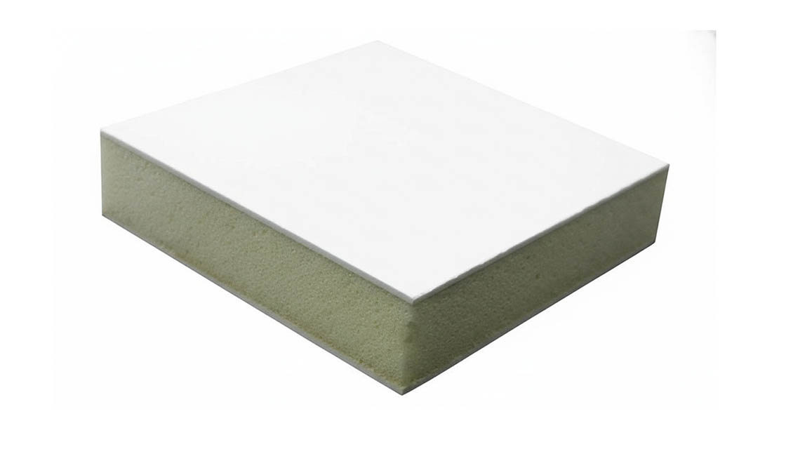
An 18mm GRP sandwich panel consists of two outer skins made from glass-reinforced plastic (GRP/FRP) bonded to a lightweight core material. The core is typically a foam such as PET, PVC, XPS, or PU, or a honeycomb structure like PP or fiberglass. This three-layer construction delivers high strength-to-weight performance while remaining waterproof and thermally insulating.
How do XPS, PVC, and PET foam cores differ?
PVC foam offers the best mechanical strength and is ideal for structural flooring and bulkhead applications. PET foam provides excellent thermal stability and is preferred for refrigerated transport where temperature consistency matters. XPS is the most cost-effective option for lighter-duty applications but has lower compressive strength than PVC or PET. Choosing the wrong core for your load requirements is a common engineering mistake.
How much does an 18mm GRP panel weigh?
The weight of an 18mm GRP sandwich panel depends on the core material and facing selection. Panels with PVC or PET foam cores typically range from 8 to 14 kilograms per square meter. Honeycomb-core variants can be significantly lighter, often under 6 kg per square meter. This weight advantage over aluminum makes GRP panels especially valuable for RV and truck applications where payload optimization is critical.
Are 18mm GRP panels fire retardant?
Yes, 18mm GRP sandwich panels from RaxPanel carry Class 1 fire ratings, meeting stringent fire safety standards for transport and construction applications. The GRP facing and core materials are selected and tested to resist flame propagation. For applications with higher fire-risk requirements, PIR-core variants are also available as an upgraded fire-performance option.
What is the thermal conductivity of these panels?
Thermal conductivity varies by core material, with PET and PU foams offering the lowest values for superior insulation performance. This makes 18mm GRP sandwich panels well-suited for refrigerated truck bodies and cold-chain logistics where temperature control directly impacts operational efficiency. The combination of structural integrity and thermal insulation in a single 18mm panel eliminates the need for additional insulating layers.
Can 18mm GRP panels be customized?
Yes, RaxPanel offers full customization of 18mm GRP sandwich panels including facing material, core type, panel dimensions up to 12 meters in length, and specialized surface treatments. Their engineering team conducts experimental testing to ensure customized panels meet your specific load, thermal, and environmental requirements. This flexibility allows you to optimize panel specifications for your exact application rather than adapting to off-the-shelf limitations.
How is panel quality verified before shipment?
RaxPanel verifies quality through experimental testing against strict data standards, including flexural strength tests, shear strength measurements, and water absorption checks kept below 0.5 percent. Their proprietary thermal lamination technology ensures glue-free bonding with superior shear strength under vibration, outperforming standard glued alternatives. With over 15 years of production experience and a daily output exceeding 1,700 square meters, quality consistency is built into every panel.