

Most facility teams obsess over hitting ISO classification on paper — then watch particle counts drift and energy bills climb the moment the cleanroom goes live. A cleanroom layout isn’t just a compliance checkbox. It’s the structural foundation that determines whether your space maintains stable contamination control for years or becomes a costly retrofit nightmare. Get the airflow paths, pressure cascades, and personnel-to-material separation wrong during planning, and no amount of HEPA filter upgrades will fix it later.
At RaxPanel, we’ve designed and supplied modular cleanroom panel systems for semiconductor, pharmaceutical, and biotech facilities for over a decade. Modular construction alone can cut installation time by 50% compared to stick-built conventional methods — but speed means nothing if the underlying layout doesn’t support your GMP classification, energy targets, and expansion plans. The difference between a cleanroom that passes audit and one that consistently fails comes down to decisions made on day one.
This guide walks through the critical planning decisions that separate compliant, efficient facilities from expensive mistakes — from mapping your workflow and zoning pressure differentials to avoiding the common layout errors that trigger costly retrofits. You’ll leave with a practical framework for evaluating your site constraints, selecting the right cleanliness grade, and designing a layout that holds up under regulatory scrutiny and day-to-day operations.

What a Cleanroom Layout Is and Why It Matters
A cleanroom layout is not merely a floor plan; it is a strategic architectural framework designed to control particle migration, pressure differentials, and human behavior to ensure consistent sterility and operational output.
Defining the Scope of a Cleanroom Layout
At its core, a cleanroom layout defines the spatial relationship between critical process zones, support areas, and transition spaces. Unlike standard facility design, which prioritizes flexibility or aesthetics, a cleanroom layout prioritizes contamination control logic above all else. It dictates how air moves, where pressure cascades occur, and how personnel interact with the environment. The scope encompasses everything from the placement of structural walls and ceilings to the positioning of fixed equipment and pass-throughs. It establishes the “geography” of the facility, determining the boundaries between “clean” and “dirty” areas to physically prevent cross-contamination before it can even begin.
For beginners, it is helpful to visualize the layout as a one-way street system. Just as a city uses one-way streets to prevent traffic collisions, a cleanroom layout uses unidirectional flow principles to prevent particles from colliding with sterile products. The layout determines the sequence of operations—from raw material entry to final packaging—and ensures that the physical environment supports this sequence without introducing turbulence or stagnation points where contaminants could settle.
Impact of Room Flow on Contamination Control
The physical layout is the primary driver of airflow behavior. In a controlled environment, air acts as the transport mechanism for particles. If the layout obstructs the intended airflow path, it creates turbulence or “dead zones” where particles can accumulate. For instance, placing a large workstation incorrectly can block laminar airflow, causing clean air to swirl and mix with potentially contaminated air. An effective layout ensures that physical barriers and equipment align with the room’s airflow pattern, allowing the air to sweep particles away from critical areas rather than trapping them.
Furthermore, the layout establishes the pressure cascades essential for contamination control. By arranging zones in a specific gradient—from high pressure in the cleanest areas to lower pressure in less critical areas—the layout creates a physical barrier where air naturally flows outward, preventing dirty air from seeping into clean spaces. If the layout does not account for these pressure relationships, seals are overwhelmed, and the entire environmental control system fails, regardless of how powerful the HVAC units are.
Linking Layout Design to Operational Efficiency
While contamination control is the mandate, operational efficiency is the viability metric. A poorly conceived layout forces operators to take unnecessary steps or cross through incompatible zones, increasing the risk of human-generated contamination and reducing throughput. Efficient layout design minimizes the movement of personnel and materials, reducing the time spent in gowning rooms and the frequency of door openings. Every time a door opens or a person moves rapidly, they generate particles; a streamlined layout reduces these events, directly supporting cleanliness goals.
From a B2B perspective, the layout also impacts the total cost of ownership (TCO). An optimized layout reduces the length of utility runs (electrical, piping, gas) and minimizes the square footage required for airlocks and buffers, lowering both construction and energy costs. It ensures that expensive filtration capacity is focused exactly where the process demands it, rather than wasted on oversized transition areas. By aligning the physical space with the logical flow of production, the layout reduces cycle times and labor costs while maintaining strict compliance with standards like ISO 14644-1.

What to Evaluate Before You Start Designing
Before you commit a single line to CAD, you must validate the physical realities of your facility. The most common cause of cleanroom project delays isn’t the HVAC design; it is discovering that the existing floor slab cannot support the load or that ceiling plenum space is insufficient for ductwork.
Assessing Existing Site and Structural Constraints
You cannot design a high-performance layout in a vacuum. The physical envelope of your existing building dictates the feasible geometry of your cleanroom. Engineers must start by analyzing the structural integrity of the floor slab. While concrete is robust, heavy traditional wall systems or dense equipment banks can push older slabs past their yield point. This is particularly critical for pharmaceutical or electronics cleanrooms located on upper levels of a building.
In our experience with retrofit projects, utilizing lightweight composite panels is often the deciding factor between a feasible project and a structural reinforcement nightmare. By selecting advanced core materials like PP honeycomb or CFRT, the dead load of the wall and ceiling structure is significantly reduced compared to traditional mineral wool or concrete-based systems, allowing for installation on standard mezzanine floors without costly steelwork reinforcement.
Simultaneously, you must audit the vertical dimension. Do not assume your ceiling height is available for the cleanroom itself; you must deduct the depth of the lighting grid, the HEPA filter housing, and most importantly, the return air plenum. If your existing ceiling height is marginal, a flush-mount ceiling system using thinner high-strength composite panels may be required to maximize functional interior height.
Always locate the existing structural columns and roof trusses before layout planning. Columns often dictate the module width of your cleanroom panels. For example, if your bay width is 4.5m, standard 1150mm or 1200mm wide panels can fit efficiently, whereas non-standard column spacing may force expensive custom panel cuts and wastage.
Mapping Out Process and Equipment Requirements
A layout is only as good as the data it is built upon. Before placing walls, you must aggregate detailed equipment specifications. Do not rely on brochure footprints; request “service clearance” drawings from your equipment manufacturers. This includes space for operator access, maintenance doors, and tool change areas. A common failure point is designing a tight corridor that cannot accommodate a trolley carrying a change-part filter or a forklift lifting a vessel lid.
You must also map the utility nodes. Identify the exact location of drainage points, nitrogen drops, and high-power electrical panels. In cleanroom design, you want to minimize horizontal runs of utilities inside the clean zone to reduce particulate traps. This often means placing heavy process utility walls adjacent to non-clean mechanical corridors.
| Data Point | Why It Matters for Layout |
|---|---|
| Operational Footprint | Ensures clearance for operator movement and safety zones around machinery. |
| Heat Load (kW) | Determines HVAC capacity and dictates the placement of exhaust/cooling vents. |
| Vibration Sensitivity | May require isolation zones or separation from heavy air handling units (AHUs). |
| Process Drainage | Dictates floor slope requirements and location of trapped floor drains. |
Analyzing Personnel and Material Traffic Patterns
Contamination control is fundamentally about managing the movement of people and goods. Before finalizing the layout, you must conduct a traffic analysis. This is not just about “how many people,” but “when and how.” Calculate the peak occupancy at shift change. If you have 20 operators entering simultaneously, your airlock or gowning room must be sized to handle this volume without creating a bottleneck that forces personnel to rush—a major cause of gowning breaches.
For materials, analyze the size and frequency of incoming raw materials and outgoing finished goods. If you are moving pallets via forklift or AGV, your corridors and transfer hatches must be dimensioned accordingly. Standard 1200mm x 1000mm pallets require a minimum clear opening of 1300mm–1400mm to pass through easily without damaging door frames or wall panels.
This traffic assessment directly influences the durability specifications of your wall system. High-traffic material corridors are subject to impact from carts and pallet jacks. While generic smooth panels are sufficient for low-traffic core zones, we recommend specifying high-impact resistant surfaces, such as fiberglass reinforced sheets with a heavy-duty gelcoat, for entry chutes and material airlocks to prevent chipping and delamination over the facility’s lifecycle.
- Peak Shift Flow: Calculate the maximum number of personnel entering/exiting during shift changes to size airlocks and gowning benches correctly.
- Material Dimensions: Verify the largest standard skid or tote size used in your supply chain to ensure doorways and pass-throughs accommodate them.
- Turnover Frequency: High-frequency material entry points require more robust wall protection and easier-to-clean surfaces to withstand repeated wash-downs.
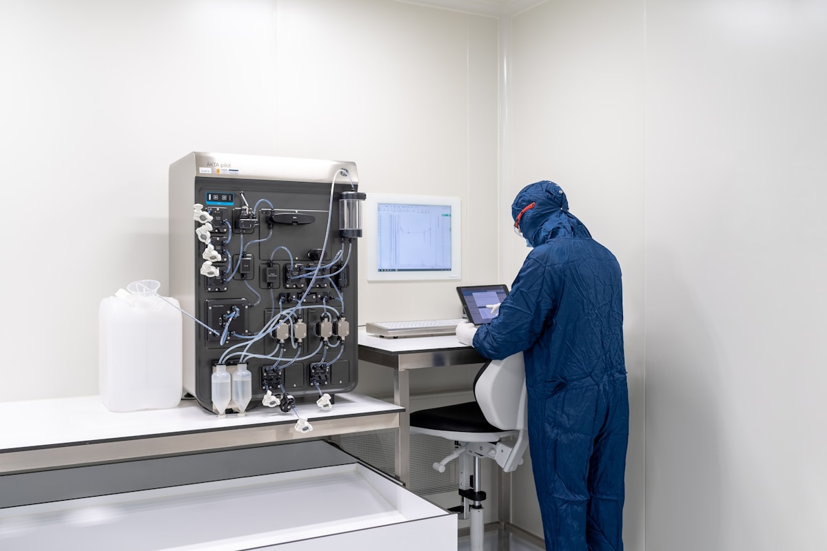
What Cleanliness Grade Your Cleanroom Needs
Selecting the correct cleanroom classification is the single most critical decision in the design phase, as it dictates your capital expenditure, operational energy costs, and compliance risk. Choosing a grade that is too strict wastes resources, while a grade that is too lenient guarantees regulatory failure.
Determining the appropriate cleanliness grade requires aligning your facility’s output with international standards, primarily ISO 14644-1 for general industries and GMP (EU Grade A/B/C/D) for pharmaceuticals. The “grade” defines the maximum allowable particle count per cubic meter of air. For project stakeholders, the challenge is not just understanding these numbers, but translating them into physical infrastructure requirements. Your target grade drives the selection of wall and ceiling materials, the complexity of the HVAC system, and the necessary pressure differentials.
The Financial Trap of Over-Engineering
A common mistake in facility planning is the “safety margin” fallacy—designing for a higher grade than necessary “just to be safe.” In cleanroom economics, the cost curve is exponential, not linear. Moving from an ISO 8 (Class 100,000) environment to an ISO 5 (Class 100) environment does not simply double your costs; it can multiply HVAC energy consumption and construction complexity by a factor of five or more.
Higher grades require dramatically increased air changes per hour (ACH) to dilute contaminants. This demands powerful air handling units, higher-density fan filter units (FFUs), and wall systems capable of withstanding immense internal pressure without leakage. If your manufacturing process only requires an ISO 7 environment for general assembly, investing in ISO 5 panel specifications and airflow infrastructure is a capital waste that will bleed your operational budget for years.
How Grade Dictates Panel and Architecture Choices
The cleanliness grade directly determines the physical properties of the enclosure. In lower-grade environments (ISO 8 or ISO 9), standard modular sandwich panels with galvanized steel or aluminum facings are typically sufficient. These structures prioritize cost-effectiveness and basic thermal insulation. However, as you move toward stringent classifications (ISO 5 and above), the wall system becomes a critical component of contamination control.
- Surface Integrity: ISO 5 and GMP Grade A environments require non-porous, non-shedding, and chemically resistant surfaces. Smooth gel-coated Fiberglass Reinforced Polymer (FRP) or Stainless Steel facings are mandatory to prevent particle entrapment and allow for rigorous sterilization protocols (like VHP).
- Airtight Sealing: High-grade rooms cannot tolerate air leakage. Joints must utilize thermal-gasketed cam-lock systems rather than simple mechanical fasteners to ensure the envelope is hermetically sealed, maintaining the precise pressure cascades required to push contaminants outward.
- Structural Insulation: To prevent condensation—which breeds biological contaminants—panels in high-humidity or sterile environments often utilize PIR (Polyisocyanurate) or PU cores with superior thermal performance compared to basic materials.
Industry-Specific Classification Benchmarks
While standards vary, certain benchmarks exist across sectors. In the semiconductor industry, the requirement is driven by the micro-feature size of the chip; as nodes shrink below 5nm, the requirement often shifts from ISO 3 toward ISO 1 or 2, necessitating rigid hardwall construction with ultra-flat seamless surfaces to prevent airflow turbulence.
Conversely, the pharmaceutical industry operates on a “zoned” approach defined by GMP. A sterile filling line requires a localized ISO 5 (Grade A) zone (the critical point) surrounded by an ISO 7 (Grade B) background. You rarely build an entire plant at ISO 5. Instead, you use modular partitions to create high-grade “islands” within a lower-grade room. This is where advanced lightweight materials, such as honeycomb composite panels, provide a distinct advantage by allowing structural reinforcement for heavy equipment on upper floors without adding prohibitive dead weight.
Future-Proofing Grade Requirements
Process requirements evolve. A medical device manufacturer starting with ISO 7 packaging may eventually need ISO 5 assembly lines. Retrofitting a traditional stick-built cleanroom is a construction nightmare involving demolition and dust. Modular composite panel systems offer inherent scalability.
When planning your initial layout, design the utility infrastructure and panel orientation to accommodate future upgrades. Ensure your ceiling grid can support the addition of higher density HEPA filters and that your wall panels can be reconfigured to expand the cleanroom footprint or create stricter airlocks. By selecting a modular system with interchangeable components and reserved utility pathways, you allow the facility to graduate to a higher cleanliness grade without requiring a total teardown.
| ISO Classification | Max Particles (≥0.5µm/m³) | Air Changes/Hour | Typical Application | Panel & Layout Requirement |
|---|---|---|---|---|
| ISO 1–4 | 10–877 | 400–600+ | Nanotechnology, advanced semiconductor fabrication, precision optical manufacturing | Hardwall construction with Class A fire rating (GB8624); ultra-smooth seamless panel surfaces; specialized thermal-breaking joints; strict flatness tolerance to prevent airflow dead zones and turbulence |
| ISO 5 | 3,520 | 200–600 | Sterile pharmaceutical filling, Grade A areas, semiconductor lithography | Hardwall modular system; airtight sealed joints; smooth non-porous surface (SUS304 or gelcoat FRP); thermal-gasketed cam-lock connections to prevent condensation |
| ISO 6 | 35,200 | 60–200 | High-risk food processing (ready-to-eat, infant formula), medical device assembly, biotech cell culture | Modular sandwich panel walls (50–100 mm); PIR or PU core for thermal insulation; pressure-differential zoning with cascading airflow from ISO 5 → ISO 6 |
| ISO 7 | 352,000 | 20–60 | Pharmaceutical formulation (Grade C), surgical instrument assembly, implant manufacturing, compounding pharmacies | Modular wall layout design with HEPA-covered ceiling; 50–150 mm sandwich panels; CFRT or honeycomb core for lightweight retrofit on upper floors; seamless corner joints for VHP compatibility |
| ISO 8 | 3,520,000 | 10–25 | Medical device packaging, food beverage filling (dairy, bottled), general pharmaceutical packaging, clean utility areas | Softwall or rigidwall modular panels (50 mm); galvanized steel or aluminum facing; cost-effective thermal insulation (XPS/PU core); pressure differential maintained at +10–15 Pa above adjacent zones |
| ISO 9 (Cleanroom Boundary) | 35,200,000 | <10 | Supporting corridors, gowning anterooms, material airlocks, HVAC plant rooms adjacent to controlled spaces | Standard sandwich panel partitions (50 mm); pressure differential layout ensures cascading airflow from higher-grade zones; HPL or coated steel facing for easy decontamination |

How to Map Workflow and Movement Through Your Space
Effective workflow mapping relies on unidirectional flow: moving personnel, materials, and processes from “dirty” to “clean” areas in a linear sequence to prevent cross-contamination and particle recirculation.
Mapping workflow is essentially creating a “string diagram” for your facility. You must trace the exact path of every material and person from the moment they enter the building to the moment they leave. In a cleanroom environment, this is not just about efficiency; it is a contamination control strategy. The fundamental rule is linear progression. You never want a packaged, sterile product to pass by a raw, unprocessed material. If your map shows lines crossing over each other, your layout is introducing unnecessary risk.
The Principle of Unidirectional Flow
Think of your cleanroom workflow like a river flowing downstream. It should move continuously in one direction without eddies or backtracking. This principle applies to both people and goods. When movement is unidirectional, the air currents (which typically flow from clean to less clean areas) assist in pushing contaminants away from the critical process zones, rather than dragging them back in.
- Personnel Flow: Personnel should move from the locker room, into the gowning room, through an airlock or interlock, and finally into the production core. They should exit via a different path or a dedicated exit door to prevent “dirty” street clothes from re-entering the gowning area.
- Material Flow: Raw materials enter through a receiving dock, move to staging, pass through a material airlock or pass-through with disinfection, and proceed to the production line. Finished goods should exit via a separate route to avoid touching the incoming raw material stream.
Step-by-Step Mapping Guide
To visualize this effectively, you do not need advanced software. A simple pencil and paper sketch is often the best way to start. The goal is to expose inefficiencies and contamination risks before any walls are built.
📋 Actionable Mapping Steps
- Step 1: List Every Process. Write down every single action that happens in the space. Do not just write “manufacturing.” Break it down: “Receiving,” “Unpacking,” “Sterilization,” “Assembly,” “Testing,” and “Packaging.”
- Step 2: Assign Cleanliness Grades. Next to each process, assign the required ISO classification (e.g., ISO 8 for receiving, ISO 5 for critical assembly). This immediately tells you where walls and airlocks are needed.
- Step 3: Draw the Connection. Draw arrows connecting the steps in the order they occur. Ensure the arrow goes from lower cleanliness (higher ISO number) to higher cleanliness (lower ISO number).
- Step 4: Identify Cross-Overs. Look at your drawing. Do any lines cross? If a “Finished Goods” line crosses a “Raw Material” line, you have identified a contamination risk that requires a layout change or a physical barrier.
- Step 5: Locate Buffer Zones. Mark the transition points between different grades. These are your airlocks, gowning rooms, and pass-through windows. These spaces act as the “pressure seals” between zones.
Avoid placing high-traffic equipment like forklifts or waste disposal bins near the main entrance of the critical clean zone. Heavy traffic creates turbulence and stirs up particles from the floor, compromising the filtration efficiency of the entire room.
Minimizing Touchpoints and Friction
Once you have the sequence, refine it. The fewer touchpoints—places where a person or material must stop, open a door, or wait—the better. Every door opening is a disruption to the pressure cascade. Modern cleanroom design often uses automated sliding doors or rapid-roll doors to minimize the time an opening is exposed. When mapping, count the doors. If a product has to pass through five different doors to get from point A to point B, your workflow is too complex. Consolidate zones where possible to reduce the number of transitions.
Designing Airflow and Pressure Zones for Your Cleanroom
Understanding the Pressure Cascade
Designing an effective cleanroom starts with understanding that air behaves like water: it naturally flows from areas of high pressure to areas of low pressure. In cleanroom design, engineers utilize this physics to create a “pressure cascade.” By maintaining higher air pressure in the cleanest zones and incrementally lower pressure in less clean areas, you ensure that when doors are opened or leaks occur, air flows outward rather than inward. This invisible barrier physically pushes potential contaminants away from critical processes, preventing them from migrating into sterile environments.
Imagine the cleanroom as a series of aquariums connected by tubes. If the water level in the main tank is higher than the side tanks, water will only flow out, never allowing dirty water to rush back in. This hierarchy is essential for maintaining cleanliness standards without relying entirely on filtration, saving significant energy and operational costs over the lifespan of the facility.
Airflow Patterns: Laminar vs. Turbulent
Once pressure is established, the pattern of airflow determines how particles are removed. There are two primary patterns utilized in the industry, each suited to different classification levels and operational needs.
- Unidirectional (Laminar) Flow: Often described as “laminar,” this system moves filtered air in a single, uniform direction—typically vertically from the ceiling to the floor—at a constant velocity. Think of it as a sheet of glass sliding through the room; it sweeps particles away instantly and prevents them from settling. This is critical for high-classification zones where even microscopic airborne contaminants can ruin a product, such as in aseptic filling or semiconductor manufacturing.
- Non-Unidirectional (Turbulent) Flow: Also known as turbulent flow, this introduces air through high-efficiency filters in the ceiling, but the air mixes with the room air before being extracted through low wall returns. While it sounds chaotic, the goal is dilution rather than sweeping. This is the standard for general manufacturing or lower-grade cleanrooms (ISO Class 7 and higher) where perfect particle removal is less critical than cost-effective ventilation.
Choosing the wrong airflow pattern is a common root cause of contamination. Laminar flow requires significant energy, while turbulent flow requires careful air change management to prevent dead zones.
The Critical Role of the Building Envelope
A sophisticated HVAC system is useless if the physical room leaks. The “building envelope”—comprising the walls, ceilings, and floor—acts as the vessel that holds the pressure. If there are gaps in panel joints or around utility penetrations, the expensive air you are conditioning will escape, causing pressure differentials to collapse and allowing dirty air to infiltrate.
To ensure the envelope performs as designed, modern cleanrooms utilize composite panel systems with specific features designed for airtightness. For instance, cam-lock mechanisms combined with continuous gaskets provide a secure seal that prevents air leakage, which is essential during high-pressure sterilization cycles like VHP (Vaporized Hydrogen Peroxide). additionally, thermal breaks within the panel structure are vital; they prevent temperature differences between the inside and outside of the cleanroom from causing condensation, which can lead to mold growth and become a source of contamination that disrupts airflow patterns.
Validation and Smoke Studies
The design phase ends with validation. Engineers use smoke studies to visualize the airflow patterns, ensuring there are no “dead zones” where air stagnates and particles accumulate. These visual tests confirm that the air cascades correctly from clean to less clean areas and that the return air pathways are unobstructed. This step is not just a regulatory checkbox; it is the proof that your theoretical design works in physical reality.
| Parameter | Specification | Design Requirement | Validation Method |
|---|---|---|---|
| Pressure Differential | 10-15 Pa between adjacent zones | Hierarchical pressure cascade from cleanest to least clean area | Manometer testing per ISO 14644-2 |
| Airflow Pattern | Unidirectional (laminar) or Non-unidirectional (turbulent) | Class 5 zones require unidirectional flow at 0.45 m/s ±20% for contamination control | Smoke study visualization per ISO 14644-3 |
| Panel Joint Seal | Airtight gasket or silicone sealant | Maintain pressure differential integrity during VHP sterilization cycles | Pressure decay test and leak rate verification |
| Thermal Break Requirement | Cam-lock systems with thermal gaskets | Prevent condensation and thermal bridging in cold room/pharma cleanrooms | Thermal imaging survey |
| Panel Surface Finish | Smooth, non-porous (e.g., Gelcoat, Stainless Steel) | Minimize particle accumulation and enable effective CIP/SIP cleaning | Visual inspection and surface roughness (Ra) measurement |
| HVAC Air Changes | Class 7: 20-40 ACH; Class 8: 10-20 ACH | Sufficient dilution ventilation to maintain particle counts within ISO 14644 limits | Particle counting per ISO 14644-1 |
| Modular Panel Thickness | 50mm-200mm configurable | Optimize thermal insulation (R-value) relative to structural load requirements | Thermal bridging assessment and structural load calculation |
Planning Separate Paths for People and Materials
Separating human and material flow paths is one of the most critical contamination control strategies in cleanroom design. Mixing these pathways dramatically increases the risk of cross-contamination and ISO classification failure.
Why Separate Paths Matter
Cleanrooms are designed to maintain specific particulate and microbial limits. When personnel and materials share the same entry routes, contamination vectors multiply. Personnel carry skin cells, fibers, and microbes from the outside environment. Materials entering the cleanroom often arrive with packaging debris, dust, and surface contaminants. Combining these two streams in a single corridor or doorway creates a contamination hotspot that can compromise entire ISO classification zones.
Post-construction realization of mixed traffic vectors frequently necessitates costly structural and HVAC revalidation. The financial and operational risks are substantial: facility managers often discover after construction that mixed personnel traffic and material flow paths have created persistent contamination issues. Correcting these problems post-build demands expensive retrofits—reconfiguring walls, reinstalling HVAC zoning, and potentially revalidating the entire cleanroom—each step compounding downtime and budget overruns. Planning separate paths from the initial design stage eliminates this risk entirely.
Personnel Entry: Gowning Areas and Airlocks
Personnel must transition from the normal environment into the cleanroom through a structured gowning sequence. This typically involves a multi-stage airlock system where workers remove street clothing, shower or change into cleanroom garments, and progressively don increasingly clean attire at each stage. Each gowning room serves as a pressure barrier, with air flowing from cleaner to dirtier zones to prevent contamination backflow.
The gowning process generally follows this progression:
- First changing area: Removal of outer garments and shoes, with storage lockers
- Second changing area: Donning of cleanroom coveralls, hair covers, and face masks
- Third changing area (for higher classifications): Glove donning, boot covers, and final sanitization
- Airlock or pass-through: Final pressure-buffered transition into the cleanroom proper
Each transition zone must maintain a pressure differential of at least 10 to 15 Pascals relative to the next zone. This pressure cascade ensures that air always flows from the cleanest area toward the least clean area, preventing contaminated air from migrating into controlled spaces.
Material Entry: Pass-Through Systems and Decontamination
Materials entering the cleanroom require their own dedicated pathway, distinct from personnel routes. This pathway typically includes a receiving area, a decontamination zone, and a pass-through system that transfers materials into the cleanroom without breaching the environmental envelope.
Pass-through systems come in several configurations. Small items such as tools, samples, and components typically move through pass-through hatches—sealed chambers with interlocking doors that prevent both sides from opening simultaneously. Larger materials and equipment may use pass-through airlocks, which function as miniature rooms with their own ventilation and filtration. For high-contamination-risk materials, a dedicated stripping and cleaning room sits between the receiving area and the pass-through system.
The pass-through chamber itself must be constructed with materials that resist microbial growth and can withstand repeated cleaning with harsh sanitizers. Sandwich panels with smooth, non-porous facings—such as those with GRP/FRP skins or coated metal facings and foam cores like XPS, PET, or PU—provide excellent durability and cleanability for these critical barrier structures.
Designing the Physical Separation
The physical layout must ensure that personnel and material paths never intersect within the cleanroom envelope. This means separate exterior doors, distinct corridor routes, and isolated gowning and decontamination rooms. The separation should be maintained through walls and doors that are structurally continuous—no shared openings, no overlapping door swings, and no shared utility penetrations that could compromise the pressure barrier.
Key design principles for maintaining separation include:
- Dedicated entry points: Personnel doors and material loading docks should be on opposite sides of the facility when possible, or at minimum separated by a physical barrier wall
- Corridor separation: Personnel corridors and material handling corridors should not share the same ceiling plenum or wall cavity, which could allow air migration between paths
- Pressure zoning: Each path should have its own HVAC zone with independent pressure control, preventing air from one path bleeding into the other
- Door interlocking: All doors at path boundaries should use electric interlocks that prevent simultaneous opening, maintaining the pressure barrier at all times
Modular cleanroom panel systems simplify this separation by allowing rapid construction of independent corridor runs and dedicated rooms without compromising the airtight integrity of the envelope. Panels with integrated gasketed joints and sealed utility penetrations maintain the pressure differential required for effective path separation.
Common Pitfalls in Path Separation
Another common error is underestimating the space required for proper gowning sequences. A single-room gowning area may seem sufficient initially, but as cleanroom classification requirements tighten or production scales up, operators will find themselves rushing through gowning steps or skipping stages entirely. Planning for at least two dedicated gowning rooms with adequate square footage per occupant prevents this operational degradation.
Material path design also suffers from insufficient pass-through sizing. Engineers sometimes specify pass-through hatches that are too small, forcing operators to angle items through at awkward angles that damage the chamber seals or take excessive time. Always size pass-throughs to accommodate the largest item that will regularly traverse them, plus a 20% margin for handling clearance.
Validating Path Separation Performance
After construction, path separation effectiveness should be validated through pressure differential mapping and particulate monitoring. Each gowning room and pass-through chamber should be tested under normal operating conditions to confirm that pressure cascades remain stable and that no air mixing occurs between the personnel and material pathways. Particulate counts should be measured simultaneously in both paths during active material transfer and personnel gowning to verify that cross-contamination is not occurring.
Ongoing monitoring should include real-time pressure differential alarms at each barrier point. If a pass-through door fails to close properly or a gowning room door is left open, the pressure cascade should break instantly and trigger an alert. This early warning system allows operators to correct issues before they compromise the cleanroom classification.
Integrating Modular Panel Systems for Path Separation
Modular cleanroom construction offers significant advantages for implementing separate人流 and物流 paths. Sandwich panel systems—available with multiple core materials including XPS, PET, PU, PVC, and honeycomb structures—provide the structural rigidity, thermal insulation, and airtight seal required for maintaining pressure differentials across multiple zones. These panels can be configured into custom wall and ceiling assemblies that create independent corridor runs, dedicated gowning rooms, and sealed pass-through chambers without the thermal bridging or air leakage common in traditional construction methods.
The modularity of these systems also supports future reconfiguration. If production needs change and path separation requirements evolve, the panel-based walls and doors can be disassembled and repositioned with minimal disruption to ongoing cleanroom operations. This adaptability is particularly valuable for facilities that anticipate scaling classification levels or adding new production lines over time.
When specifying panels for gowning rooms and pass-through chambers, prioritize facings that resist repeated sanitization and cores that provide both structural strength and thermal insulation. GRP/FRP-faced panels with foam or honeycomb cores offer excellent chemical resistance and dimensional stability, while aluminum-faced variants provide superior durability in high-abrasion environments. The choice depends on the specific contamination control requirements and cleaning protocols of your cleanroom classification.
Coordinating Utilities While Keeping Zones Airtight
Every penetration through a cleanroom wall or ceiling is a potential leak path. Successful utility coordination requires planning penetrations before panel installation and using certified airtight seal assemblies rated for the pressure class of each zone.
Why Utility Penetrations Break Airtight Boundaries
Cleanroom zones depend on differential pressure cascades to control contamination flow. Positive pressure rooms push air outward; negative pressure rooms contain hazardous agents inside. Every pipe, conduit, duct, or cable that passes through a partition creates a discontinuity in the airtight envelope. Even a 2 mm gap around a conduit can become a measurable leak path under pressure testing.
The core conflict is simple. HVAC systems, lighting, power outlets, process gases, and data cabling all need to reach the cleanroom interior. Each one requires a penetration. Each penetration must be sealed without compromising the panel’s structural integrity or the zone’s pressure boundary. This is where many projects encounter costly rework.
Coordinating Lighting and Electrical Penetrations
Lighting and electrical fixtures represent the largest group of ceiling penetrations in a standard cleanroom. The key is to specify airtight gasketed housings designed for cleanroom use. These fixtures integrate a continuous seal ring between the housing flange and the panel surface, eliminating the gap that standard commercial fixtures leave exposed.
Electrical conduits running through partitions require two sealing points: one at the panel face and one inside the plenum space. Conduit bushings with compressible elastomer grommets create a pressure-rated seal around each cable or pipe. For multiple small-diameter cables, a bulkhead connector with a single gasketed face plate is more reliable than individual sealed entries.
Always map every lighting and electrical penetration on the ceiling plan before panels are fabricated. Prefabricating panel openings with reinforced sleeves ensures the seal surface remains flat and continuous after installation.
HVAC Duct Penetrations and Pressure Integrity
HVAC is the most critical utility system in a cleanroom. Supply air, return air, and exhaust ducts must pass through walls and ceilings to maintain airflow patterns and pressure differentials. Each penetration point is a structural weak point if not properly sealed.
The standard approach uses a sleeve-and-flange assembly. A rigid metal or composite sleeve is embedded in the panel during fabrication. The duct connects to the sleeve with a flanged gasketed joint. This creates a continuous airtight path from the duct interior through the panel thickness to the room interior. The joint between the sleeve and the panel face must be sealed with a certified cleanroom sealant that remains flexible over the project lifespan.
For variable air volume (VAV) boxes and dampers located within the ceiling plenum, the plenum itself must be part of the pressure boundary. This means the ceiling tiles or panels above the plenum must also be sealed at every joint and penetration, effectively creating a pressurized plenum chamber. Unsealed plenum spaces allow air to bypass the designed pressure cascade and defeat the zoning strategy.
Process Gas and Utility Penetrations
Process gases such as nitrogen, argon, and compressed air are common in semiconductor and pharmaceutical cleanrooms. These gas lines require dedicated penetrations with secondary containment where safety standards demand it. Each gas line penetration needs a sealed bulkhead fitting rated for the operating pressure and gas type.
Utility lines for water, purified water, and chemical supply follow the same principle. Every penetration point must have a documented seal assembly with a specified torque value for compression fittings. Field adjustments without resealing are a leading cause of pressure test failures during certification.
Sealing Methods That Work Under Pressure Testing
Pressure testing validates every seal in the system. The test pressurizes each zone to its design differential and measures decay rate over a set period. Any seal that leaks will show up as a pressure drop. The following sealing methods are proven to pass certification:
- Gasketed fixture housings: Lighting and electrical fixtures with integrated continuous seal rings pass pressure testing when installed on flat panel surfaces with proper torque.
- Embedded sleeves with flanged duct connections: Duct penetrations sealed at both the sleeve-to-panel interface and the flange-to-duct interface maintain integrity at 25 Pa to 50 Pa differential pressures.
- Compressible elastomer grommets: Cable and small-conduit penetrations sealed with dual-durometer grommets accommodate minor panel movement without losing seal contact.
- Sealant-backed bulkhead connectors: Multi-cable or multi-pipe bulkheads with a single gasketed face plate reduce the number of individual seal points and lower failure risk.
Planning penetrations before panel fabrication
The single most effective way to avoid airtight failures is to finalize all utility penetration locations before panels are manufactured. Once a panel is fabricated, adding a penetration requires cutting through the facing material, which compromises the factory seal and introduces a field-applied seal that is harder to certify.
A coordinated utility routing plan should include the exact size, location, and seal method for every penetration. This plan should be cross-referenced against the architectural drawing, the HVAC layout, and the electrical riser diagram. Any conflict between disciplines must be resolved before the panel shop begins production.
Plenum sealing as part of zone airtightness
The ceiling plenum is often overlooked in airtightness planning. Utility penetrations into the plenum, access hatches, and joint seals between ceiling panels all contribute to plenum leakage. If the plenum is not sealed, air can short-circuit from a positive pressure supply zone to a negative pressure return zone through the plenum space, bypassing the room boundaries entirely.
Sealing the plenum means treating the ceiling assembly as a continuous pressure boundary. Every ceiling panel joint, every light housing flange, and every access door in the plenum must use the same gasketed seal methodology as the wall partitions. This approach ensures that the pressure cascade flows through the intended room paths and not through hidden bypass routes.
Compromising the integrity of the ceiling assembly through post-installation modifications guarantees a failure during pressure integrity testing. When openings are cut after panels are in place, the continuous pressure boundary described in the plenum sealing methodology is broken at every unsealed joint, flange, and access point. These unapproved penetrations bypass the gasketed seal system and create uncontrolled leakage paths that cascade through the pressure zone. Because the sealant or gasket application cannot be verified to specification, certification auditors will flag these field modifications as non-compliant, directly resulting in test failure. Always finalize the penetration schedule before fabrication begins to preserve the ceiling assembly as a unified pressure boundary.
Documentation for certification
Every sealed penetration must be documented for cleanroom certification. The record should include the penetration location, the seal method used, the sealant or gasket product specification, and the installer’s identification. Certification auditors and facility engineers rely on this documentation to verify that each penetration meets the pressure class of its zone.
A penetration schedule spreadsheet linked to the as-built drawing is the industry standard. It allows quick cross-reference during annual re-certification and makes it straightforward to track which seals may need replacement after panel maintenance or modification.
Common Planning Mistakes That Lead to Costly Retrofits
The most expensive cleanroom errors originate at the planning stage. Neglecting airflow physics, blocking future scalability, and poor airlock positioning inevitably lead to contamination control failures and expensive structural retrofits.
Overlooking Airflow Dynamics and Pressure Cascades
One of the most pervasive failures in cleanroom design is treating airflow as an afterthought rather than a structural pillar of the layout. To maintain purity, air must move in a specific direction—usually from the cleanest area (like the filling zone) to the least clean area (like the corridor). This concept, known as the pressure cascade, requires a precise pressure differential (typically 10-15 Pascals) between rooms. If the layout does not account for the physical location of return air grilles or the placement of high-heat equipment, “dead zones” are created where air stagnates.
Imagine air moving like water in a river. If you place a large boulder (a piece of equipment) directly in the middle of the current, the water backs up and swirls behind it. In a cleanroom, these swirling eddies trap contaminants. Without careful planning of ceiling filter locations relative to the room’s process layout, laminar flow becomes turbulent, and particles settle on critical surfaces. Retrofitting HVAC ducts and ceiling grids to fix turbulence after construction is exponentially more costly than designing the flow path correctly during the initial architectural phase.
Never place return air grilles directly opposite supply filters without considering process obstructions. This “short-circuiting” causes fresh air to bypass the working area entirely, rendering the air change rate ineffective for contamination control.
Neglecting Future Expansion and Scalability Needs
Facility planners often optimize the cleanroom for current production targets, utilizing every available square foot of the floor plan to maximize immediate ROI. While this seems efficient initially, it creates a hard ceiling for growth. In the modular cleanroom industry, expansion should be a core component of the initial layout strategy. A common mistake is building the envelope flush against existing structural walls or immovable utility columns, leaving no physical space to add future modules.
Scalability planning involves reserving “ghost space” or blank wall panels that can be cut out and connected to new extension modules without halting operations. If the original design does not account for the load-bearing capacity of the ceiling grid to support additional filters, or if the HVAC system is sized without a buffer capacity, expanding later requires a total system overhaul. By neglecting to install removable bulkheads or reserve adequate electrical load capacity, owners condemn themselves to a costly retrofit where they must dismantle walls just to add a small gowning room or an additional processing station.
Inefficient Placement of Airlocks and Pass-Throughs
The positioning of airlocks and pass-through windows dictates the movement efficiency of both personnel and materials. A frequent layout error involves locating airlocks in areas that disrupt the unidirectional flow of the process, causing cross-traffic between clean and dirty zones. For instance, if a material airlock is placed too close to a high-traffic personnel door, the rush of air when people enter can pull contaminants out of the airlock and into the cleanroom.
Furthermore, undersizing these entry points is a critical failure mode that is difficult to fix later. Standard door widths are often insufficient for moving large equipment carts or raw material drums. Planners must verify that the swing radius of doors does not interfere with cleanroom operations and that pass-throughs are positioned at a height and depth that matches the ergonomic workflow of the operators. If a pass-through is placed on the wrong side of a wall relative to the supply chain flow, operators are forced to carry materials across the room, increasing particle generation and contamination risk.
- Cross-Contamination Risk: Airlocks must act as buffers, not shortcuts. Placing them incorrectly creates turbulence that defeats the purpose of pressure differentials.
- Equipment Clearance: Always measure the largest piece of machinery that will enter the room. Narrow doors or poorly placed pass-throughs will eventually require wall demolition to install new equipment.
- Workflow Disruption: Pass-throughs should be located near the “dirty” side of the process to minimize the distance raw materials travel through the clean environment.
Conclusion
Designing a cleanroom isn’t just about assembling wall panels. You must map airflow dynamics and pressure cascades before construction begins. If the workflow logic is flawed, contamination controls fail, forcing expensive retrofits later. Focus on personnel and material movement first. Get the flow right, and the efficiency follows naturally.
Our engineers have spent years refining modular wall systems to handle these exact pressure differential challenges. We can review your layout schematics to catch hidden bottlenecks. Don’t guess at the specifications. Use our manufacturing team as your technical sanity check to lock down a design that actually works on the floor.
Frequently Asked Questions
What ISO standards govern cleanroom panel specifications?
ISO 14644-1 defines airborne particulate cleanliness class limits, while ISO 14644-2 and -3 address design, construction, and testing requirements for cleanroom panels. Engineers must ensure all sandwich panels meet these standards for classification compliance. RaxPanel designs its modular cleanroom wall layout design solutions to align with these specifications, ensuring consistent performance across installations.
What is the difference between modular and permanent cleanrooms?
Modular cleanrooms use prefabricated sandwich panel systems that allow rapid reconfiguration, expansion, and relocation as process needs evolve. Permanent cleanrooms are constructed with fixed materials such as tiled or plastered walls and are not designed for modification. For facilities requiring flexibility or phased expansion, modular cleanroom wall layout design offers a more cost-effective long-term solution.
Can cleanrooms be installed on upper-floor structures?
Yes, lightweight composite panels such as CFRT and honeycomb-core sandwich panels significantly reduce structural load compared to traditional concrete or masonry construction. This enables cleanroom deployment on upper levels without expensive structural reinforcement. Engineers should verify floor load capacity with a structural consultant, but lightweight panel systems make retrofitting existing facilities economically viable.
What fire rating do cleanroom sandwich panels require?
Cleanroom panels should achieve at minimum Class A (GB8624) or Class 1 (ASTM E84) fire ratings, depending on regional code requirements. Core materials such as PIR and rockwool provide inherent fire resistance, while PU cores require additional treatment to meet classification standards. Specifying the correct fire rating during the design phase avoids costly retrofits and regulatory audit failures.
What core materials are suitable for cleanroom sandwich panels?
Common cleanroom core materials include PIR, PU, rockwool, XPS, PET foam, and honeycomb structures, each offering different thermal, fire, and weight characteristics. PIR and rockwool are preferred for their fire resistance and insulation performance. The selection depends on the required cleanliness grade, temperature control needs, and structural load constraints of the facility.
How do you ensure airtightness at cleanroom panel interfaces?
Airtightness is achieved through gasketed panel joints, sealant application at all penetrations, and properly designed door and pass-through flashings. Every wall, ceiling, and floor interface must maintain the pressure cascade without leakage. RaxPanel provides installation guides and technical support to help engineers achieve the airtight envelope required for ISO classification compliance.
What role do cleanroom panels play in pressure cascade maintenance?
Panel airtightness directly determines whether a cleanroom can maintain its designed pressure differential between adjacent zones. Leaky joints or inadequate sealing allow air to bypass intended airflow paths, collapsing the pressure cascade and allowing contamination migration. Engineers must specify panels with certified air permeance values and verify seal integrity during commissioning testing.