
You can specify the highest-grade HEPA filters on the market, but placing your air intake downwind from a busy loading dock will still ruin your ISO classification. Physical placement dictates contamination control more than most engineers admit during the initial design phase. If you ignore the external environment, the internal systems have to work overtime to compensate, and that usually leads to compliance failures.
At RaxPanel, we frequently see cleanroom projects stall because the chosen site lacks the structural load-bearing capacity to support the envelope or the ceiling height is insufficient for the required ductwork. This oversight forces expensive re-engineering delays. You must verify the floor slab can handle the live load of the equipment before you order a single panel.
We walk through how to evaluate surrounding environmental factors and check utility requirements to fit your existing facility. You will learn to identify vibration sources and airflow conflicts that compromise installation integrity. Proper site selection eliminates the risk of thermal bridging and ensures your controlled environment operates efficiently from day one.

Start with a Clear Site Evaluation Plan
A systematic site evaluation plan is the foundation of every successful cleanroom installation. Before a single panel is ordered or a trench is dug, engineers must map structural, environmental, utility, and logistical variables to prevent costly rework and compliance failures.
Establishing a structured evaluation methodology early in the project lifecycle separates professional-grade installations from reactive, cost-overrun rebuilds. The four pillars below form the framework our engineering team applies to every site assessment — whether it is a retrofit in an existing pharmaceutical facility or a ground-up build for a semiconductor fabrication line.
Assessing Structural Load-Bearing Capacity Requirements
Every cleanroom envelope — from lightweight CFRT sandwich panels to heavy-duty GRP composite wall systems — introduces a dead load to the host structure. In many retrofit scenarios, the existing building was never designed to support the point loads created by suspended HEPA arrays, overhead utility carriers, or high-density material storage within controlled environments. The first step in any evaluation is obtaining as-built structural drawings and, when those documents are unavailable, conducting a thorough condition survey of floor slabs, steel framing, and ceiling joists.
Our engineers routinely encounter buildings where the original floor loading capacity was rated for light warehouse use, not the concentrated loads imposed by cleanroom infrastructure. When we identify a shortfall, we do not simply recommend a heavier panel system — that would only worsen the problem. Instead, we select lower-density core materials such as PET foam or PMI foam sandwiched between lightweight CFRT or aluminum facings, which dramatically reduce dead load while maintaining the rigidity required for ISO-classified environments. In our experience, a well-engineered lightweight composite panel can deliver the same structural performance as a traditional metal wall system at a fraction of the weight, making it the preferred solution for retrofit projects where floor capacity is the primary constraint.
Analyzing External Contamination Risk Factors
Site selection is never just about finding empty square footage. The external environment surrounding the proposed cleanroom location dictates the filtration strategy, the pressure cascade design, and the long-term operating cost of the HVAC system. Locations adjacent to loading docks, generator exhaust points, or high-traffic vehicle corridors introduce particulate and gaseous contaminants that no standard pre-filter can fully capture. A thorough contamination risk analysis examines prevailing wind patterns, proximity to external pollution sources, and the potential for cross-draft infiltration through existing building envelopes.
One of the most overlooked risk factors is the placement of outdoor air intake relative to nearby exhaust vents and traffic corridors. When intakes are positioned too close to contamination sources, the system experiences premature filter loading, increased fan energy consumption, and reduced filter lifespan. Our site evaluation protocol includes a windRose-style mapping exercise that overlays prevailing seasonal wind direction against known external pollution sources. This allows us to recommend optimal intake placement and specify the appropriate filtration tier — from G4 pre-filters to H14 HEPA — before the mechanical design is finalized. For sites with high external contamination exposure, we often recommend a double-wall panel configuration with an intermediate sealed air gap, which provides an additional barrier against contaminant ingress while improving thermal performance.
Evaluating Utility Infrastructure Availability and Capacity
Cleanrooms are energy-intensive installations. The HVAC system, lighting arrays, process equipment, and monitoring instrumentation all require reliable electrical supply, while cleanroom washing, garment decontamination, and certain manufacturing processes demand consistent water and compressed air. Before committing to a site, the project team must verify that the existing utility infrastructure can support the projected demand without requiring costly upgrades to the main service entrance or building-level distribution panels.
Utility capacity assessments should cover electrical load calculations, water supply pressure and flow rates, compressed air availability, and data network infrastructure for environmental monitoring systems. A common pitfall we see in retrofit projects is the assumption that existing utility capacity is sufficient based on the building’s historical usage. This assumption is rarely valid — a modern ISO 7 or ISO 8 cleanroom can consume two to three times the electrical load of the original facility use case. Our evaluation checklist requires a utility audit that maps current capacity against projected demand, identifies upgrade points, and provides cost estimates for any necessary modifications. This upfront investment in due diligence prevents change orders and schedule delays during the construction phase.
Optimizing Personnel and Material Flow Logistics
The physical layout of a cleanroom is inseparable from the movement patterns of people and materials through the space. Poorly planned flow paths create turbulence, increase cross-contamination risk, and reduce operational efficiency. The site evaluation phase is the optimal time to map personnel entry routes, material transfer corridors, equipment movement paths, and emergency egress routes before the panel layout is finalized.
Effective flow optimization begins with understanding the operational workflow of the end users. In a pharmaceutical filling line, for example, raw material enters from one side, passes through gowning areas, moves through the processing zone, and exits as finished product on the opposite side. Any disruption to this linear flow — whether from a poorly positioned airlock, an undersized material pass-through, or a personnel door placed in a critical path — creates bottlenecks and contamination vectors. Our design team uses modular panel systems precisely because they allow rapid reconfiguration of internal zoning as operational needs evolve. When we conduct a site evaluation, we document existing workflow patterns, identify friction points, and recommend panel configurations that support a unidirectional flow model with clearly defined clean and dirty zones.
Conduct your site evaluation during normal business hours, not after hours or on weekends. Real-world conditions — including active forklift traffic, adjacent manufacturing vibrations, and HVAC performance under full load — are invisible during off-hours assessments and will surface as surprises once the cleanroom is operational.
Never skip the utility capacity audit. A cleanroom installed in a space with inadequate electrical capacity will face immediate operational restrictions, and retrofitting the building’s main service afterward can require shutting down production for days or weeks — a cost that far exceeds the expense of a proper upfront evaluation.
| Assessment Parameter | Critical Site Factor | Operational Risk | Material/System Requirement |
|---|---|---|---|
| Structural Dynamics | Proximity to vibration sources (loading docks, heavy equipment) | Particle generation, filter damage, ductwork leaks due to constant shock | Vibration-resistant structures and resilient panel bonding systems |
| Environmental Intake | Outdoor air placement relative to traffic and exhaust | Overloading filters with particulates or introducing contaminating gases | Strategic intake positioning and robust filtration capacity |
| Load Capacity | Existing floor and ceiling structural limits | Inability to support heavy traditional ductwork or wall systems | Lightweight composite wall/roof panels to minimize dead load |
| Spatial Layout | Workflow patterns and personnel movement | Cross-contamination and airflow turbulence | Modular, customizable panels for defined zoning (gowning/clean) |
| Surface Integrity | Cleanability and material durability standards | Regulatory non-compliance due to particle shedding | Non-shedding, smooth, chemically resistant facings (e.g., Gelcoat FRP) |

Evaluate Surrounding Environmental Factors
The physical environment surrounding a cleanroom directly determines operational cost, filter lifespan, and classification sustainability — making site evaluation as critical as the enclosure itself.
Vibration Source Assessment
Vibration is a silent contaminant source that most facility planners overlook until classification drift occurs. Heavy machinery, compressors, forklift traffic, and even nearby highway or rail corridors generate continuous low-frequency oscillations that propagate through structural slabs and building frameworks.
For ISO Class 5 and above cleanrooms, vibration thresholds typically need to remain below 0.05 inches peak-to-peak at operational frequencies. Modular cleanroom systems mounted directly onto vibrating subfloors experience accelerated joint fatigue, seal degradation, and panel misalignment — all of which compromise the pressure boundary and allow unfiltered air infiltration.
- Structural vibration mapping: Conduct baseline vibration surveys using accelerometers at proposed installation points before committing to a location. Compare readings against ISO 14644-2 guidelines for recommended vibration limits.
- Isolation requirements: When vibration sources cannot be eliminated, specify isolated foundation pads or spring-damper mounting systems beneath the cleanroom structural frame to decouple the enclosure from building-borne oscillations.
- Equipment proximity: Maintain minimum separation distances — typically 10 to 15 feet — between high-vibration assets (HVAC chillers, large compressors, industrial forklift charging stations) and cleanroom boundaries.
Outdoor Air Intake Placement and Air Quality
The single most consequential environmental decision during cleanroom siting is the placement of the outdoor air intake relative to contamination sources. Standard HEPA filtration traps particles at 99.97% efficiency for 0.3-micron diameters, but it provides zero protection against gaseous contaminants, volatile organic compounds, or odors that saturate the incoming airstream.
When an outdoor air intake is positioned near a loading dock, exhaust stack, or high-traffic vehicle corridor, the pre-filter stages experience dramatically accelerated loading. This increases differential pressure across the filter bank, raises fan energy consumption, and shortens HEPA filter service life — sometimes by 40 to 60 percent compared to clean-air intakes.
Best practice dictates that outdoor air intakes maintain a minimum horizontal separation of 25 to 50 feet from known contamination sources, with vertical separation of at least 10 feet above ground-level exhaust outlets or loading dock doors. Prevailing wind direction must be factored into the siting calculation — the intake should be positioned upwind of contamination sources whenever possible.
- Pre-filter selection: In high-particulate environments, specify MERV 14 or higher pre-filters ahead of HEPA stages to extend downstream filter life and reduce replacement frequency.
- Chemical contamination risk: Facilities located near semiconductor fabs, pharmaceutical plants, or chemical storage areas should evaluate the need for activated carbon filtration stages to address gaseous contaminants that standard particulate filters cannot capture.
- Ductwork routing: Minimize the length of outdoor air duct runs between the intake and the cleanroom air handling unit to reduce the probability of intermediate contamination pickup within the ductwork itself.
Dust Proximity and Particulate Load Analysis
Evaluating the dust-generating activities in adjacent spaces and surrounding infrastructure is essential for predicting the particulate load that the cleanroom HVAC system must continuously remove. Operations such as material handling, packaging, grinding, or external construction within 100 feet of a cleanroom boundary can raise background particle counts to levels that overwhelm even properly sized filtration systems.
The contaminant load from adjacent areas does not remain contained. Airflow dynamics and pressure differentials can pull unfiltered or partially filtered air from high-dust zones through wall penetrations, utility conduits, and personnel transfer points into the cleanroom envelope. This is particularly acute in modular cleanroom retrofits installed within existing facilities where existing wall penetrations for utilities may not be fully sealed.
A practical dust proximity assessment should map all potential particulate sources on the facility floor plan, categorize them by emission intensity, and calculate the cumulative contaminant load based on distance and airflow direction. This analysis directly informs the required air changes per hour and the pre-filtration capacity needed to maintain target ISO classifications.
Contamination Risk from Surrounding Infrastructure
Beyond vibration and airborne particulates, the surrounding infrastructure itself can introduce contamination pathways that compromise cleanroom performance. Parking structures, outdoor storage yards, waste collection areas, and stormwater drainage systems all represent potential sources of dust, chemical vapors, and biological contaminants that migrate into the cleanroom environment.
Building envelope integrity is equally important. In retrofit installations within existing structures, walls, floors, and ceilings that were not originally designed for cleanroom service often contain micro-cracks, unsealed penetrations, and porous materials that outgas or shed particles over time. These latent contamination sources are frequently discovered only after the cleanroom is commissioned and classification testing reveals sustained non-conformance.
A thorough environmental factor evaluation should be completed before any procurement or construction activity begins. The assessment establishes the contamination baseline, identifies mitigation requirements, and provides the data needed to properly size the HVAC and filtration system for the specific installation environment.
- Site survey checklist: Document all nearby contamination sources, prevailing wind patterns, vibration-generating equipment, utility penetrations, and building envelope condition as part of the pre-installation assessment.
- Buffer zone design: Incorporate anterooms, airlocks, or double-door interlock systems at all cleanroom entry points to create pressure transition zones that prevent cross-contamination from adjacent areas.
- Ongoing monitoring: Install continuous particle monitoring and differential pressure gauges at strategic locations to detect environmental drift early and trigger corrective action before classification is compromised.
Assess Distance from Manufacturing Operations
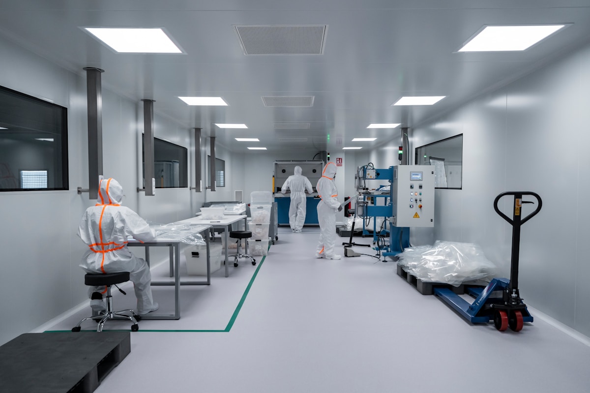
Proper spatial separation between cleanrooms and manufacturing operations prevents vibration-induced contamination, reduces cross-contamination risks, and ensures HVAC efficiency is maintained.
Vibration Sensitivity and Equipment Proximity
Locating modular cleanrooms near heavy manufacturing equipment or loading docks introduces vibration risks that can compromise cleanroom integrity. Constant mechanical shock and vibration from forklifts, conveyor systems, or industrial machinery can induce particle release from surfaces, damage HEPA filter seals, and cause micro-leaks in ductwork connections.
Vibration transmission through flooring and structural connections is a critical concern for ISO Class 5 and below environments. Even low-frequency vibrations from nearby loading dock operations can disrupt laminar airflow patterns and increase particle counts beyond acceptable thresholds.
Contamination Control Buffer Zones
Anterooms and buffer zones serve as transitional spaces that reduce particle transfer between cleanroom areas and manufacturing operations. These buffer zones create pressure differentials that prevent contaminated air from manufacturing areas from entering the cleanroom environment.
The effectiveness of buffer zones depends on proper placement relative to manufacturing operations. When cleanrooms are positioned too close to production areas, buffer zones may become inadequate barriers against contamination. Strategic distance assessment ensures that buffer zones function as designed, maintaining the required pressure cascades.
- Buffer Zone Width: Minimum 2-3 meter wide transitional spaces between cleanroom and manufacturing areas, providing adequate space for airlocks and personnel gowning.
- Pressure Differential: Buffer zones should maintain 10-15 Pa positive pressure relative to manufacturing areas to prevent contamination ingress.
- Material Transfer: Dedicated pass-through hatches with interlocking doors should be positioned away from direct manufacturing airflow paths.
Workflow Efficiency and Material Transfer Routes
Optimal cleanroom placement balances contamination control with operational efficiency. Material transfer routes between manufacturing operations and cleanroom areas should be direct yet isolated to prevent cross-contamination. Excessive distance increases handling time and potential contamination events, while insufficient separation compromises environmental control.
Freestanding modular cleanrooms offer flexibility in placement relative to existing manufacturing operations. These structures can be positioned to optimize material flow while maintaining required separation distances. Built-in cleanroom configurations within existing facilities require careful assessment of structural constraints and existing workflow patterns.
HVAC Integration and Airflow Pattern Considerations
HVAC system placement and airflow patterns must account for proximity to manufacturing operations. External air intake locations should be positioned upwind of manufacturing emission sources and loading dock areas. Contaminated air from production operations should never be drawn into cleanroom HVAC systems.
ISO classification requirements influence placement decisions. Higher classification cleanrooms (ISO Class 5 and below) require greater separation from contamination sources compared to lower classification areas. The cleanroom layout must ensure that airflow patterns move from clean areas toward manufacturing zones, never in reverse.
Loading Dock Contamination Risk Assessment
Loading dock proximity presents unique contamination challenges for cleanroom placement. Dock operations generate significant particulate matter from packaging materials, vehicle exhaust, and external air introduction. Wind patterns around loading areas can carry contaminants toward cleanroom intake vents.
When evaluating cleanroom placement near loading facilities, consider seasonal wind patterns, dock door frequency, and material handling equipment routes. Loading dock contamination risk increases exponentially when cleanrooms are positioned within the direct path of dock door airflow or vehicle traffic patterns.
- Dock Separation: Position cleanrooms at least 30 meters from loading dock doors when possible, accounting for prevailing wind direction.
- Air Intake Placement: Locate cleanroom HVAC intakes on the opposite side of the building from loading operations, with adequate screening and filtration.
- Vehicle Traffic: Establish designated material transport routes that separate cleanroom personnel flows from loading dock vehicle traffic.
Check Utilities and Structural Requirements
Successful cleanroom installation hinges on verifying that the host building can support the system’s structural loads and that all utility infrastructure is adequately sized and accessible for integration.
Structural Load Considerations in Existing Buildings
The single most common bottleneck for retrofitting modular cleanrooms into existing facilities is insufficient floor load capacity. Traditional cleanroom approaches, which rely on heavy steel framing, bulky ductwork, and solid wall systems, can impose dead loads that exceed the design parameters of older industrial or commercial structures. This often forces difficult choices between costly structural reinforcement or abandoning the project entirely.
This is where advanced lightweight composite panel systems provide a decisive engineering advantage. By utilizing high-strength facings combined with engineered foam or honeycomb cores, these panels deliver exceptional rigidity and load-bearing performance at a fraction of the weight of conventional materials. This dramatic reduction in dead load allows for the installation of ISO-certified cleanrooms in buildings that were previously deemed unsuitable, preserving ceiling height and eliminating the need for expensive foundation upgrades.
Utility Integration and Accessibility
Beyond structural integrity, the availability and capacity of building utilities are non-negotiable prerequisites. HVAC systems must be evaluated not just for cooling capacity, but for their ability to handle the significant static pressure drop introduced by HEPA/ULPA filter banks and the rigorous air change rates required for higher ISO classifications. Existing electrical systems need dedicated, clean power circuits with sufficient spare capacity to support the continuous operation of air handling units, lighting, and process equipment without overloading the facility’s main distribution panel.
Plumbing and compressed gas lines require equal scrutiny. For pharmaceutical or semiconductor applications, the integration of cleanroom-grade stainless steel piping for process gases and ultra-pure water must be planned before wall closure. Modular designs excel here by offering flexible service chase options and pre-fabricated penetrations, allowing technicians to route utilities through the ceiling plenum or wall cavities with minimal disruption to ongoing building operations.
Site Selection for Minimal Contamination Risk
The physical placement of the cleanroom within the facility directly impacts its ability to maintain class compliance. Locations adjacent to loading docks, exhaust vents, or high-traffic corridors introduce uncontrolled particulate and contaminant loads that can overwhelm filtration systems. A thorough site evaluation must identify and avoid these sources of cross-contamination, prioritizing areas with stable environmental conditions and minimal vibration from heavy machinery or loading activities.
Furthermore, the cleanroom’s position should facilitate a logical personnel and material flow. Placing the suite too close to raw material storage or waste removal paths can compromise the pressure cascade, allowing contaminated air to flow from less-clean to more-clean zones. Strategic placement, often enabled by the flexible footprint of modular systems, ensures that airlocks and pass-throughs function as intended, maintaining the critical pressure differentials that define a controlled environment.
Balancing Structural Constraints with Functional Needs
Ultimately, checking utilities and structural requirements is an exercise in balancing constraints with functionality. The ideal location must satisfy a matrix of competing demands: adequate floor loading, sufficient ceiling height for ductwork and maintenance access, proximity to utility risers, and isolation from contamination sources. When these factors align, the result is a cleanroom installation that is not only compliant with ISO standards but also efficient to operate and maintain.
Always request a structural load calculation from your cleanroom provider that accounts for the total dead load of the panel system, live load of personnel and equipment, and the point loads from any suspended ceilings or overhead utilities. This document is essential for securing approval from building engineers and ensuring long-term structural safety.
Assuming that existing building utilities are sufficient without professional verification is a costly error. Undersized HVAC or electrical circuits can lead to cleanroom failure to meet certification standards, resulting in project delays and expensive retrofits after installation has begun.
| Utility/Requirement | Specification | Benefit |
|---|---|---|
| Structural Load Capacity | Minimum 150 psf floor loading; ceiling grid supports 25+ psf | Ensures stability for heavy HVAC equipment, cleanroom panels, and overhead utilities |
| Ceiling Height Clearance | Minimum 9-12 ft clear height; 14+ ft for ISO 5-6 laminar flow | Accommodates ductwork, HEPA/ULPA filters, and proper air distribution without obstruction |
| HVAC & Air Changes | ISO 7: 20-40 ACH; ISO 5: 240-360 ACH (laminar, 0.45 m/s ±20%) | Maintains required particle counts and prevents contaminant accumulation |
| Electrical Supply | Dedicated 208/480V 3-phase circuits; 15-20% spare capacity for expansion | Supports HVAC, lighting, and process equipment with reliability and future scalability |
| Air Intake Placement | Strategic placement of outdoor air intakes away from contamination sources like loading docks and exhaust vents directly reduces the particulate burden on filtration systems. Since cleanrooms located near loading docks, highways, or manufacturing facilities face increased filter replacement demands due to higher particulate loads, proper intake location minimizes contamination loads on filtration systems. | Minimizes contamination loads |
| Plumbing & Gas Lines | Cleanroom-grade stainless steel; dedicated supply/return with leak detection | Ensures safe delivery of process gases, DI water, and utilities without contamination risk |
| Temperature & Humidity Control | Temp: 68-72°F ±2°F; RH: 40-60% ±5% (process-dependent) | Maintains operator comfort, material stability, and electrostatic discharge control |
| Pressure Differential | Minimum 0.02-0.05 in. w.g. between adjacent zones; cascade pressure grading | Prevents cross-contamination by directing airflow from clean to less-clean areas |
| Emergency & Safety Systems | NFPA-compliant fire suppression; Backup power with ≥10 min runtime | Ensures personnel safety and protects critical processes during power or emergency events |
Verify Zoning and Regulatory Compliance
Executive Summary: Verifying zoning involves ensuring the site’s existing occupancy classification supports the cleanroom’s intended use and that the design strictly adheres to specific GMP grades (A-D) and ISO standards (5-8) to avoid regulatory failure.
The most critical risk in retrofitting a cleanroom into an existing facility is the conflict between the building’s original “Occupancy Group” and the cleanroom’s operational requirements. If the selected site is zoned for general office or storage (Group B or S) but the intended use involves hazardous chemicals or high-risk biological processes (Group H), the project will face immediate regulatory stoppage. Compliance is not merely about cleanliness; it is fundamentally about adhering to local building codes, fire safety regulations, and industry-specific GMP (Good Manufacturing Practice) standards that dictate the physical layout and material allowances of the space.
Occupancy Classification and Building Codes
Before installation, the facility must undergo a rigorous zoning verification against local building codes (such as the IBC or local equivalents). A modular cleanroom often changes the hazard profile of the existing area. For instance, introducing significant quantities of flammable solvents or volatile organic compounds (VOCs) may reclassify the area as a “High-Hazard” occupancy, triggering strict requirements for explosion-proof electrical systems, fire-rated walls, and specialized ventilation. Failing to align the site selection with these occupancy classifications can result in costly retrofitting of the building’s infrastructure, such as upgrading sprinkler systems or expanding egress routes to handle higher occupant loads during shift changes.
GMP Zoning and ISO Classification Standards
In regulated industries like pharmaceuticals and biotechnology, zoning is dictated by the required cleanliness level. It is imperative to map the specific process requirements to the correct GMP Grade (A to D) and ISO Class (5 to 8) as defined in ISO 14644-1 and EU GMP guidelines. The selected site must be capable of supporting the airflow cascades and pressure differentials required for these classifications without violating the building’s physical constraints.
| GMP Grade | Equivalent ISO Class | Typical Application |
|---|---|---|
| Grade A | ISO 5 | Aseptic filling/processing zone (high risk) |
| Grade B | ISO 5 (at rest) | Background for Grade A (aseptic prep) |
| Grade C | ISO 7 / ISO 8 | Less critical stages (primary packaging) |
| Grade D | ISO 8 | Supporting operations (handling raw materials) |
The site must accommodate the necessary buffer zones and airlocks to maintain these gradients. If the existing floor plan is too cramped to install the required cascading pressure airlocks (e.g., a “bubble” schematic for sterile products), the site is non-compliant regardless of the filtration technology used. Furthermore, regulatory bodies like the FDA require documented evidence that the environment is suitable for the intended process; a site that cannot physically sustain these environmental controls will fail validation.
Material Compliance and Fire Safety Regulations
The materials used for the cleanroom envelope (walls, ceilings, and floors) must meet specific fire safety ratings and low-outgassing standards. Regulatory bodies often require materials to achieve specific flame spread and smoke developed indices (e.g., Class 1 or Class A per ASTM E84). When verifying zoning, confirm that the chosen composite panel materials—whether using aluminum, steel, or fiberglass skins with cores like PU, PIR, or mineral wool—comply with the local fire code for the specific occupancy type. Using non-compliant core materials in a regulated area can lead to the rejection of the entire facility certification, regardless of operational cleanliness.
📋 Regulatory Verification Checklist
- Step 1: Consult local building authorities to determine if the proposed cleanroom use changes the building’s Occupancy Group.
- Step 2: Map the process flow to GMP Grades (A-D) and verify the site geometry supports required airlocks/pressure cascades.
- Step 3: Verify panel material fire ratings (ASTM E84 or equivalent) against local fire code requirements for the specific zone.
- Step 4: Cross-reference HVAC integration points to ensure they meet FDA or EMA guidelines for air change rates and filtration.
Prepare the Site for Commissioning
Site preparation is the bridge between planning and a cleanroom that passes validation on the first attempt. Skip it, and you will fight leaks, contamination, and certification failures.
Verifying Sub-Floor Flatness and Levelness
Modular cleanroom panels connect through precision interlocking joints. When the sub-floor deviates from level, those joints cannot seal properly. The result is micro-gaps that become direct pathways for unfiltered air infiltration. This is one of the most common causes of failed HEPA leak tests during commissioning.
We recommend a maximum deviation of 3 millimeters over any 3-meter span for ISO Class 7 and above. For ISO Class 5 or stricter environments, the threshold tightens to 2 millimeters over the same distance. Our engineering team measures sub-floor flatness using a digital inclinometer and a straightedge calibrated to ISO 10136 standards before any panel delivery arrives on site.
- Tolerance for ISO 7: 3mm deviation per 3-meter span maximum
- Tolerance for ISO 5–6: 2mm deviation per 3-meter span maximum
- Measurement tool: Digital inclinometer with 0.1-degree resolution
- Corrective action: Self-leveling underlayment or shimming at panel support points
Many contractors assume a concrete slab is flat enough after curing. It rarely is. We have seen projects where a 12mm deviation across a 6-meter run caused panel warping, compromised sealant adhesion, and required complete disassembly and re-leveling — adding 5 to 7 days to the schedule and $8,000 to $15,000 in rework costs.
Sealing Existing Utility Penetrations and Joints
Existing buildings contain dozens of uncontrolled air pathways. Floor drain covers, conduit penetrations, wall-to-floor joints, and HVAC duct seams all act as contaminant sources. A modular cleanroom is only as airtight as the envelope it sits within. If outside air can bleed through unsealed penetrations, the cleanroom HVAC system will fight a losing battle to maintain pressure differentials.
Before panel installation begins, every penetration within the cleanroom boundary and the adjacent buffer zone must be sealed. We use UL 181-rated mastic for duct seams, polyurethane-based sealant for wall-to-floor joints, and gasketed cover plates for conduit entries. In our experience retrofitting existing facilities, approximately 40 to 60 percent of failed pressure decay tests trace back to improperly sealed existing penetrations rather than the modular panels themselves.
- Wall-to-floor joints: Seal with flexible polyurethane caulk rated for 25 percent movement capability
- Conduit and pipe penetrations: Use listed grommet assemblies with compression fittings
- Floor drain openings: Install airtight removable covers rated for the intended pressure class
- Existing HVAC duct seams: Apply UL 181 mastic tape or liquid-applied sealant
- Expansion joints: Bridge with flexible sealant that maintains continuity under thermal cycling
When retrofitting into an occupied building, perform a smoke test at every penetration before sealing. If smoke is drawn inward at any point, that is an air leak that must be addressed before the cleanroom envelope is closed. A $20 smoke tube and 30 minutes of testing can prevent a $50,000 rework later.
Implementing Rigorous Pre-Construction Cleaning Protocols
Construction sites generate enormous quantities of particulate matter. Drywall sanding, concrete grinding, cutting, and general material handling all deposit dust on surfaces that will become cleanroom floors and walls. If that dust is not removed before panel installation begins, it becomes permanently trapped beneath the cleanroom floor and inside wall cavities — where it will continuously resuspend during operation.
Our standard protocol requires a three-stage cleaning process before any modular panel touches the floor. First, a commercial HEPA-filtered vacuum removes all loose debris. Second, a damp-wipe cycle with a lint-free cloth and neutral pH cleaner captures residual dust. Third, a final HEPA vacuum pass verifies surface cleanliness using particle counting at representative sampling points. We typically target a baseline of fewer than 352,000 particles per cubic meter at 0.5 micrometers before panel installation commences.
- Stage 1 — Dry removal: HEPA vacuum all floor and wall surfaces to remove loose particulate
- Stage 2 — Wet cleaning: Damp-wipe with lint-free cloths and neutral pH cleaner
- Stage 3 — Verification: HEPA vacuum pass with particle count validation at sample points
- Target baseline: Under 352,000 particles/m³ at 0.5 micrometers before panel installation
Establishing Controlled Material Storage Zones
Composite panels, sealants, gaskets, and filtration components are all sensitive to contamination during storage. Exposing them to an active construction environment introduces dust, moisture, and physical damage risks before they are even installed. A dedicated material staging area within the cleanroom boundary — or immediately adjacent to it — is essential for maintaining component integrity.
The storage zone must be enclosed, climate-controlled, and kept under positive pressure relative to the surrounding construction area. Panels should remain in their factory packaging until the moment of installation. Our team at Rax Panel ships panels with protective film on both faces and polyethylene end caps to prevent edge damage during handling. Once the packaging is removed on site, panels must be installed within 48 hours to avoid surface contamination that would require re-cleaning before commissioning.
- Enclosure: Temporary walls or plastic sheeting to isolate the storage zone from construction activity
- Climate control: Maintain temperature between 15°C and 30°C with relative humidity below 60 percent
- Positive pressure: Maintain 5 to 10 Pascals above the surrounding construction area
- Packaging integrity: Keep factory protective film and end caps on until installation
- Installation window: Unwrap and install panels within 48 hours to prevent contamination buildup
📋 Actionable Steps
- Step 1: Measure sub-floor flatness with a calibrated straightedge and digital inclinometer. Document deviations and correct with self-leveling underlayment if tolerance exceeds 3mm per 3m span.
- Step 2: Conduct a smoke test on all existing penetrations. Seal every leak point with appropriate sealants and gasketed fittings before any panel delivery.
- Step 3: Execute the three-stage cleaning protocol. Verify particle baseline with an authorized particle counter before authorizing panel installation.
- Step 4: Establish an enclosed, positively pressurized material storage zone. Keep all panels in factory packaging until installation and schedule delivery to match the 48-hour unwrap-and-install window.
- Step 5: Perform a final pre-installation walkthrough with your Rax Panel project engineer to confirm all site conditions meet the readiness checklist before production panels arrive.
Conclusion
Getting the site evaluation right determines everything else for the build. You might prioritize layout aesthetics, but if the structural load or utility access fails, the ISO classification won’t hold up. We’ve seen expensive projects stall because external vibration sources or airflow proximity wasn’t mapped early. Don’t guess on the sub-floor flatness. Uneven floors ruin your pressurization strategy instantly. The building’s existing envelope dictates your performance more than the fan filters do.
- Verify structural load capacity before finalizing any coordinates.
- Map existing HVAC routing to prevent future contamination conflicts.
- Rigorously seal all existing utility penetrations to stop particulate bypass.
- Use our engineering team as a technical backup for your specific layout logic.
Frequently Asked Questions
Can existing rooms be retrofitted?
Existing spaces can often be converted into cleanrooms if the floor is level and the structure meets specific load and airtightness requirements. Retrofitting is a cost-effective strategy compared to new construction, provided utility access is feasible. However, strict validation of the existing envelope is necessary to ensure it meets modern ISO standards.
Can the site support future expansion?
Selecting a location with adjacent vacant space allows for modular expansion without disrupting current cleanroom operations. Future-proofing the site saves significant relocation costs and downtime as production scales. It is crucial to verify that the existing utility infrastructure can handle the increased load of a larger facility.
Why is ceiling height critical?
Adequate ceiling height is essential to accommodate the complex ductwork, HEPA filter housings, and lighting systems required for air recirculation. Insufficient vertical space restricts airflow patterns, potentially creating dead zones that compromise cleanliness. We generally recommend a minimum height clearance to ensure laminar flow reaches the work surface effectively.
Does vibration impact cleanroom performance?
Yes, excessive vibration from nearby heavy machinery or railways can disrupt sensitive equipment and compromise particle containment. You must isolate the cleanroom from vibration sources to maintain operational integrity and classification standards. Specialized mounts or structural isolation layers are often required in high-vibration zones.
Are emergency exits easily accessible?
Emergency egress routes must be direct, unobstructed, and lead to a safe area without compromising the cleanroom’s controlled environment. The location must allow for easy exit access even while personnel are wearing restrictive protective clothing. Compliance with local fire safety codes is non-negotiable for the safety of your workforce.
How to minimize installation leakage risks?
Ensuring airtight seals at panel junctions and utility penetrations is critical to passing integrity testing and maintaining pressure differentials. Choosing prefabricated modular panels with precision-machined connection details drastically reduces the risk of human error during assembly. Rax Panel’s manufacturing precision ensures tight tolerances that facilitate a leak-free installation environment.