
A proficient crew installs 600 square meters of sandwich panels in a single 8-hour shift. That speed is why commercial projects spec these systems. But sandwich panel installation only delivers real value when every joint seals tight and every fastener lands at the correct torque. One over-driven screw, one misaligned joint, or one skipped sealant line turns a fast build into a rework cycle. U.S. DOE testing confirms that air leakage accounts for up to 40% of heat loss in commercial buildings. Your panel joints are the primary defense.
This guide covers wall and roof mounting procedures step by step, from subframe tolerance verification through final weatherproofing. We walk through the failure modes that trigger code rejection: thermal bridging at attachment points, insufficient roof pitch causing water ponding, and joint seal gaps that push your air leakage rate past the ACH50 target. You get fastener spacing tables, torque specs, and material handling protocols that keep your zero-defect inspection rate intact from delivery through sign-off.
What Are Sandwich Panels and Why Install Method Matters
A sandwich panel‘s thermal performance is only as good as its installation. Misaligned joints and inadequate sealing can destroy up to 40% of a building’s thermal efficiency regardless of the core material specified.
Sandwich Panel Structure: The Skin-Core-Skin Architecture
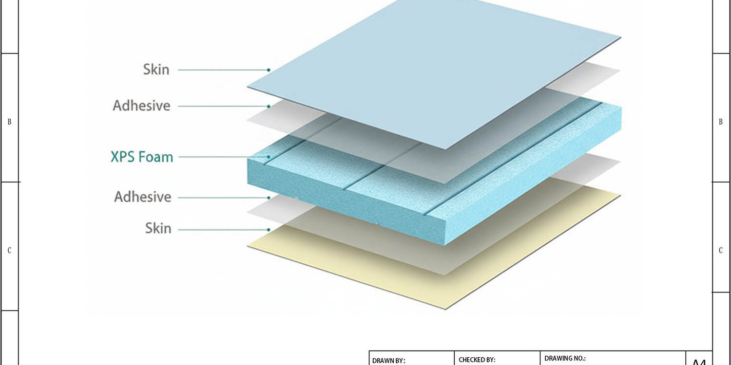
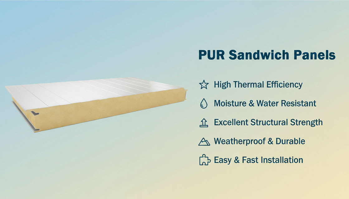
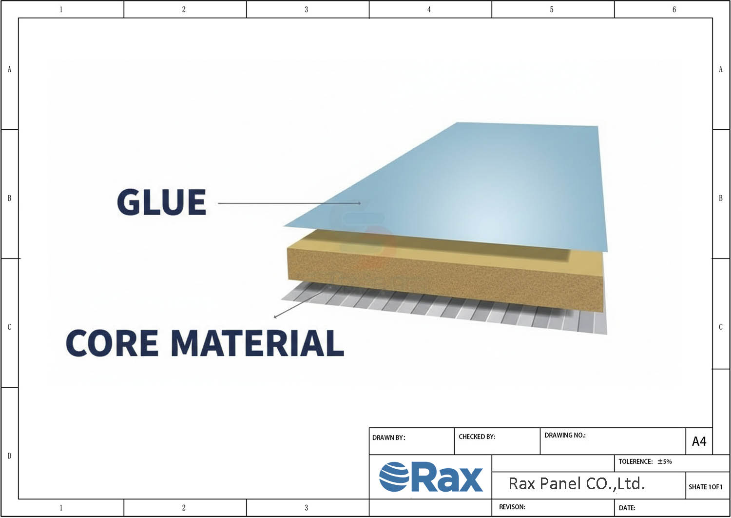
A sandwich panel is a three-layer composite assembly. Two rigid facing skins, typically GRP/FRP, aluminum, steel, or CFRT, are bonded to a lightweight insulating core. The core material carries the thermal load; the skins carry the structural and weatherproofing load. Together, they function as a single structural unit that is significantly stronger per kilogram than any individual component acting alone.
The core options available for industrial and commercial applications span a wide thermal conductivity range. PU and PIR cores operate at 0.022–0.028 W/mK, making them the standard choice for cold rooms and temperature-controlled facilities.
EPS cores sit higher at 0.034–0.038 W/mK, suitable for standard warehouse and modular building envelopes where extreme thermal performance is not the primary driver. Mineral wool cores sacrifice some thermal efficiency but deliver Class A fire ratings required by code in many industrial and public assembly occupancies.
Panel thickness ranges from 50mm to 250mm for wall applications and 75mm to 200mm for roof assemblies. The critical point for project planners: R-value is a material property, but whole-wall R-value is a system property. The difference between the two is determined entirely by what happens at the joints during installation.
How Installation Determines Real-World R-Value and Airtightness
Manufacturers certify panel R-values based on the insulated core alone. That number is a best-case scenario. In the field, thermal bridges at fastener points, unsealed joints, and compression gaps at panel-to-structural connections all degrade the rated performance.
Oak Ridge National Laboratory testing demonstrated this gap clearly: a 3.5-inch SIP wall achieves a whole-wall R-value of 14.09, while a conventional 2×4 stick-framed wall with cavity insulation only reaches 9.58, a 47% improvement. But that 14.09 figure assumes correct joint sealing and proper fastener installation. Poorly sealed panel joints can bring the actual whole-wall R-value back down toward stick-frame levels.
Air leakage accounts for up to 40% of total heat loss in commercial buildings, according to U.S. Department of Energy testing data. The panel itself does not leak air; the joints between panels and the penetrations through them do. This is why the installation method and crew competency directly control whether a building achieves its designed energy performance or falls short by a wide margin.
Joint Sealing: The 15x Airtightness Factor
U.S. DOE testing has shown that properly installed panel structures can be up to 15 times more airtight than traditional stick-framed construction. That statistic is not a material property. It is an installation outcome. It requires continuous sealing at every panel-to-panel joint, every panel-to-structure connection, and every penetration point. Miss one joint, and the airtightness advantage collapses at that location, creating a localized thermal leak that drives condensation risk and energy loss.
Joint sealing systems for industrial sandwich panels typically combine three components working in sequence: expanding foam strips compressed within the panel joint profile, butyl tape applied to the metal-to-metal contact surfaces, and polyurethane sealant gunned into the external joint reveal.
Each layer serves a different function: the foam provides bulk air blockage, the butyl tape handles moisture ingress at the skin interface, and the PU sealant protects against wind-driven rain. Skipping any one of these layers is the most common installation failure our engineering team encounters during project audits.
Building Code Compliance: Performance Depends on Execution
Energy codes across most jurisdictions now mandate maximum air leakage rates, minimum whole-wall R-values, and specific fire performance classes. The panel material alone does not satisfy these requirements. The installed assembly does. A PU-core panel rated at 0.022 W/mK will not pass a blower door test if the installation crew failed to maintain the ±2mm base leveling tolerance before fastening the first panel.
Misalignment accumulates across the building envelope. By the time you reach the fifth or sixth panel in a run, a 2mm error at the base can translate into a 10mm gap at the top, far beyond what the sealing system can compensate for.
Fire ratings follow the same logic. A mineral wool core panel achieves Class A fire performance in the lab, but if the joint profile is not correctly engaged during installation and leaves a direct path for flame spread through the joint cavity, the field performance will not match the certification. Code inspectors evaluate the installed condition, not the product data sheet.
This is why Rax Panel provides joint detailing drawings and installation guidance specific to each panel configuration, not generic instructions. The specific facing material (GRP versus aluminum versus steel) and core type (PU versus PET versus PP honeycomb) each require different sealant chemistries, fastener types, and joint engagement procedures to maintain rated performance.
Wall Panel Installation: Step-by-Step Methods
Wall panel installation fails at the joints, not the panel surface. Subframe tolerance, fastener selection, and sealant execution determine whether a wall assembly achieves its rated thermal performance or becomes a 40% energy penalty.
Subframe and Base Preparation
Before any panel leaves the ground, verify the supporting subframe. Steel or timber framing must be checked for plumb, level, and alignment across the full wall plane. The accepted tolerance for base rail leveling is ±2mm over any 3-meter span. Exceeding this tolerance creates uneven compression at panel joints, which forces gaps open under thermal cycling and destroys the airtight seal the system was designed to achieve.
Place a moisture barrier, typically a self-adhesive bituminous membrane or EPDM-based sill tape, along the full length of the base rail before setting the first panel course. This barrier prevents capillary moisture from wicking into the panel core through the bottom edge. On concrete plinths, verify that the concrete is fully cured and surface-dry before applying any membrane. Trapped moisture behind the barrier will degrade PU and XPS foam cores over time.
For Rax Panel’s GRP/FRP wall panels with PU or XPS cores (50mm–250mm thickness range, 1000mm–1200mm standard width), the subframe girt spacing must match the fastener calculation from your project engineer. Typical girt spacing for wall panels spans 1.2m to 1.5m depending on design wind load. Do not guess this spacing: over-spanning causes panel deflection visible within months; under-spanning wastes steel and labor.
Fastening Systems: Exposed vs. Concealed
Choosing between exposed and concealed fastening is a lifecycle cost decision, not just an aesthetic preference. Each system carries distinct tradeoffs that affect installation speed, thermal performance, and long-term maintenance exposure.
- Exposed Fastening: Self-tapping screws with EPDM washers, driven at 4–6 Nm torque. Installation is straightforward: crew productivity averages 20–30% faster than concealed systems. The EPDM washer compresses against the panel facing to create the primary water seal. Drawback: each fastener creates a thermal bridge through the panel cross-section, and washer degradation over 15–20 years requires inspection and possible replacement.
- Concealed Fastening: Clips or brackets engage into the panel side joint, hidden from the exterior face. Eliminates thermal bridging at attachment points and produces a clean facade. Drawback: installation speed drops 20–30% compared to exposed systems because clip alignment must be precise. The labor cost increase is real, but the energy savings from eliminated thermal bridges often offset it within 5–7 years on temperature-controlled buildings.
Calculate the tradeoff honestly. If you are cladding a cold room operating at -20°C with PU-core panels (thermal conductivity 0.022–0.028 W/mK), concealed fastening pays for itself fast. Every exposed fastener at that temperature differential becomes a localized condensation point. For a standard unheated warehouse, the energy penalty from exposed fasteners is negligible, and the faster install saves real budget.
Panel Joint Sealing for Thermal Performance
Air leakage accounts for up to 40% of heat loss in buildings, per U.S. DOE testing. The panel joint is your primary, and often only, defense. Get the seal wrong, and the rated R-value of your wall assembly becomes theoretical rather than actual. Three sealing materials handle the workload:
- Butyl Tape: Applied to the panel tongue or groove before joint engagement. Provides a pre-compressed, immediately effective seal. Best for standard wall panel joints where the profile allows tape placement on a flat surface. Pressure-sensitive: requires firm, even compression during panel mating.
- PU Sealant (Polyurethane): Gun-applied into the joint cavity after panel placement. Used as a secondary seal or where joint geometry prevents tape adhesion. Requires surface preparation: dust, oil, or moisture on the joint face will cause adhesion failure. Cure time is 24–48 hours depending on temperature and humidity.
- EPDM Gaskets: Pre-formed profiles that seat into the joint channel. Common in cold room and controlled-environment installations where the joint must accommodate repeated thermal cycling without losing compression. More expensive than tape, but resists degradation at temperature extremes better than butyl.
Run the seal continuously. A 10mm gap in a 6-meter joint seal renders the entire joint ineffective. At corners and intersections, overlap tape or sealant by at least 30mm. Never butt-join sealing materials. For GRP/FRP panels with PU foam cores in cold room applications, we recommend a dual-seal strategy: butyl tape as the primary barrier with PU sealant applied to the interior joint face as a secondary line of defense.
Corner and Edge Detailing
Corners, window reveals, and penetrations are where water ingress actually happens in the field. The flat panel field rarely leaks if joints are sealed correctly. Corners leak because flashing geometry creates opposing water paths, and penetrations leak because the seal between a round pipe and a flat panel is inherently difficult.
Install corner flashing before the final panel on each wall plane. The flashing must lap over the first panel’s edge by at least 50mm and extend behind the second panel’s facing.
Seal the top edge of the flashing to the panel facing with PU sealant. Never rely on mechanical pressure alone to hold a vertical water seal. At external corners on insulated walls, consider inserting a thermal break strip behind the flashing to prevent the corner from becoming a thermal bridge between interior and exterior faces.
Penetrations, such as conduit, pipe runs, and structural brackets, require a two-stage seal. Apply a backing rod or closed-cell foam ring around the penetration to fill the bulk of the gap. Then gun PU sealant over the backing rod to create the weatherproof face. Do not stuff open-cell foam or mineral wool into a penetration gap and call it sealed. Those materials are air-permeable and will allow moisture migration into the panel core over time.
Window and door reveals follow the same principle: continuous seal, lapped flashing, and thermal break where the reveal panel meets the primary wall panel. Rax Panel’s custom sizing capability allows you to order reveal panels cut to exact dimensions, which eliminates the field-cutting errors that cause misalignment and gap failures at these transitions. Measure twice, order once.
Roof Panel Installation: Techniques and Critical Factors
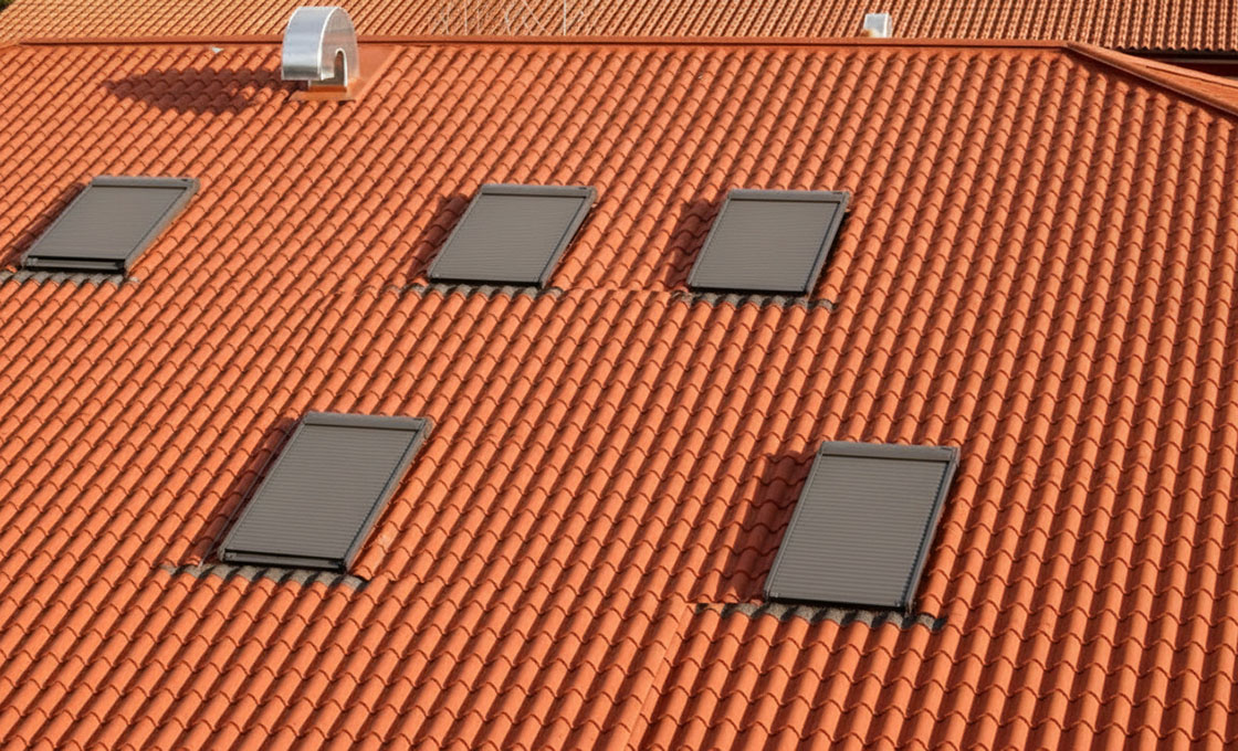
Roof panel failures account for the majority of sandwich panel warranty claims, not because of defective materials, but because installers ignore pitch minimums, skip thermal breaks at roof-to-wall transitions, and guess at fastener spacing instead of following calculated uplift tables.
Roof Pitch and Drainage Requirements
Water infiltration on sandwich panel roofs is almost always a pitch problem, not a material problem. Each panel profile has a hard minimum slope below which capillary action pulls water back up under the side laps. Get this wrong, and no amount of sealant will save the assembly.
Standing seam profiles, commonly used with aluminum-faced sandwich panels and GRP/FRP panels for industrial roofing, require a minimum pitch of 3° (approximately 5.2% slope). The trapezoidal ribs on these profiles provide some water channeling, but the seam relies on gravity to shed water.
Below 3°, standing water collects in the seams, degrades the sealant over time, and eventually finds its way through the joint. For Rax Panel’s aluminum sandwich panels with PU or PIR cores (thermal conductivity 0.022–0.028 W/mK), standing seam is the preferred profile for roof pitches between 3° and 15°.
Corrugated and trapezoidal through-fix profiles demand a steeper minimum pitch of 7° (approximately 12.3% slope). These profiles use exposed fasteners that penetrate the top face, creating potential entry points. At lower pitches, water travels along the screw shank instead of shedding over the corrugation. If your project specifies steel-faced or Aluzinc-faced foam core panels with a corrugated profile, verify the slope before panels leave the factory: retrofitting pitch on a completed roof frame is extremely expensive.
- Standing seam minimum pitch: 3° (5.2% slope), suitable for aluminum, GRP, and steel-faced panels with concealed fastener systems
- Corrugated profile minimum pitch: 7° (12.3% slope), required for through-fix panels with exposed fasteners
- Panel thickness range for roofs: 75mm–200mm depending on span and insulation requirements
- Standard roof panel width: 1000mm effective coverage after joint overlap
Drainage design must also account for panel end laps. On roofs exceeding standard panel lengths (typically 12 meters maximum), end laps introduce a second vulnerability point. Position end laps on purlins, seal both faces with butyl tape, and maintain minimum 200mm overlap.
In coastal or high-rainfall regions, increase overlap to 250mm and apply a continuous bead of PU sealant between the tape layers. Our engineering team at Rax Panel provides joint detailing drawings specific to your project’s wind zone and rainfall intensity during the design phase.
Roof-to-Wall Connection Details
The roof-to-wall junction is where most thermal bridges hide. It is also the detail most frequently botched on site, because it requires coordination between the roofing crew and the wall panel crew, two trades that often work on different schedules. The goal is continuous insulation with zero thermal gaps, which means the roof panel core must meet the wall panel core without interruption.
On standard industrial buildings, the roof panel typically bears on top of the wall panel or on a parapet flashing. The critical dimension is the gap between the roof panel bottom edge and the wall panel top edge.
If there is a steel purlin or eaves beam in this gap, that steel becomes a thermal bridge conducting heat directly through the envelope. The fix is a continuous thermal break, typically a 20mm minimum strip of closed-cell foam or a proprietary thermal spacer block, installed between the steel and the panel facing.
For cold room and controlled environment installations using GRP/FRP panels with PU foam cores, the roof-to-wall detail is even more critical. These facilities operate at internal temperatures of -25°C to +5°C, so any thermal bridge immediately shows up as condensation, frost, or ice formation.
The joint must be sealed with a continuous expanding seal strip on the warm side of the panel, then over-taped with aluminum foil tape, and finally protected with a preformed flashing on the external face. Skip any one of these three layers, and moisture will find its way in.
- Thermal break thickness: Minimum 20mm closed-cell foam or proprietary thermal spacer block at all steel-to-panel contact points
- Sealant sequence (cold rooms): Expanding seal strip (warm side) → aluminum foil tape → preformed metal flashing (external side)
- Eaves overhang minimum: 50mm to prevent capillary draw-back at the panel edge
Air leakage accounts for up to 40% of heat loss in buildings, and the roof-wall junction is a primary leakage path. U.S. Department of Energy testing has shown that properly sealed panel structures are up to 15 times more airtight than conventional stick framing. But that performance only materializes when every junction, including the eaves, is sealed to the manufacturer’s specification.
If you are targeting specific air leakage rates (ACH50) for code compliance, pressure-test the building before the eaves flashing goes on. It is far cheaper to fix a leak at the roof-wall junction when it is still accessible than after the flashing is riveted in place.
Weatherproofing and Wind Uplift Resistance
Wind uplift is the dominant structural load on roof panels. Negative pressure from wind flowing over the roof surface literally tries to peel panels off the purlins. The resistance comes entirely from the fastener system: specifically, the number of fasteners per square meter, the pull-out capacity of each fastener in the specific purlin gauge, and the integrity of the EPDM washer seal under cyclic loading.
Fastener torque is a parameter that must be controlled on site. For self-tapping screws with EPDM washers, the standard for steel and aluminum-faced sandwich panels, the target torque range is 4–6 Nm. Below 4 Nm, the EPDM washer does not compress enough to form a waterproof seal.
Above 6 Nm, the washer over-compresses and splits, or the screw head embeds into the panel facing, crushing the core and creating a localized soft spot that propagates into a dimple visible from inside the building. Use torque-controlled screwdrivers set to 5 Nm as the default, and verify with a torque wrench on the first 10 fasteners of each shift.
Fastener spacing depends on the wind zone, building height, and panel span. As a baseline for typical industrial buildings under 10 meters in eaves height in moderate wind zones:
- Field of roof (interior spans): 2 fasteners per purlin per panel width (approximately 1.1 fasteners per m² at standard purlin spacing)
- Roof edges (zone within 10% of roof width from gable): 3 fasteners per purlin per panel, a 50% increase over field spacing
- Corners (intersection of eaves and gable): 4 fasteners per purlin per panel, double the field spacing, as these zones experience the highest uplift coefficients per ASCE 7 and Eurocode 1
- Purlin contact: Minimum 40mm fastener penetration into supporting steel (adjust screw length for panel thickness + purlin flange + 40mm)
These are starting values, not final specifications. The project structural engineer must calculate actual uplift loads based on local wind speed data, terrain category, and building geometry. Rax Panel’s engineering team provides fastener schedules tailored to your specific panel configuration: whether you are using GRP/FRP foam core panels for a refrigerated truck roof, aluminum honeycomb panels for a modular building, or steel-faced PIR panels for an industrial warehouse.
The key point: never accept a generic fastener spacing from a catalog without verifying it against the project’s wind load calculation. The cost difference between 1.1 and 2.2 fasteners per square meter is trivial compared to the cost of a roof panel detachment event.
Concealed fastener systems (standing seam clips) offer a tradeoff that project managers should evaluate carefully. They eliminate the thermal bridge created by each screw penetration through the panel facing, which improves whole-roof R-value. However, concealed clip systems reduce installation speed by approximately 20–30% compared to exposed through-fix screws, because each clip must be precisely positioned and mechanically engaged.
For projects where lifecycle energy cost dominates the decision, such as cold storage, pharmaceutical facilities, or any building targeting net-zero energy, the energy savings from eliminating hundreds of thermal bridges typically justify the additional labor cost within 3–5 years of operation. For standard warehouse construction where heating energy is a minor operating cost, exposed fasteners with EPDM washers remain the pragmatic choice.
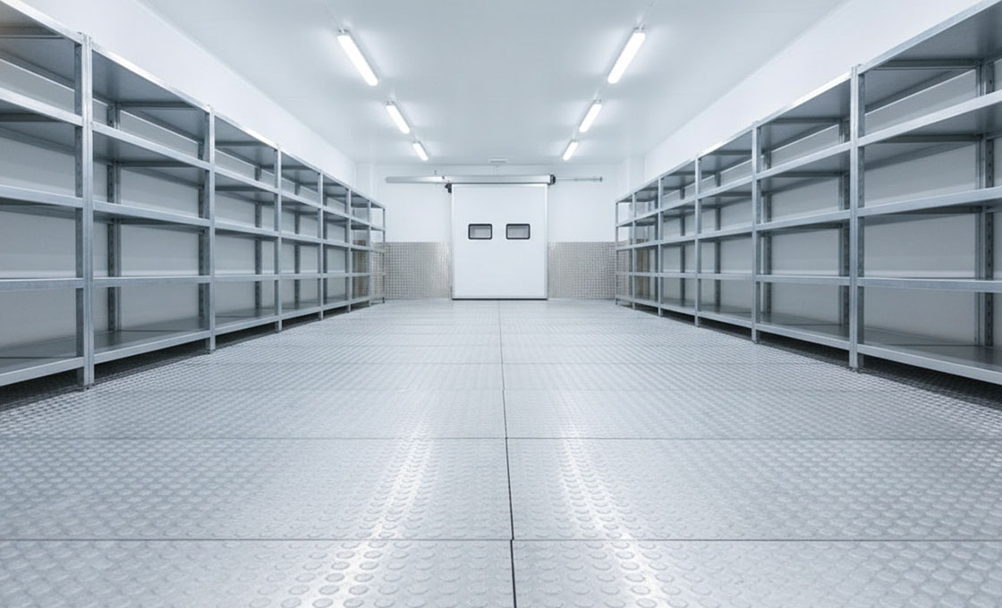
Cold Room and Controlled Environment Install
Cold room installations fail at the floor-wall junction more often than at any other point. Get the thermal break and vapor seal right at that intersection, and the rest of the envelope follows.
Floor and Wall Panel Integration
In controlled-environment builds such as cold storage, food processing, and pharmaceutical staging, the floor-to-wall transition is the single highest-risk detail in the entire envelope. Unlike standard commercial walls where a minor thermal leak just wastes energy, cold rooms operate at temperature differentials of 30°C to 50°C between interior and exterior. Any discontinuity at the base drives relentless condensation, frost heave, and eventual structural decay into the floor slab.
The integration starts before the first panel leaves the crate. Verify the concrete slab is level within a ±2mm tolerance across any 3-meter span. If the slab deviates beyond that, grind the high spots or fill the lows with a non-shrink grout before proceeding. Setting panels on an uneven base guarantees misaligned joints two courses up, guaranteed.
For cold room applications, GRP/FRP sandwich panels with PU foam cores (thermal conductivity 0.022–0.028 W/mK) are the standard specification at Rax Panel. The fiberglass facing is impermeable to moisture, dimensionally stable under thermal cycling, and resistant to the cleaning chemicals used in food and pharma hygiene protocols.
Set the wall panels into a continuous thermal break strip at the base, typically a closed-cell PE or EPDM profile rated for the panel load, rather than resting the panel steel or GRP edge directly on the slab. This detail alone prevents the most common thermal bridge in cold storage construction.
Vapor Barrier Continuity
Air leakage accounts for up to 40% of heat loss in buildings. In a cold room, that statistic inverts into a moisture-ingestion problem: warm, humid exterior air drawn through gaps condenses inside the panel core and saturates the insulation, destroying its R-value and breeding mold. Vapor barrier continuity is not a best-practice suggestion. It is the defining quality metric of the installation.
Maintain a continuous vapor seal on the warm side of the insulation at all times. On wall panels, this is typically the exterior facing in cold-storage scenarios. Every joint, every penetration, every corner must connect back to the vapor barrier of the adjacent panel without exception.
- Apply continuous butyl tape or expanding sealing strip in the panel tongue-and-groove joint before engaging the lock. Run the tape the full length of the panel. Never stop short by even 20mm at the ends, because that is exactly where the pressure differential pulls air through.
- Seal the floor-wall junction with a dedicated vapor barrier membrane that laps onto the wall panel facing by at least 50mm and ties into the slab vapor barrier beneath the floor insulation. This is a sequential process: slab barrier first, floor insulation second, wall panels third. Coordinate the trade schedule accordingly.
- Use compatible sealants only. Test the PU sealant or butyl tape against the panel facing material before full deployment. GRP facings with gelcoat surfaces bond differently than bare steel or aluminum. Ask Rax Panel’s engineering team for the approved sealant compatibility chart for your specific panel configuration.
After all panels are set and sealed, verify continuity with a blower door test or thermal imaging scan before the interior finishing trades cover the joints. Catching a vapor barrier gap during construction costs a fraction of what it costs to dismantle a finished cold room wall to fix one.
Specialized Jointing Systems for Hygiene
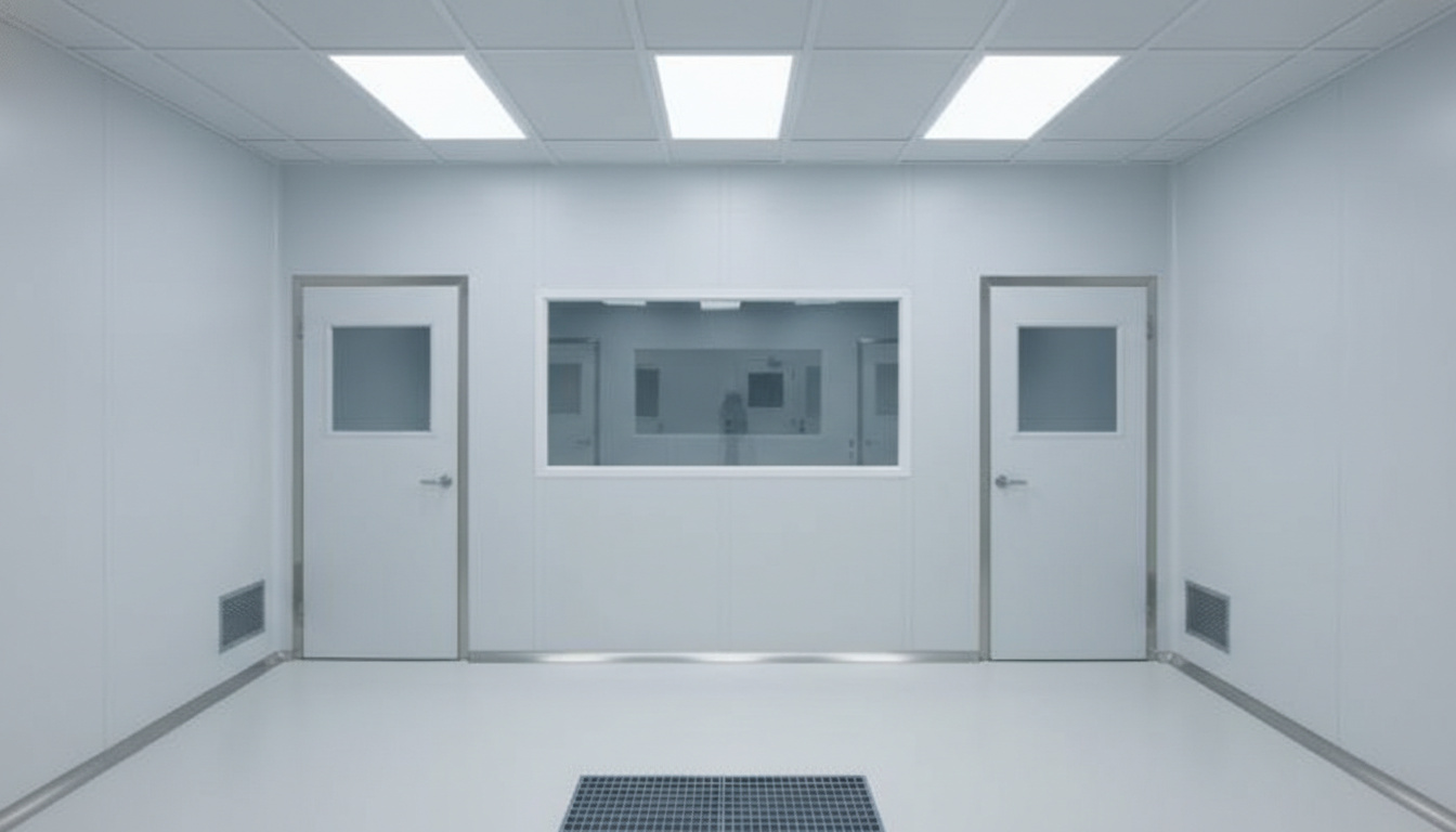
Standard tongue-and-groove panel joints with exposed fasteners are adequate for warehouses and general industrial enclosures. Cold rooms and hygiene-controlled environments demand more. The joint system must prevent moisture intrusion, eliminate crevices where bacteria can colonize, and allow disassembly for deep cleaning or panel replacement without destroying adjacent sections.
Cam-lock systems are the dominant solution. Panels are manufactured with embedded steel hooks and receivers in the panel edges. During installation, an Allen key inserted through a small hole in the facing rotates the cam, drawing the hook from the adjacent panel and pulling the joint tight under mechanical pressure. This achieves several things simultaneously:
- Uniform joint compression: The cam-lock applies consistent pressure along the entire joint length, compressing the sealing tape or gasket evenly. Hand-tightened or screw-tightened joints concentrate pressure at the fastener points and leave gaps between them.
- No through-fasteners in the panel field: Every screw that penetrates the panel facing is a potential thermal bridge and a potential leak point. Cam-locks eliminate the need for mechanical fasteners in the joint itself: panels are held by the lock mechanism and the structural frame attachment at the top and bottom.
- Flush interior surfaces: With no screw heads or rivet caps on the interior face, cleaning crews can sanitize the entire wall without navigating around hardware. This is a hard requirement in food-processing facilities governed by HACCP or equivalent hygiene standards.
Specify cam-lock jointing for all GRP/FRP and PU-core panels destined for cold rooms, clean rooms, and food-processing environments. When ordering from Rax Panel, confirm the cam-lock hardware specification with the engineering team: lock type, engagement depth, and torque rating vary with panel thickness (50mm–250mm range for walls). The factory can pre-install cam-lock hardware during production so the panels arrive site-ready, eliminating field-fit errors and accelerating assembly by a measurable margin over loose-supplied hardware kits.

Common Installation Failures and How to Avoid Them
Air leakage accounts for up to 40% of heat loss in buildings. In sandwich panel installations, four recurring failures are responsible for nearly all inspection rejections and post-occupancy thermal complaints: misaligned joints, incorrect torque, thermal bridging, and flashing leaks.
Misaligned Joints and Insufficient Sealant
Joint misalignment is the single most common cause of failed blower door tests on commercial panel projects. When panels sit out of plane by even 3–4mm, the sealant bond line becomes inconsistent. Butyl tape and PU sealant require a continuous, compressed contact surface to perform. A gap as small as 1.5mm at a joint allows capillary water draw and convective looping, destroying the whole-wall R-value you specified during procurement.
The root cause almost always traces back to subframe preparation. If your base leveling exceeds the ±2mm tolerance, every panel stacked above that point compounds the deviation. On a 6-meter wall run, a 2mm error at the base can translate to 8–10mm of cumulative misalignment at the top course. At that point, no amount of sealant compensates: the joint geometry is fundamentally compromised.
- Pre-installation check: Verify base frame level with a laser level at 1-meter intervals. Shim high spots; grind and re-weld low spots before any panel goes up.
- Sealant application sequence: Apply butyl tape to the male joint profile first, then run a continuous PU bead along the female profile before engaging the panels. Never rely on a single seal line.
- Panel engagement: Push panels together until the joint seats fully. If resistance exceeds normal levels, stop and inspect: the core may be protruding or the profile may be damaged from handling.
On GRP/FRP-skinned panels, the facing is less rigid than steel, so joint edges can flex under clamp pressure. Use temporary alignment clamps at 500mm intervals along the joint during fastening to prevent edge creep. Remove clamps only after all fasteners in that joint are torqued to spec.
Incorrect Fastener Torque
Self-tapping screws with EPDM washers require a torque range of 4–6 Nm. That range is narrow for a reason. Below 4 Nm, the EPDM washer does not compress enough to form a weatherproof seal against the panel facing. Above 6 Nm, the washer over-compresses and loses its elastic memory, creating a permanent cold flow path that will leak within 12 months. Over-torquing also dimples the panel skin, creating a visible defect that triggers inspection rejection on architectural facades.
We see this failure most often on aluminum-faced panels, where the thinner 0.6–0.7mm skin deforms under screw pressure far more easily than 1.0mm steel. The fix is procedural, not material: use torque-controlled drivers set to 5 Nm with a clutch disengagement, not standard impact drivers. Train crews to stop driving the moment the EPDM washer flattens to a uniform contact ring: no visible rubber should bulge beyond the washer edge.
- Concealed fastener systems: These eliminate exposed penetrations but reduce installation speed by 20–30%. Calculate whether the labor cost increase offsets the lifecycle energy gain from eliminating thermal bridges at attachment points.
- Fastener spacing: Follow project-specific engineering drawings, not generic guidelines. A rough benchmark is 1.1 fasteners per square meter for wall panels, but wind load zones, panel thickness, and core material all change the requirement.
- Edge distance: Maintain minimum 50mm from panel edges and end laps. Closer placement risks edge breakout, especially on PU and XPS foam cores.
Thermal Bridging at Penetrations
Every penetration through a sandwich panel, whether a pipe entry, cable tray, duct connection, or structural bracket, is a potential thermal short circuit. A steel bracket bolted through both skins of a PU core panel (thermal conductivity 0.022 W/mK) creates a direct conductive path that can reduce the local R-value by 60–70%. In cold room applications, these bridges show up as condensation streaks within weeks. In occupied buildings, they cause mold behind interior finishes months after handover.
The corrective approach is isolation. Use thermally broken brackets with nylon or fiberglass isolators between the bracket and the outer skin. For pipe penetrations, specify pre-insulated sleeve assemblies with integrated vapor barriers. Do not rely on site-applied foam and tape, which degrades within 2–3 years under thermal cycling.
Penetration seals must also maintain the air barrier continuity. Any gap around a penetration that allows air movement negates the panel system’s airtightness, which U.S. DOE testing shows can be 15 times tighter than stick framing when installed correctly.
On Rax Panel GRP/FRP panels, the fiberglass facing itself has lower thermal conductivity than steel or aluminum, which inherently reduces bridging severity at attachment points. But penetrations still require mechanical isolation. Do not assume the composite skin eliminates the problem. It reduces the problem without removing it.
Water Ingress at Flashing
Flashing is where 90% of roof-to-wall and ridge-hip junction failures occur. The failure mechanism is predictable: water gets driven behind the flashing by wind pressure, travels along the panel joint via capillary action, and saturates the core material at the joint edge. Once foam core absorbs moisture, its thermal conductivity increases, its dimensional stability drops, and in freezing climates, freeze-thaw cycling destroys the core-to-skin bond.
Flashing installation must follow a strict lapping sequence. Upper flashings always lap over lower flashings. End laps require a minimum 150mm overlap with a full bed of sealant between the layers. At roof-to-wall transitions, the wall panel flashing must integrate with the roof panel ridge flashing. Leaving a gap here is the most common single-point failure we see on inspection reports.
- Minimum roof pitch: 3° for standing seam profiles, 7° for corrugated profiles. Below these minimums, water ponds at flashings and eventually finds entry points regardless of sealant quality.
- Flashing material compatibility: Do not pair aluminum flashing with steel-faced panels without an isolation membrane. Galvanic corrosion at the contact point will perforate the flashing within 5 years in coastal or industrial environments.
- Inspection timing: Flashing should be checked immediately after installation and again before the roofing underlayer is closed. Once interior finishes cover the joint, leaks become diagnostic nightmares requiring thermal imaging to locate.
For cold room and controlled environment installations, flashing details are even more critical because any moisture inside the envelope affects humidity control and refrigeration energy consumption. Rax Panel engineers provide project-specific flashing details for GRP/FRP and aluminum-skinned panel systems as part of the custom solution package, because generic flashing details from steel-panel catalogs do not account for the different thermal expansion rates and joint geometries of composite panels.
Installation Tools and Equipment Checklist
Preparation at this stage determines the quality of everything that follows. Verify all dimensions against shop drawings, confirm substrate conditions, and stage materials in the order they’ll be needed.
Conclusion
Installation quality determines whether your sandwich panels hit their rated R-value or underperform by 40% due to air leakage at the joints. The thermal conductivity numbers on a datasheet mean nothing if your crew cuts corners on sealing, leveling, or fastener torque. That’s the reality of panel construction: materials are only as good as the hands that install them.
- Skipping base verification: If your subframe sits outside the ±2mm tolerance, every panel above it compounds the error. You’ll chase alignment issues across the entire elevation and waste labor hours on shims and filler strips.
- Overdriving fasteners: Torque beyond 6 Nm crushes the EPDM washer flat, creating a permanent leak path that no sealant can fix. Equip your crew with depth-setting drivers: the $200 tool investment prevents thousands in callbacks.
- Neglecting thermal breaks at roof-to-wall junctions: This single detail causes 90% of thermal bridging failures in commercial builds. Factory-fabricated flashing with continuous sealant beats field-cut alternatives every time.
Before your next project breaks ground, run your panel specifications and fastener schedule past our engineering team. Rax Panel technicians catch joint detailing errors and tolerance conflicts before material ships, which costs you nothing and beats rework after the crane leaves site. Request a technical review through our product catalog page.
Frequently Asked Questions
What core materials are available for sandwich panels?
Sandwich panels are generally available with cores made of EPS (expanded polystyrene), mineral wool, or polyurethane (PIR).
What is the standard length of a sandwich panel?
The standard length for sandwich panels is typically 12 meters, but custom sizes can be ordered to meet specific project requirements.
What steel thickness is required for roofs versus walls?
Roof panels generally use thinner steel sheets around 0.6 mm, while wall cladding requires thicker sheets of up to 1.2 mm.
Why use sandwich panels instead of traditional masonry?
Sandwich panels offer lower direct costs, faster construction times, and a dry assembly process that requires no water or mortar.
Are sandwich panels considered structural building materials?
No, sandwich panels are curtain materials. The structural forces are carried entirely by the steel framework or carrier frame they are attached to.