
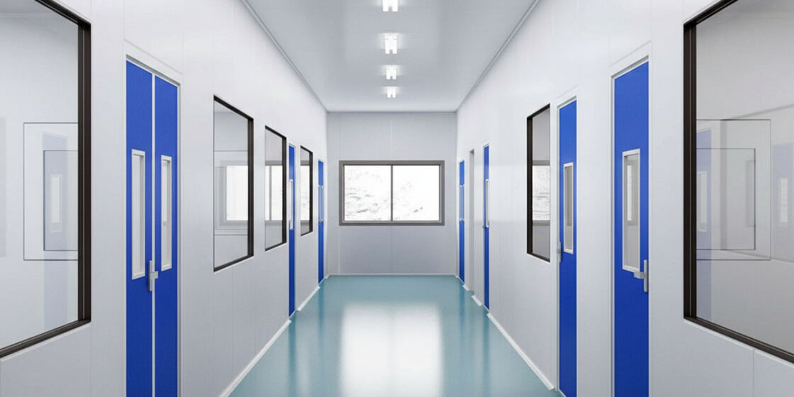
Facility planners often assume cleanrooms are static-free zones due to heavy air filtration. They are not. Low humidity and synthetic filtration media actually create an invisible threat where a discharge as low as 10 volts can destroy sensitive microchips or attract airborne particulates. Specifying the correct ESD clean room panels prevents these latent component failures, but only if you know how to read the engineering data.
Many engineers confuse generic anti-static materials with true static dissipative walls, which leads to buying non-compliant panels that fail ANSI/ESD S20.20 audits. After 15 years of engineering composite systems at Rax Panel, we mandate a surface resistivity between 10^6 and 10^9 ohms to ensure a controlled path to ground.
This overview decodes the specifications you need, comparing conductive versus dissipative classifications, breaking down charge decay thresholds, and evaluating core materials like aluminum honeycomb and mineral wool. You will walk away with the evaluation parameters needed to ensure your next facility passes strict regulatory audits without costly surprises.
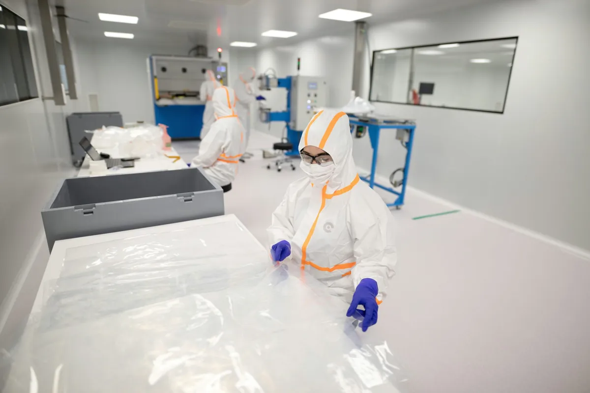
ESD Cleanroom Panel Specifications: Direct Technical Answer
ESD cleanroom panels are conductive composite wall systems engineered to maintain 10^6–10^9 ohm surface resistivity—bridging the gap between insulative surfaces that accumulate dangerous charges and fully conductive materials that risk current spikes capable of destroying sensitive microelectronics.
The controlled dissipation window between 10^6 and 10^9 ohms represents the engineering sweet spot for electrostatic protected areas (EPAs). Below 10^6 ohms, materials become conductive enough to generate current spikes that physically destroy semiconductor junctions and damage CMOS circuitry.
Above 10^9 ohms, triboelectric charges accumulate faster than they bleed off, reaching potentials that cause latent defects—invisible damage that passes quality inspection but fails catastrophically in field operation. ESD cleanroom panels solve this by embedding conductive carbon networks or metallic particle matrices directly into the panel facing during lamination, creating a permanent, stable dissipation path that does not degrade with repeated chemical wipe-downs.
This integral construction is the critical distinction between engineered ESD composite panels and topical anti-static treatments. Sprayed or wiped anti-static coatings typically wash off after 50–100 cleaning cycles with isopropyl alcohol or quaternary ammonium disinfectants. For facilities operating under ANSI/ESD S20.20 or IEC 61340-5-1 compliance programs, this degradation creates an invisible audit liability—surfaces that tested compliant at installation but silently drift outside specification months later. Engineered panels eliminate this risk by making the conductive network structural rather than superficial.
Facing Material Comparison: Matching Skins to Applications
{‘type’: ‘table’, ‘headers’: [‘Facing Material’, ‘Surface Resistivity Range’, ‘Chemical Resistance Profile’, ‘Typical ISO Class Application’], ‘rows’: [[‘Conductive GRP/FRP (Carbon-Loaded Gelcoat)’, ’10^6 – 10^9 Ω (Dissipative)’, ‘High resistance to IPA, QUATs, mild acids; stable after 1,000+ wipe-down cycles’, ‘ISO Class 5–7 (Semiconductor fab, Medical Device Assembly)’], [‘Stainless Steel (304/316 Grade)’, ‘< 10^6 Ω (Conductive; requires facility grounding integration)’, ‘Excellent against virtually all cleanroom chemicals including H₂O₂ vapor and chlorine dioxide’, ‘ISO Class 5–6 (Pharmaceutical Grade A/B, Biotech Sterile Suites)’], [‘Coated Aluminum / ACP with ESD Layer’, ’10^6 – 10^9 Ω (Dissipative)’, ‘Moderate; susceptible to pitting from alkaline cleaners above pH 10’, ‘ISO Class 7–8 (General Electronics Assembly, Packaging Zones)’], [‘Conductive HPL (Compact Laminate)’, ’10^6 – 10^9 Ω (Dissipative)’, ‘Good against standard hospital-grade disinfectants; limited resistance to concentrated acids’, ‘ISO Class 6–8 (Laboratory Partitions, Equipment Enclosures)’]]}
In our experience supplying ESD composite panels to manufacturers across 50+ countries, the most common specification error we see is treating chemical resistance as a secondary checkbox. A panel can pass every resistivity test on delivery yet fail within 6–12 months if its conductive network degrades under aggressive sterilization protocols—particularly hydrogen peroxide vapor (HPV) decontamination cycles used in pharmaceutical Grade A/B environments.
Our engineering team consistently recommends specifying panels where the conductive carbon network is co-cured into the gelcoat layer during lamination, not applied as a post-process surface treatment. This structural integration is the difference between a 10-year asset and a recurring replacement cost.
Three Critical Evaluation Parameters
When comparing ESD cleanroom panel suppliers, three technical parameters separate compliant long-term systems from costly procurement mistakes. Each parameter should be verified against third-party test documentation with specific standard references—not supplier marketing language.
📋 Actionable Steps
- Step 1: Electrostatic Performance Range Stability: Demand test data per ANSI/ESD STM11.11 or IEC 61340-2-3 showing surface resistivity measured not only at delivery, but after accelerated aging—typically 1,000 hours at 70°C and 95% relative humidity. Panels that drift outside the dissipative window after thermal cycling create undetectable field reliability risks that surface only as downstream warranty returns and latent defect claims.
- Step 2: Cleanroom Classification Compatibility: Verify that the panel’s molecular outgassing profile meets ISO 14644-1 contamination limits for the target cleanliness class. Panels acceptable for ISO Class 7 general assembly may exceed TVOC thresholds for ISO Class 5 semiconductor photolithography areas. Request specific AMC (Airborne Molecular Contamination) data—particularly for silicone and phthalate emissions from adhesive and core resin systems that can poison optics and wafer surfaces.
- Step 3: Structural Integrity and Fire Compliance: Require jurisdiction-appropriate fire certification—EN 13501-1 Euroclass for European projects, ASTM E84 for North American installations, or GB 8624 for domestic Chinese facilities. For modular wall systems carrying equipment loads or integrated lighting and utility raceways, demand documented deflection limits and point-load capacity verified through structural testing appropriate to the core material type.
Even the highest-specification ESD panel will fail an ANSI/ESD S20.20 compliance audit if the installation lacks continuous electrical grounding below 1.0 × 10^6 ohms end-to-end. We have audited facilities where fully compliant panels were rendered functionally useless by non-conductive silicone sealants applied at panel joints, or by isolating EPDM gaskets at base track interfaces. Always specify conductive gaskets, verify panel-to-panel continuity with a megohmmeter after installation, and document resistance readings at every grounding point before commissioning the EPA.
| Feature Category | Technical Specification | Performance Benefit |
|---|---|---|
| Panel Facings (Skins) | GRP/FRP (with Gelcoat), Stainless Steel, Aluminum (ACP) | Provides a non-porous, smooth surface that is easy to clean, corrosion-resistant, and chemically stable for strict hygiene standards. |
| Core Materials | Aluminum Honeycomb, PU (Polyurethane), PIR (Polyisocyanurate), Mineral Wool | Delivers high strength-to-weight ratios, superior thermal insulation, and structural integrity suitable for modular wall systems. |
| ESD Control Properties | Conductive and Static Dissipative Coatings / Finishes | Safely dissipates electrostatic charges to prevent latent damage to sensitive electronics and comply with ESD safety standards. |
| Fire Safety Rating | Mineral Wool / PIR Cores with Fire Retardant Facings | Offers high fire resistance to meet strict building codes and safety regulations. |
| Compliance & Standards | Industrial, Medical, and Construction Grade Standards | Ensures the controlled environment meets rigorous contamination control requirements for diverse global applications. |
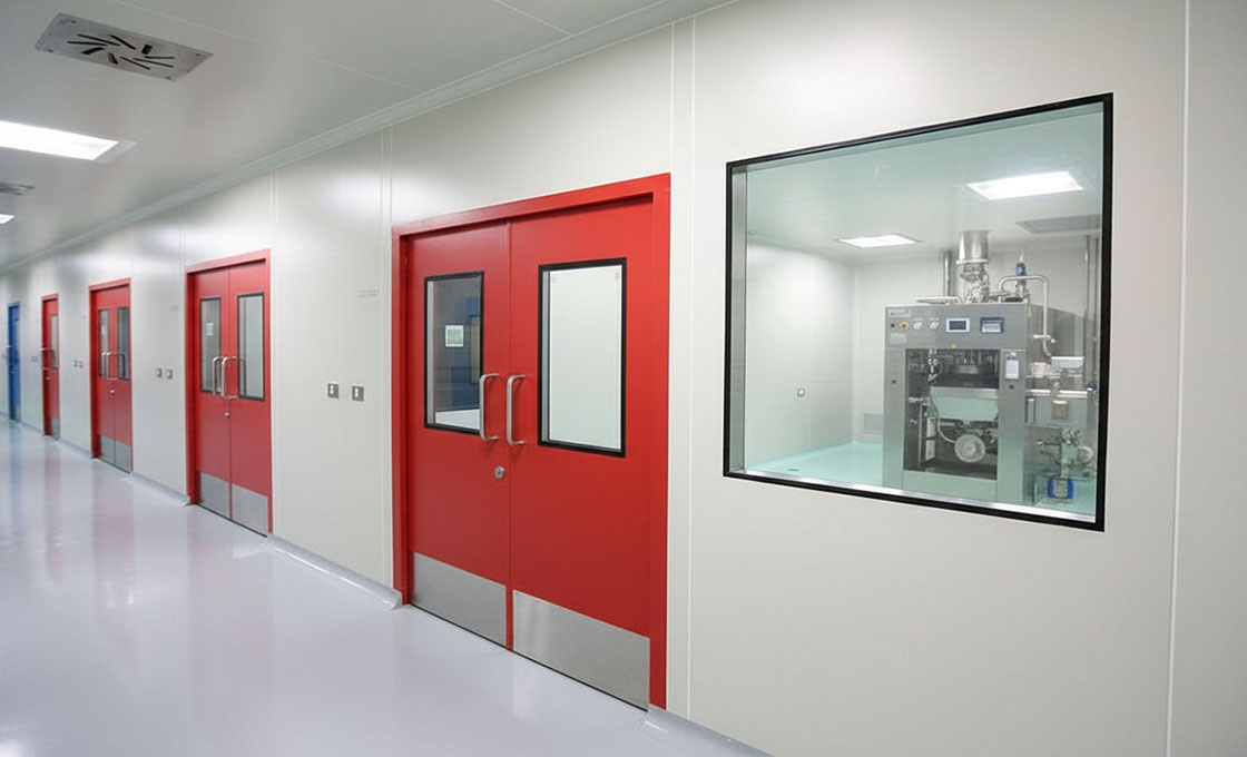
Anti-Static vs Static Dissipative vs Conductive Classification
How to Choose the correct electrostatic category—anti-static, static dissipative, or conductive—is a strict engineering necessity, not marketing semantics. Misclassifying these materials directly compromises ANSI/ESD S20.20 compliance and risks catastrophic latent defects in sensitive manufacturing environments.
Terminology Disambiguation: Anti-Static vs. Static Dissipative vs. Conductive
In the supply chain, suppliers frequently use ‘anti-static’ as a catch-all buzzword, deliberately or accidentally blurring the lines between three distinct electrostatic properties. This creates massive confusion for buyers evaluating technical specifications. To specify the correct composite panels, you must evaluate materials based on their surface resistivity (measured in Ohms) and their specific charge protection mechanism.
📋 Actionable Steps
- Step 1: Anti-Static (Typically 10^9 to 10^11 Ω): These materials are formulated to inhibit tribocharging—meaning they resist generating a static charge when rubbed against other materials. However, they do NOT provide a fast path to ground. They will not safely drain an existing electrical charge.
- Step 2: Static Dissipative (10^6 to 10^9 Ω): This is the optimal zone for ESD-safe environments. These panels allow electrical charges to flow to the ground in a controlled, slow manner. This prevents sudden, damaging sparks while effectively neutralizing the surface.
- Step 3: Conductive (10^2 to 10^6 Ω): These materials offer very low electrical resistance, allowing charges to flow rapidly. While excellent for grounding heavy equipment, conductive wall panels carry a higher risk of generating a damaging ESD event if a charged object approaches the surface too quickly.
At Rax Panel, our engineering team strictly differentiates these metrics. For semiconductor and medical device cleanrooms, we manufacture GRP/FRP panels engineered to maintain a true static dissipative range (10^6 to 10^9 Ω) by integrating specialized conductive carbon matrices into the skin resins, ensuring controlled charge decay without spark risks.
Using generic ‘anti-static’ panels in a facility requiring ESD control is a critical compliance failure. ANSI/ESD S20.20 standards mandate that all surfaces in the EPA (ESD Protected Area) must be actively grounded. Because anti-static materials lack the conductivity to move charges to ground, they will fail third-party surface resistivity audits and leave your facility ungrounded.
The Cleanroom Static Paradox
To achieve strict ISO classifications, cleanrooms utilize massive HVAC systems pushing high-velocity air through synthetic HEPA and ULPA filtration media. This continuous, fast-moving airflow strips moisture from the environment, often dropping relative humidity to 30% or lower. In this ultra-dry state, the natural microscopic layer of moisture on material surfaces disappears, significantly increasing triboelectric charging. Instead of mitigating static, a cleanroom effectively acts as an ideal incubator for high-voltage electrostatic accumulation.
Because the environment inherently generates and traps these charges, relying on passive ‘anti-static’ properties is entirely insufficient. The facility’s wall panels must serve as an active, reliable pathway to the facility’s grounding grid. Using properly specified static dissipative composite panels ensures that the massive static charges generated by dry laminar airflow and moving personnel are safely drained before they can attract airborne particulates or discharge into sensitive microprocessors.
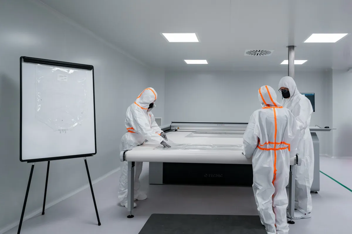
Surface Resistivity & Electrostatic Performance Parameters
Avoid cleanroom panels that rely on temporary anti-static sprays or migrant chemical additives to achieve ESD compliance. In ISO Class 5 environments, routine wiping with isopropyl alcohol (IPA) will strip these topical treatments in weeks, causing immediate resistance spikes that will fail a regulatory inspection and expose sensitive electronics to uncontrolled static accumulation.
Engineering Permanent Electrostatic Performance
In our advanced composite manufacturing facility, we eliminate the risk of electrical drift by integrating conductive carbon matrices directly into the panel’s structural skin during the layup process. Whether fabricating gel-coated GRP sheets or coated aluminum facings, our engineering team conducts rigorous experimental testing to lock the surface resistivity into that exact 10^6 to 10^9 ohm dissipative window. This guarantees uniform electrostatic performance across our entire 1,700 square meter daily production output, ensuring global distributors receive a consistent, compliant product.
📋 Actionable Steps
- Step 1: Require Precise Ohmic Data: Do not accept generic ‘ESD safe’ labeling. Insist on manufacturer data sheets explicitly stating a surface resistivity range of 10^6 to 10^9 ohms tested per ASTM D257.
- Step 2: Audit the Manufacturing Method: Confirm whether the dissipative property is a fragile topical spray or permanently integrated into the composite matrix (FRP/GRP or Aluminum).
- Step 3: Request Batch Testing Certificates: Ensure the manufacturer provides internal lab verification for electrostatic consistency for each production run, not just a single initial sample test.
When evaluating composite panels for semiconductor or medical device cleanrooms, prioritize materials that maintain their 10^6 to 10^9 ohm dissipative range even at relative humidities below 30%. Low-humidity stress testing is the true indicator of a permanently engineered, high-performance ESD panel.
Static Decay Rate & Charge Generation Thresholds
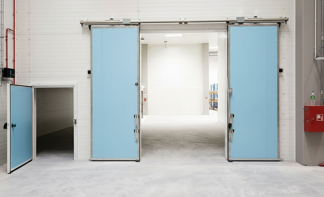
Static control is not just about surface resistance; it is about the speed of dissipation. A panel that cannot bleed off 1,000V to safe levels in under 0.01 seconds is a latent defect liability in high-speed manufacturing environments.
In electronics manufacturing and sensitive cleanrooms, the primary anxiety for facility engineers is Latent Component Failure. Unlike catastrophic failures that destroy a chip immediately, latent defects weaken components over time, causing product failures in the field and voiding warranties. To mitigate this, buyers must look beyond basic resistivity and evaluate the dynamic performance of Static Decay Rate and Charge Generation Thresholds.
Static Decay Rate Metrics
Quantifying the exact duration a charged surface requires to safely dissipate its electrical energy defines the Static Decay Rate. Specifically, it measures the duration in seconds for a 1,000V charge to reduce to 100V, representing 10% of the initial voltage when the panel is properly grounded. While ANSI/ESD S20.20 requires a decay time of less than 2.0 seconds, advanced semiconductor and precision electronics environments frequently mandate rapid decay under 0.10 seconds to handle high-speed manufacturing processes.
Do not assume that a panel labeled ‘conductive’ automatically complies with decay standards. If the panel’s core material or the interface between the skin and the core introduces resistance, the charge may be trapped in the surface layer, slowing the decay rate significantly. Always verify decay data, not just surface resistivity.
Charge Generation Thresholds
While decay rate addresses how fast a charge leaves, Charge Generation Thresholds focus on how much voltage is created in the first place. When materials rub against each other—such as cleanroom carts, personnel clothing, or airflow friction—triboelectric charging occurs. If a wall panel has a high charge generation threshold, it acts as a battery, constantly injecting new static into the environment even if the ground system is working perfectly to remove it.
Our R&D lab focuses heavily on the triboelectric properties of our facing materials. We utilize specialized conductive gel coats and modified FRP resin systems in our GRP/FRP sandwich panels. This formulation minimizes the initial voltage generation upon contact, ensuring our panels act as passive shields rather than active static generators, particularly in low-humidity cleanrooms where static generation is naturally amplified.
Facing Material Specifications & Conductive Skin Options
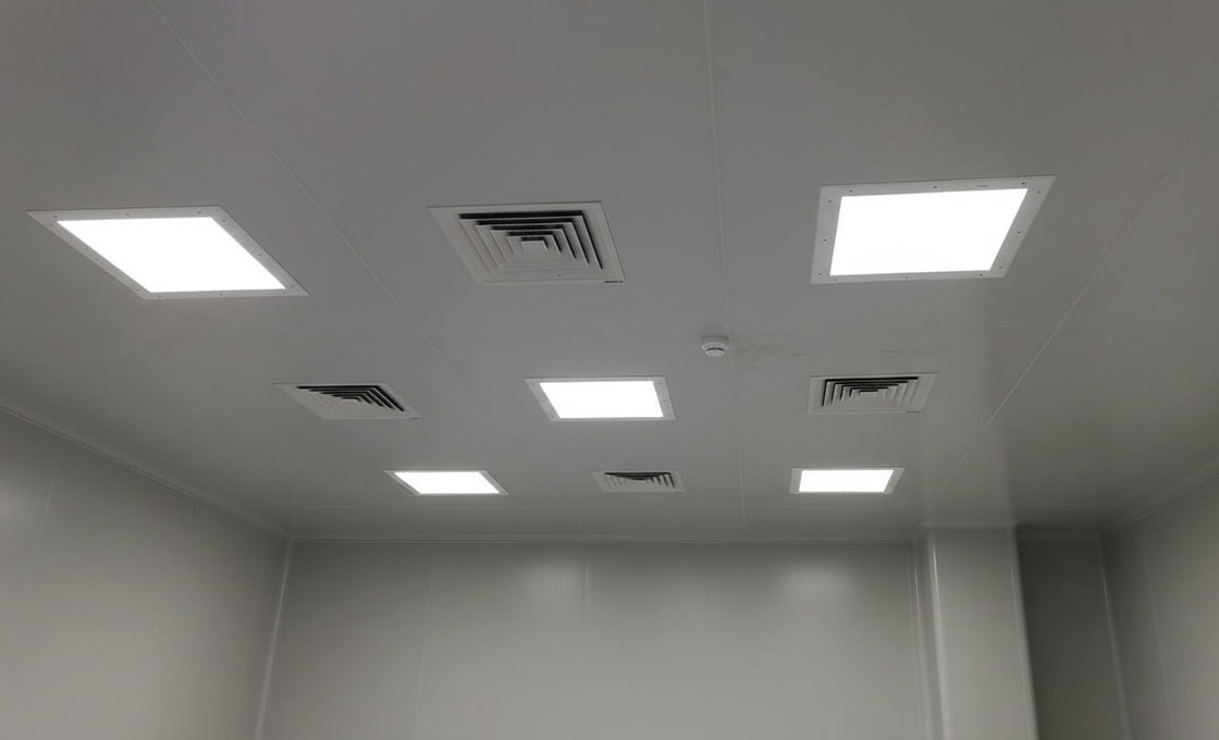
The facing material is not just a protective shell; it is the active electrical interface that determines whether your cleanroom meets ANSI/ESD S20.20 standards or risks latent component failure.
Facing Material Variants: HPL, Steel, and GRP
How to Choose the correct facing material is a critical decision point that separates a compliant facility from a liability hazard. The industry typically offers three primary facing options: High-Pressure Laminate (HPL), Galvanized or Stainless Steel, and Glass Reinforced Plastic (GRP/FRP).
While HPL is frequently chosen for its low initial cost, it is notoriously prone to chipping, delamination, and moisture ingress under mechanical stress, which immediately compromises the ESD seal. Steel offers durability but adds significant weight, complicating the load-bearing calculations for suspended ceilings and wall partitions.
Conductive GRP/FRP: The Composite Advantage
GRP/FRP facings have emerged as the superior engineering solution for modern ISO Class 5-8 environments. Unlike brittle laminates, our FRP skins utilize a continuous fiberglass mat that provides high tensile strength and impact resistance without the weight penalty of steel. Crucially, the smooth gelcoat finish on our FRP sheets is not merely aesthetic; it ensures a non-porous, waterproof surface that prevents microbial growth and withstands aggressive cleaning agents, a non-negotiable requirement for pharmaceutical and medical device manufacturing.
Conductive Skin Implementation: Carbon Veil vs. Coatings
Achieving consistent surface resistivity requires integrating a conductive medium directly into the skin structure. We distinguish heavily between simple conductive paint coatings and integrated carbon fiber veils. Surface-only coatings are susceptible to abrasion and cleaning agents, leading to ‘hot spots’ where resistivity spikes and static charges accumulate uncontrollably.
In our production process, we embed a continuous carbon fiber veil layer between the gelcoat and the fiberglass reinforcement. This construction ensures that even if the surface gelcoat is scratched during maintenance, the underlying conductive path remains intact, maintaining the required 10^6 to 10^9 ohm impedance for the panel’s service life.
When specifying stainless steel facings for wet process environments, never rely solely on mechanical fasteners for grounding. Thermal expansion can loosen screws over time, breaking the ESD circuit. Always insist on welded grounding tabs or verified conductive backing to ensure permanent electrical continuity.
Core Material Composition: Rockwool, Honeycomb & PU/PIR
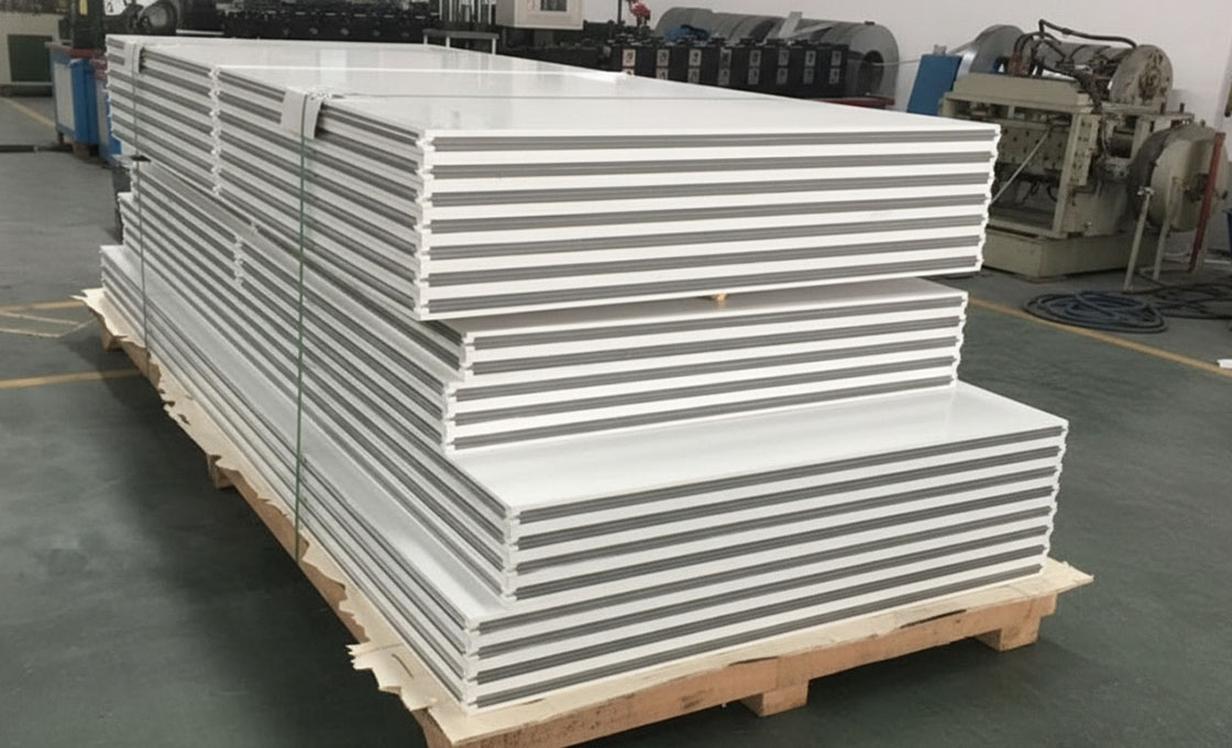
Core material selection in ESD cleanroom panels is not an engineering preference—it is a compliance mandate. The choice between rockwool, PIR foam, and aluminum honeycomb determines whether your facility passes a GMP audit or maintains thermal stability in controlled environments.
The core of an ESD cleanroom panel does more than fill space between facings—it defines fire classification, thermal conductivity, structural load, and even the panel’s grounding pathway. Most specification errors occur when buyers treat the core as a commodity rather than a regulatory decision driver. The tension between budget optimization and certification compliance is where projects either succeed or fail audit.
A generic foam panel may look identical to a certified rockwool panel on the installation drawings. The difference surfaces when an inspector demands fire documentation, or when a pharmaceutical cold room cannot hold temperature because the core’s lambda value was never verified. Replacing non-compliant panels after a failed audit costs 4–6x the original installation budget when you factor in downtime.
Rockwool (Mineral Wool) Core — The Regulatory Default
Rockwool is the mandatory specification for any inspected environment: pharmaceutical manufacturing suites, hospital operating theaters, food processing facilities, and any space where a regulatory authority will audit the building envelope. It satisfies fire compliance requirements unambiguously—no exceptions, no conditional approvals. Thermal conductivity (lambda) runs approximately 0.035–0.038 W/m·K, which is functional but not class-leading. The trade-off is mass: mineral wool cores are significantly heavier than foam alternatives, requiring engineered mounting tracks and verified structural supports.
In our daily production of over 1,700 square meters, a substantial volume serves pharmaceutical and medical clients across Europe and the Middle East. Our engineers verify mineral wool density, fiber orientation, and fire classification documentation on every production run before lamination begins. For audited facilities, the paper trail is as critical as the physical panel—if the core cannot be traced to a certified source with documented fire performance, the panel is non-compliant regardless of how well it performs in testing.
PU and PIR Foam Cores — Thermal Performance Leaders
PIR (polyisocyanurate) foam delivers the highest thermal insulation available in a commercial sandwich panel core. Lambda values of 0.022–0.024 W/m·K represent roughly 50% better thermal resistance than rockwool at equivalent thickness. PU (polyurethane) foam offers near-identical thermal performance with different fire behavior characteristics. These cores are the correct specification when thermal performance—not fire classification—drives the engineering: cold chain pharmaceutical storage, refrigerated truck bodies, temperature-controlled logistics facilities, and food processing cold rooms.
The weight advantage compounds the thermal benefit. PIR and PU cores are dramatically lighter than rockwool, reducing shipping costs, simplifying installation logistics, and lowering structural load requirements on support frameworks. However, they cannot achieve the A1-equivalent fire classification that rockwool delivers. Specifying PIR where code demands rockwool is a non-negotiable failure point.
Aluminum Honeycomb Core — Structural Optimization for Specific Geometries
Aluminum honeycomb offers the highest strength-to-weight ratio of any cleanroom panel core, but it is functionally a poor thermal insulator. Its R-value per millimeter falls far below any foam option. This makes honeycomb inappropriate for wall partitions where thermal separation is required but well-suited for ceiling panel systems where the thermal envelope is handled by the plenum space above, not by the ceiling panel itself.
For wall applications, rockwool is the preferred core unless extreme weight constraints or specific structural load requirements mandate honeycomb. Honeycomb cores also require careful ESD integration—the aluminum structure is inherently conductive, which can either support or disrupt the panel’s grounding architecture depending on how the facing materials and edge details are engineered.
Specifying PIR foam where rockwool is mandated by building code will fail GMP, FDA, or local fire authority audits and require complete panel replacement. Conversely, over-specifying rockwool in a cold storage application wastes budget on unnecessary fire compliance while delivering inferior thermal performance. Always confirm the regulatory requirement matrix before finalizing core selection—never assume, and never let a supplier default to a core without documented justification.
For ESD-controlled environments specifically, the core material must integrate with the panel’s overall grounding architecture. A non-conductive foam core can create an isolated capacitive zone between conductive facings, trapping charge rather than dissipating it. Our engineering team tests core conductivity integration during prototyping—verifying that the panel’s ESD performance is consistent through the full cross-section, not just at the surface layer. This is why we offer customized core formulations: the right core for an ESD-rated pharmaceutical wall differs from the right core for an ESD-rated ceiling, even within the same ISO class facility.
Fire Rating Classifications & Structural Load Capacity
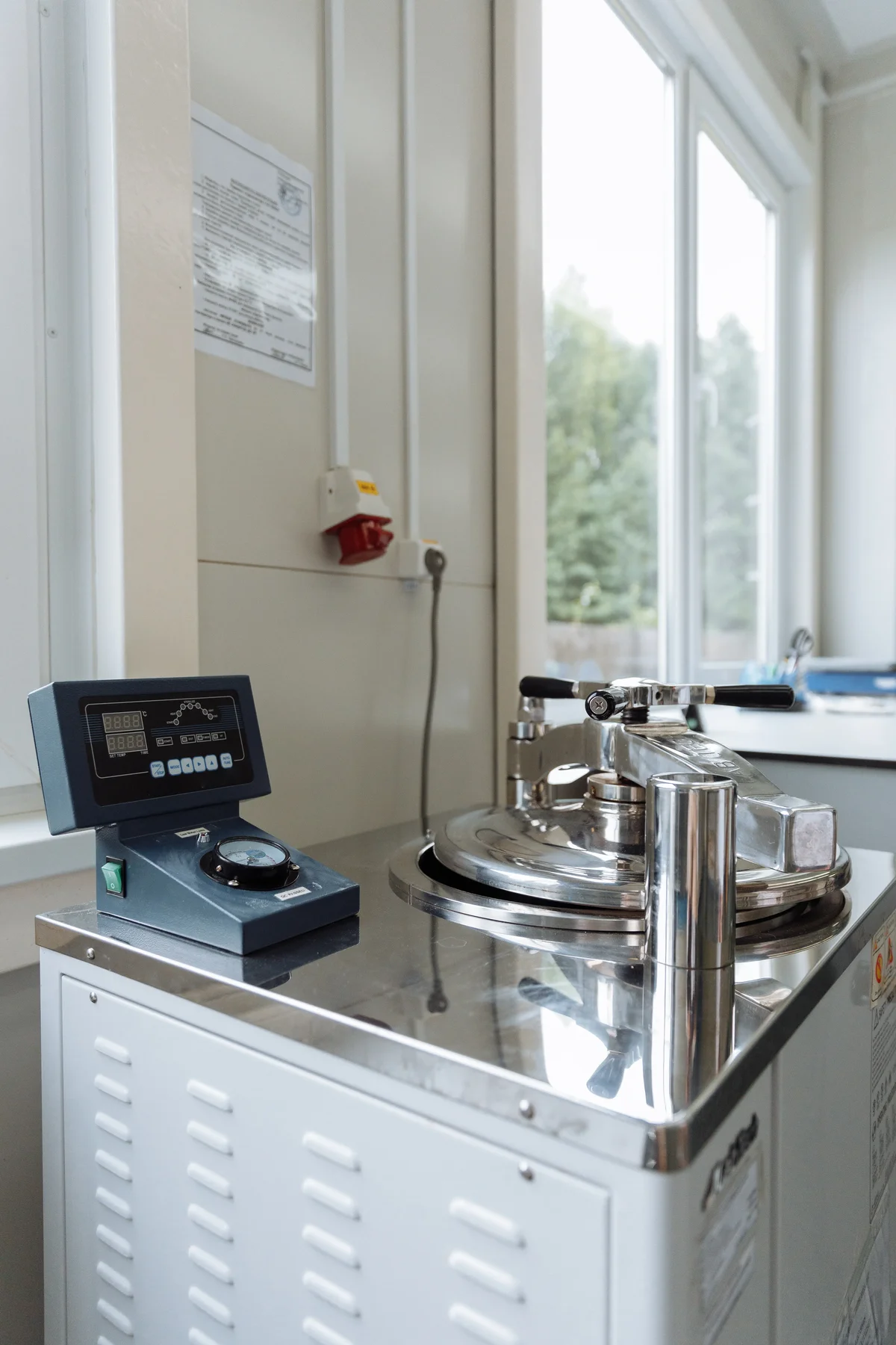
Fire resistance and structural load capacity are the two parameters that will make or break a cleanroom certification audit. A panel that dissipates static perfectly but fails a 2-hour fire endurance test is a liability, not a solution.
In regulated cleanroom environments—pharmaceutical GMP facilities, semiconductor fabs, medical device manufacturing—fire performance is not a marketing feature. It is a legal prerequisite embedded in building codes and facility validation protocols. Most jurisdictions across Europe, North America, and the Middle East enforce mandatory fire performance and fire resistance ratings on wall and ceiling panel systems before a facility receives operational approval.
Fire Performance Classification vs. Fire Resistance Rating: Two Different Metrics
Buyers frequently conflate these two parameters, and suppliers rarely clarify the distinction. Fire performance classification (such as EN 13501-1 Euroclass A1 through F, or ASTM E84 Flame Spread Index) measures the inherent combustibility and smoke contribution of the material itself. Fire resistance rating (expressed as REI 60, REI 120, up to REI 240) measures how long a complete panel assembly maintains structural integrity, insulation, and flame containment under fully developed fire conditions. You need both documented for audit compliance.
Fire performance classification is driven primarily by core chemistry. Mineral Wool and Rockwool cores achieve non-combustible A1/A2 ratings, making them the default selection for facilities with the most stringent fire code requirements.
PIR (Polyisocyanurate) foam cores deliver a self-extinguishing compromise—rated B or C under EN 13501—while providing substantially better thermal insulation performance per millimeter of thickness than mineral-based cores. PU foam cores sit lower on the classification scale but deliver cost-efficient lightweight structures for applications where lower fire classifications are acceptable under local code.
Fire resistance rating, by contrast, is a function of the entire assembly: total panel thickness, core density, facing material gauge, adhesive system, and joint profile. A 50mm Rockwool core panel may achieve REI 60 in a standardized test.
The same core material at 100mm thickness, paired with reinforced edge detailing and a properly engineered cam-lock joint system, can extend resistance to REI 180 or beyond. Industry-leading cleanroom panel systems now achieve up to 4 hours of fire resistance through strategic combinations of core thickness, core composition, and joint design.
Request the full assembly test report, not just a core material data sheet. A Rockwool core rated at REI 120 in one supplier’s lab may perform differently when the facing gauge, adhesive formulation, or panel joint profile changes. We provide complete assembly-level fire test documentation tied to the exact production configuration shipped to your facility—no ambiguous cross-referencing between component data and finished panel performance.
Structural Load Capacity: Engineering Walls and Ceilings Differently
Cleanroom wall panels serve a dual structural function: environmental enclosure and partition support. Standard wall partitions typically span 3 to 5 meters in height and must resist self-weight deflection without visible deformation or joint separation. For conventional enclosure applications at this height range, a 0.5mm galvanized steel facing on both sides of a structural core generally meets lateral stability requirements under normal cleanroom operating conditions.
Ceiling panels demand substantially more engineering rigor. Unlike walls, cleanroom ceilings frequently carry concentrated mechanical loads: HEPA housing units weighing 40-80kg each, lighting troffers, cable trays, utility drops, and in some facilities, walkable maintenance access platforms. Load-bearing calculations must account for point loads at penetration locations, uniform distributed loads across the grid span, and the deflection limits dictated by cleanroom classification requirements.
Load Enhancement Strategies and Cost Trade-Offs
When standard panel configurations fall short of project-specific load requirements, three engineering interventions are available. Each carries distinct cost and weight implications that directly impact project budgets.
📋 Actionable Steps
- Step 1: Edge keel reinforcement: Thickening the perimeter keel material on each panel increases load transfer efficiency to the support grid. This is the lowest-cost intervention, typically adding 5-8% to panel cost while improving point-load capacity at joints and mounting locations.
- Step 2: Internal reinforcement profiles: Embedding structural ribs or hat sections into the core matrix during lamination creates load paths independent of the core material itself. This adds 10-15% to panel cost but significantly improves both point-load and distributed-load performance without increasing overall panel thickness.
- Step 3: Core density upgrade: Switching from standard-density core material to a higher-density variant (e.g., upgrading Rockwool from 60kg/m³ to 100kg/m³, or PU foam from 35kg/m³ to 50kg/m³) increases compressive strength across the entire panel surface. Cost impact ranges from 12-20% depending on the density step selected.
Our engineering team conducts structural load calculations based on your specific architectural drawings before production begins. We have consistently found that over-specifying panel thickness uniformly across an entire cleanroom is the most common cost drain in projects. Targeted reinforcement at high-load zones—ceiling penetrations, equipment mounting walls, HVAC equipment platforms—typically delivers the required load performance at 20-30% lower total material cost than uniformly thickening every panel in the envelope.
Fire safety auditors and insurance assessors require documentation that links the entire panel assembly to the claimed fire resistance rating. A supplier providing only a core material fire classification certificate—without matching assembly-level test reports for the specific facing gauge, adhesive system, joint profile, and panel thickness shipped—will not pass a rigorous third-party validation. Before committing to a supplier, request assembly-level fire resistance test reports, structural load calculation documentation signed by a qualified engineer, and traceability between the certified test specimen and the production configuration delivered to your facility.
Key Takeaways
Look, the bottom line is clear: never compromise on that surface resistivity range of 10^6 to 10^9 ohms just to save a few bucks. If you choose the wrong facing material or overlook the ANSI/ESD S20.20 standards, you risk latent component failures and failed audits. Ensure your core selection—whether honeycomb or mineral wool—actually aligns with your specific ISO classification requirements, or you’ll pay for it later.
When you issue that PO, demand verified test data for decay rates and fire compliance. Any supplier who can’t explain the cleanroom static paradox or back up their claims with certifications isn’t worth your time. Stick with manufacturers who offer full technical traceability and support. In this market, buying cheap, non-compliant panels is a liability that will destroy your reputation faster than any budget savings can fix.
Frequently Asked Questions
This factor has a direct bearing on project performance and long-term cost. Addressing it with specific data rather than general assumptions leads to better outcomes.
What core materials are used in ESD panels?
High-quality ESD cleanroom panels typically utilize lightweight yet rigid core materials such as aluminum honeycomb, mineral wool, or various rigid foams. Aluminum honeycomb offers exceptional strength-to-weight ratios, while mineral wool provides superior fire retardancy and acoustic insulation. The specific choice of core depends heavily on the facility’s structural, fire-rating, and thermal insulation requirements. These advanced composite structures ensure the panels remain dimensionally stable even under stringent cleanroom conditions.
What surface resistance is required for ESD panels?
For proper electrostatic discharge control, ESD cleanroom panels must typically feature a surface resistance between 10^6 and 10^9 ohms. This specific resistance range, known as the dissipative range, allows electrical charges to flow slowly and safely to the ground. Materials with lower resistance might cause dangerous rapid discharges, while higher resistance traps the static charge on the surface. Meeting this resistance specification is crucial for compliance with strict ANSI/ESD S20.20 industry standards.
What finishes are available for ESD panels?
ESD cleanroom panels are typically available with HPL (High-Pressure Laminate) or specialized anti-static coatings that integrate conductive carbon networks. These finishes not only provide the necessary static dissipative properties but also offer excellent resistance to chemical sterilization agents. At , we ensure these surface finishes are smooth, non-shedding, and highly durable to maintain strict cleanroom compliance. Selecting the appropriate finish depends on your specific ISO class rating and chemical exposure risks.
What is the standard cleanroom panel thickness?
The standard thickness for cleanroom wall panels typically ranges from 50mm to 100mm, depending heavily on the specific application and thermal requirements. Thicker panels are generally utilized when higher structural integrity or enhanced thermal insulation is necessary for strict environmental control. offers customizable thicknesses to perfectly match your modular framework and structural load demands. Selecting the correct thickness ensures optimal cleanroom performance while maximizing usable interior floor space.
Do ESD cleanroom panels require special grounding?
Yes, to function correctly, ESD cleanroom panels must be properly integrated into the facility’s overall electrical grounding system. While the panel surfaces are engineered to dissipate static charges, that accumulated electricity requires a safe, continuous path to the earth. This is typically achieved by connecting the conductive panel layers directly to the grounded structural framework or specialized copper grounding strips. Proper grounding ensures that no static potential can build up on the walls to threaten sensitive electronics.