
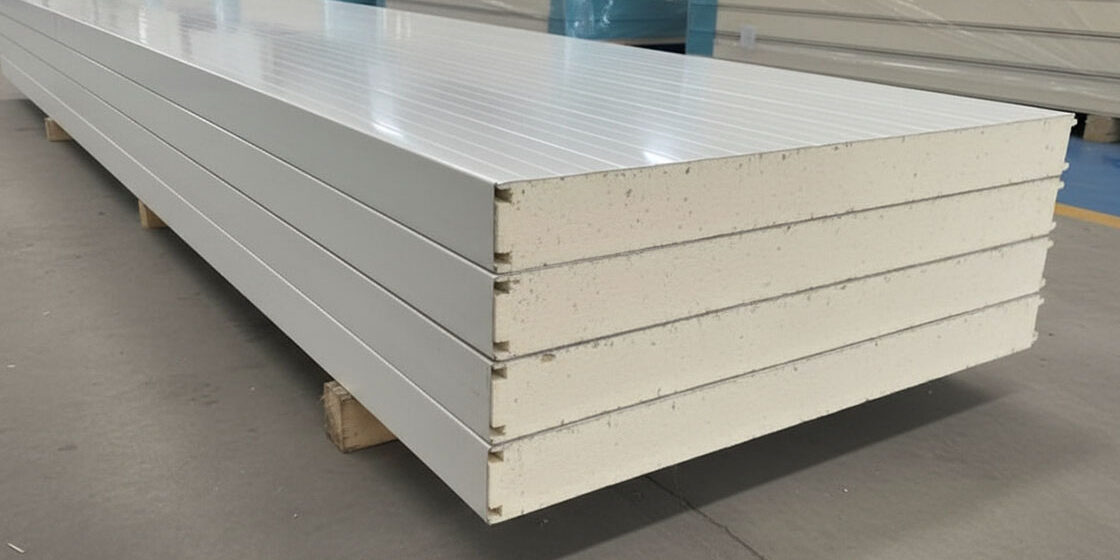
Most cold room failures aren’t caused by the refrigeration cycle itself. They stem from miscalculating the cooling load calculation because buyers ignore transmission loads through wall joints and solar heat gain on the roof. I spent 15 years watching operators undersize compressors, only to see their inventory spoil during peak summer months. The physics of the cold room refrigeration cycle is straightforward, but the engineering behind keeping that cold air inside requires precision.
Rax Panel manufactures over 1,700 square meters of composite panels daily, yet even our best insulation cannot compensate for poor thermal bridging at panel connections. Interstitial condensation inside those walls degrades performance over time, turning airtight seals into moisture traps. Understanding how heat transfers through these specific joints is the difference between a system that runs efficiently and one that burns electricity while failing to maintain temperature.
This guide explains the fundamental thermodynamics of the refrigeration cycle and details the critical role of panel insulation in preventing condensation. We will also break down exactly how to size your system by accounting for sunlight exposure and air infiltration. You will walk away with the ability to calculate your true heat load factors and select the right defrosting methods for your specific operational needs.
Core Refrigeration Principles Explained
A cold room’s efficiency hinges on the closed-loop refrigeration cycle and eliminating thermal bridges at panel joints.
Fundamental Thermodynamics of Heat Transfer
Heat transfer is the primary enemy of any cold storage system. In a cold room, thermal energy constantly moves from the warmer exterior environment toward the cooler interior. This happens through three main mechanisms: conduction (through solid walls), convection (via air movement), and radiation (from sunlight or warm surfaces).
For B2B buyers, understanding this is critical because it dictates your energy bills. If your insulation fails or has gaps, your refrigeration unit must work harder to remove that excess heat. We see this frequently in retrofit projects where older structures suffer from “thermal bridging”—areas where heat bypasses the insulation entirely.
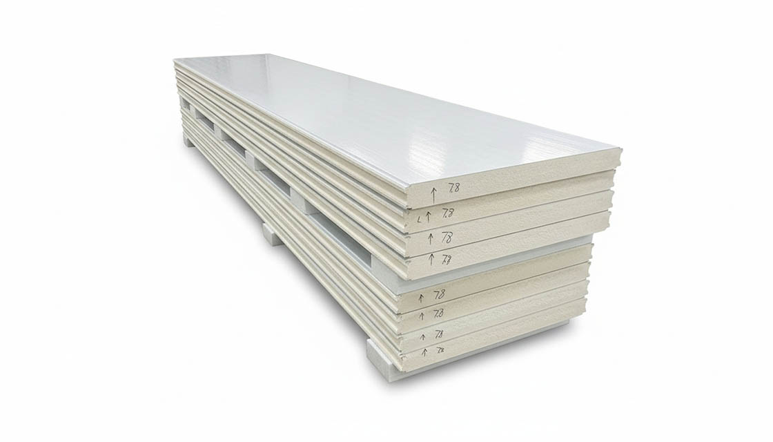
This is why the quality of your panel joints matters as much as the panel itself. A poorly sealed joint allows warm, moist air to penetrate the insulation core, drastically reducing the effective R-value. Our engineering team prioritizes tight-tolerance locking mechanisms to prevent these leaks, ensuring the thermal barrier remains intact.
Overview of the Closed-Loop Cooling Cycle
Refrigeration is essentially heat removal. The closed-loop cycle moves a refrigerant fluid through four key stages, absorbing heat inside the room and dumping it outside. Think of it like a sponge that soaks up heat in the cold room and wrings it out in the condenser unit.
The cycle is continuous and relies on pressure changes to alter the boiling point of the refrigerant. When pressure drops, the refrigerant boils and absorbs massive amounts of heat. When pressure rises, it condenses back into a liquid and releases that heat. Mastering this balance is what separates efficient cold rooms from energy hogs.
Key Components: Compressor, Condenser, Evaporator, Expansion Valve
- The Compressor: Often called the heart of the system, it pressurizes the refrigerant gas, raising its temperature significantly before sending it to the condenser.
- The Condenser: Located outside the cold room, this coil releases the absorbed heat into the ambient air. As it cools, the high-pressure gas turns into a high-pressure liquid.
- The Expansion Valve: This metering device creates a sudden pressure drop. It allows the liquid refrigerant to expand rapidly, cooling it down to near-freezing temperatures instantly.
- The Evaporator: Situated inside the cold room, this cold coil absorbs heat from the air. The refrigerant boils into a gas again, completing the loop and lowering the room temperature.

Cold Room Panel Insulation Role
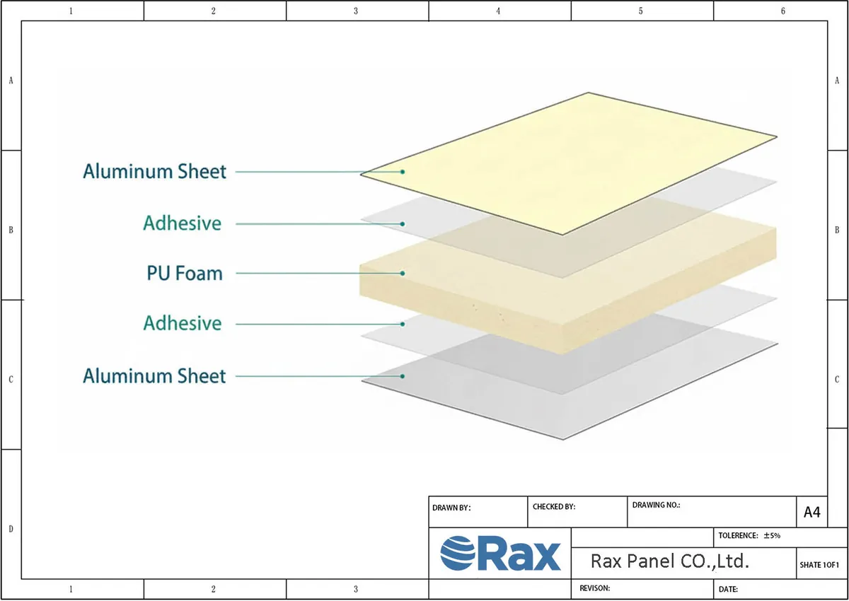
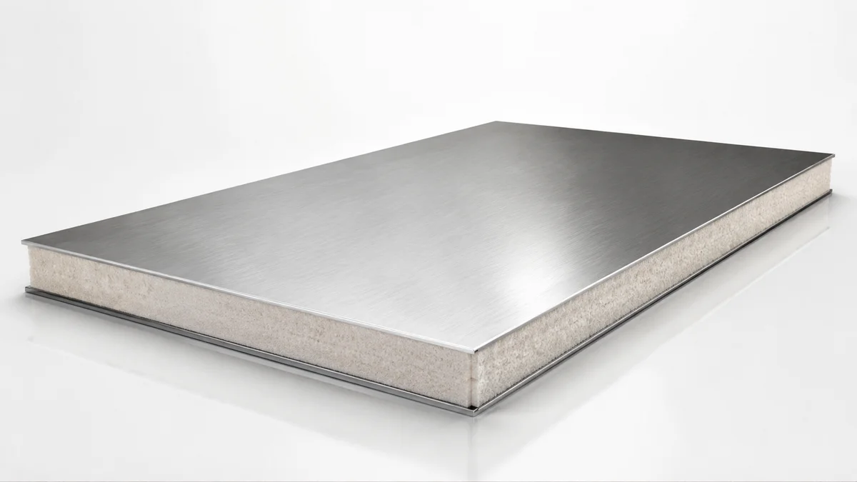
Cold room panel insulation serves as the primary thermal barrier, preventing external heat ingress while protecting structural integrity. By providing high thermal resistance and effective moisture control, the panels minimize energy consumption and safeguard the facility against hidden structural damage.
Thermal Efficiency of Cold Storage Panels
High-performance cold storage panels are engineered to maximize thermal resistance, minimizing the energy required to maintain internal setpoints. By reducing heat penetration to negligible levels, these panels allow refrigeration systems to sustain strict temperature ranges without continuous cycling, directly lowering operational costs. A well-engineered insulation core stabilizes the internal environment for temperature-sensitive goods, ensuring consistent conditions that protect product integrity over the long term.
Achieving this efficiency requires absolute consistency in the manufacturing process. In our facility, we see how even slight variations in foam density or core application can create thermal bridges—localized areas where heat bypasses the insulation. Our engineers strictly monitor the lamination and foaming processes to guarantee a homogenous core. This uniformity is what allows distributors to promise their clients predictable, low-energy cooling cycles regardless of the external climate.
Preventing Interstitial Condensation and Moisture Intrusion
Moisture invasion is the hidden enemy of thermal efficiency. When warm, humid air manages to seep into a refrigerated space, it immediately hits the cold surfaces inside the panel. This triggers interstitial condensation, where water droplets form inside the panel walls. Over time, this trapped moisture freezes, expands, and permanently degrades the insulation core, skyrocketing your energy bills while creating a breeding ground for mold.
Stopping this destructive cycle requires a perfect seal. Our team approaches this by engineering continuous, integrated vapor barriers directly into the composite panel structure. By utilizing high-quality GRP and CFRT facings bonded seamlessly to closed-cell cores, we physically block water vapor from penetrating the envelope. The joint design is equally critical; precision-milled cam locks and tight sealing grooves ensure that when panels are assembled, the vapor barrier remains unbroken across the entire cold room wall.
Impact of Panel Thickness on Transmission Loads
Transmission load calculations rely on Fourier’s Law, where thermal conductivity is inversely proportional to panel thickness. This load—the exact amount of thermal energy conducting through the cold room walls, roof, and floor—is primarily controlled by the insulated panel’s physical thickness.
Increasing panel depth raises the thermal resistance (R-value), which linearly reduces the rate of heat transfer (Q) by forcing heat to travel a longer, more resistant path to reach the interior. For B2B operators, lowering this load means you can specify smaller, more affordable refrigeration units and slash daily electricity consumption.
Specifying the correct thickness is a delicate balance between upfront material investment and long-term operating costs. We routinely see operators attempt to cut initial costs by specifying thinner panels for deep-freeze applications. This is a fatal engineering flaw.
Our design team assists buyers in calculating the precise transmission loads based on their specific ambient conditions and target interior temperatures. By matching the panel thickness accurately to the cooling load calculation, we ensure the refrigeration cycle operates efficiently without premature compressor failure.
| Parameter | Specification | Role | Material Options |
|---|---|---|---|
| Thermal Conductivity (k-value) | PU/PIR: ≤0.022 W/(m·K); XPS: ≤0.030 W/(m·K); PET: ≤0.034 W/(m·K) | Minimizes heat transfer through panel walls to maintain stable internal temperatures. | Polyurethane (PU), Polyisocyanurate (PIR), Extruded Polystyrene (XPS), Polyethylene Terephthalate (PET) |
| Fire Resistance Rating | PIR: Class B-s1,d0; Rockwool: Class A1 (Non-combustible); PU: Class B/C depending on additives | Prevents fire spread and ensures compliance with safety standards in enclosed cold storage environments. | Polyisocyanurate (PIR), Rockwool, Polyurethane (PU) |
| Structural Integrity & Load Bearing | Compressive Strength: ≥150 kPa; Facing Materials: GRP, Aluminum, Stainless Steel | Supports heavy cargo loads and resists deformation under temperature fluctuations and mechanical stress. | GRP/FRP, Aluminum, Stainless Steel, CFRT |
| Moisture & Vapor Barrier | Water Absorption: <1%; Closed-cell structure with integrated vapor barrier layers | Prevents interstitial condensation and ice formation within the panel core, preserving insulation efficiency. | XPS, PU, PIR, PET, PVC |
| Weight Efficiency | Core Density: 30-60 kg/m³; Lightweight facings available for optimized payload | Reduces overall cold room or refrigerated truck weight, improving energy efficiency and payload capacity. | PET Foam, XPS, PVC Foam, Honeycomb Cores |
Compressor Pressurizes Refrigerant
The compressor initiates the refrigeration cycle by mechanically elevating the pressure and temperature of the gaseous refrigerant.
Raising Pressure and Temperature of Gas
Mechanical compression drastically reduces gas volume, causing a simultaneous spike in pressure and temperature. This adiabatic heating process transforms the low-pressure vapor from the evaporator into a high-energy state, establishing the essential temperature gradient required for effective heat rejection. By elevating the refrigerant’s temperature well above ambient levels, the system ensures that thermal energy can naturally flow out of the cold room and dissipate through the condenser coils.
This transformation is critical because it creates the necessary temperature gradient between the refrigerant and the outside environment. By raising the refrigerant’s temperature well above ambient levels, the system ensures that heat can naturally flow out of the cold room and dissipate through the condenser coils. Without this pressure spike, the refrigerant would never reach a temperature high enough to release its absorbed heat effectively.
From an engineering standpoint, the efficiency of this stage relies heavily on the compressor’s ability to handle the specific pressure ratio required by the system. In our laboratory testing of integrated cold room systems, we consistently observe that maintaining optimal discharge pressures reduces mechanical strain on the motor. Our engineers design custom panel assemblies to minimize the thermal load, allowing the compressor to operate closer to its peak efficiency curve rather than fighting against excessive heat infiltration.
Driving the Refrigerant Flow Through the System
By maintaining a consistent pressure differential, the compressor drives the continuous circulation of refrigerant through the closed loop. Beyond merely increasing pressure, the compressor serves as the driving pump for the entire circuit. It draws low-pressure vapor from the evaporator and compresses it into a hot, high-pressure gas that is pushed toward the condenser.
Once the gas releases its heat and liquefies, the liquid travels through the expansion device and returns to the evaporator, where it absorbs interior heat and vaporizes once again—allowing the compressor to continuously move only vapor and sustain a steady, unidirectional flow throughout the system.
This constant circulation is what prevents the system from stalling. If the compressor fails to maintain this flow, the refrigerant will stagnate, pressure differences will equalize, and the cooling process will cease immediately. For large-scale commercial installations, we find that reliable flow dynamics are just as important as the compression ratio itself, ensuring that the evaporator always receives the metered amount of liquid needed to absorb interior heat efficiently.

Condenser Releases Absorbed Heat
The condenser rejects absorbed heat to the outside air, causing the refrigerant to shift from a high-pressure gas back into a liquid state.
Dissipating Heat to the External Environment
After the evaporator absorbs heat from inside the cold room, the refrigerant carries that thermal energy to the condenser unit, which sits outside the insulated space. Here, the goal is purely to reject that heat into the ambient atmosphere. In a typical air-cooled condenser, fans blow outside air across the condenser coils to facilitate this transfer. The hotter the surrounding environment, the harder the system must work to dump that heat.
This process is heavily influenced by the quality of the cold room’s insulation. If the panels allow external heat to leak into the storage space, the refrigerant picks up that extra thermal load before it even reaches the evaporator. Consequently, the condenser receives refrigerant that is already carrying more heat than necessary.
We have seen in our engineering assessments that high-performance composite panels, such as those with PU or PIR cores, significantly reduce this transmission load. By keeping the interior stable, the condenser only has to handle the heat generated by the stored product and the compressor itself, rather than fighting a constant battle against environmental infiltration.
Phase Change from Gas to Liquid State
As the refrigerant releases its heat to the outside air, it undergoes a critical physical transformation known as condensation. The refrigerant enters the condenser as a superheated gas. As it sheds thermal energy, it cools down until it reaches its saturation point. At this stage, the gas begins to turn into a liquid. This phase change is vital because it prepares the fluid for the next step in the cycle.
Condensation occurs at constant pressure, resulting in a subcooled liquid state that ensures complete phase change before expansion. The refrigerant leaves the condenser as a subcooled liquid, meaning it is slightly cooler than its boiling point at that specific pressure. This ensures that no gas bubbles remain in the line heading toward the expansion valve.
If the phase change is incomplete, liquid slugging can occur downstream, potentially damaging the compressor. Our team monitors these thermal dynamics closely during system design to ensure the condenser capacity is perfectly matched to the cold room’s specific heat rejection requirements.

Expansion Valve Depressurizes Fluid
The expansion valve drops refrigerant pressure to enable evaporation, then precisely meters flow to match the cooling load of the cold room.
Reducing Pressure to Lower Boiling Point
The expansion valve serves as the critical bridge between the high-pressure condenser and the low-pressure evaporator. Its primary mechanical function is to create a restriction that causes a significant drop in pressure for the liquid refrigerant passing through it.
Reducing pressure lowers the refrigerant’s boiling point, preparing the fluid for efficient heat absorption in the evaporator. By dropping the pressure below the saturation point corresponding to the ambient temperature, the liquid refrigerant begins to boil, transforming into a low-pressure two-phase mixture. This state change ensures the fluid is ready to absorb heat efficiently once it enters the evaporator coils.
The expansion valve does not actively cool the space but modulates refrigerant properties to enable low-temperature evaporation. Unlike the evaporator, which performs the actual heat absorption, the valve prepares the fluid for the necessary phase change by manipulating its physical state. Without this precise pressure drop, the refrigerant would remain liquid and fail to boil, rendering the subsequent cooling process ineffective.
Metering Refrigerant Flow into the Evaporator
Beyond pressure reduction, the expansion valve functions as a precision flow controller. It regulates the volume of liquid refrigerant injected into the evaporator based on the real-time cooling demand. In cold storage applications, this dynamic adjustment is vital for maintaining stable temperatures despite fluctuating door openings or product loads.
- Preventing Liquid Floodback: The valve ensures that only the exact amount of refrigerant required for evaporation enters the coil. If too much liquid flows in, it will not fully vaporize, potentially returning to the compressor as liquid and causing catastrophic mechanical failure.
- Optimizing Heat Transfer Surface: By matching the flow rate to the thermal load, the valve keeps the evaporator tubes partially filled with boiling liquid. This maximizes the surface area available for heat exchange, ensuring the cold room cools efficiently without wasting compressor energy.
- Maintaining Superheat: Advanced valves monitor the temperature of the refrigerant as it leaves the evaporator. They adjust the opening to maintain a specific degree of superheat, guaranteeing that only vapor returns to the compressor while the maximum possible amount of heat is extracted from the cold room air.
In our experience designing cold room refrigeration systems, the synergy between the expansion valve’s metering accuracy and the panel insulation quality determines overall energy efficiency. When the valve precisely controls the phase change, the cold room panels can effectively resist external heat intrusion without forcing the compressor to work harder than necessary.
Evaporator Absorbs Interior Heat
The evaporator absorbs interior heat to cool the space, then returns the low-pressure gas to the compressor to restart the cycle.
Cooling the Cold Room Air via Phase Change
The evaporator functions as the cooling engine of the cold room. It absorbs heat from the interior air, lowering the temperature to the setpoint. This process relies on the rapid evaporation of the refrigerant inside the coil fins.
As the refrigerant boils, it pulls thermal energy from the surrounding air. This is the core mechanism for maintaining stable storage conditions. In our experience designing refrigerated transport bodies, efficient heat absorption directly prevents product spoilage during transit.
Returning Low-Pressure Gas to the Compressor
After absorbing heat, the refrigerant transforms into a low-pressure gas. This gaseous state is critical because it allows the compressor to safely suck the fluid back in without liquid damage.
The compressor then pressurizes this gas, raising its temperature before sending it to the condenser. This return loop completes the refrigeration cycle, ensuring continuous and reliable cooling performance for your cold storage infrastructure.
Defrost System Manages Frost
Frost accumulation on evaporator coils degrades thermal transfer efficiency, forcing the compressor to consume excess energy. This thermal resistance traps cold within the system, creating a vicious cycle where increased mechanical load accelerates wear and drives up operational costs. Implementing robust defrost strategies is essential to break this cycle, preventing energy waste and averting premature equipment failure.
Why Ice Accumulation is a Silent Killer
When moisture in the air hits the freezing cold evaporator coils, it instantly turns into ice. This layer of frost is not just water; it is a thick blanket of insulation. Even a thin layer of ice significantly reduces the coil’s ability to absorb heat from the room. To maintain the target temperature, the compressor must run longer and harder. This leads to massive spikes in electricity bills and shortens the lifespan of the machinery.
Beyond energy costs, ice buildup restricts airflow. If the air cannot move freely through the coils, the system loses its cooling capacity. In extreme cases, the ice can grow so large that it physically blocks the fan, causing the evaporator to freeze completely solid. Our engineers have seen numerous cases where operators ignored early signs of frost buildup, only to face total system failure during peak season.
Choosing the Right Defrost Strategy
There is no single “best” method for every cold room. The choice depends on your budget, the type of product stored, and the available infrastructure. You need to match the defrost mechanism to the specific operational demands of your facility.
- Economic Impact: Hot gas defrost is the most energy-efficient option because it recycles waste heat. However, it requires complex piping and a larger upfront investment. Electric defrost is cheaper to install but consumes more power during the cycle.
- Operational Complexity: Water spray systems are effective for thick ice but require a reliable water supply and sophisticated drainage to prevent flooding. Natural air circulation is the simplest but causes significant temperature swings, which can damage sensitive goods.
- Risk Management: Improperly timed defrost cycles can cause “liquid slugging,” where liquid refrigerant returns to the compressor and destroys it. This is a common failure point in hot gas systems if the control logic is not precise.
Preventing Ice Buildup Through Design
While defrost systems are necessary, the best strategy is to minimize frost formation in the first place. This starts with the panel design. We focus heavily on the thermal dynamics of insulated panel joints. If the seals between panels are compromised, warm, humid air leaks into the cold room. This constant influx of moisture creates excess frost that overwhelms the defrost system.
Proper installation is critical. Our team ensures that all gaskets and seals are intact before commissioning. We also recommend installing vapor barriers correctly to stop moisture from penetrating the wall structure. By keeping the humidity out, you reduce the load on the evaporator and extend the time between defrost cycles.
Regular maintenance of the defrost controls is equally important. Sensors must be calibrated to detect frost levels accurately. If the system runs defrost too often, you waste energy. If it runs too rarely, you risk ice buildup. Finding this balance is key to optimizing energy efficiency for B2B buyers who need predictable operating costs.
| Defrost Method | Mechanism | Efficiency | Risk Factor | Best Application |
|---|---|---|---|---|
| Hot Gas Defrost | Reverses refrigerant flow to inject warm gas into evaporator coils | Fastest cycle; recovers waste heat for energy savings | Potential compressor liquid slugging if not properly controlled | Large-scale cold rooms requiring rapid turnaround |
| Electric Resistance | Heating elements embedded in or attached to evaporator fins | Simple control; lower initial investment but higher energy consumption | Uneven melting may cause water pooling; slower cycle time | Smaller units or where hot gas piping is impractical |
| Water Spray | Sprays warm water directly onto evaporator coils to melt frost | Effective for thick ice buildup; uniform coverage | Requires drainage infrastructure; risk of water damage to interior | Industrial freezers with robust waterproofing standards |
| Natural Air Circulation | System shutdown allows ambient air to slowly melt frost layers | Lowest energy cost; no additional hardware required | Longest downtime; temperature fluctuations affect product integrity | Low-temperature storage with flexible scheduling needs |
Temperature Control and Monitoring
Precise thermostat calibration and immediate alert systems prevent temperature drift and protect inventory from spoilage.
Setting Precise Thermostat Targets
Calibrating the thermostat is the foundational step in maintaining cold room integrity. Inconsistent temperatures cause rapid food degradation and increase energy consumption significantly. Operators must establish exact temperature thresholds based on the specific cargo requirements, whether for frozen storage at -25°C or chilled goods at 4°C.
Thermal fluctuations often occur during door openings or defrost cycles. To mitigate this, modern refrigeration controllers utilize PID (Proportional-Integral-Derivative) algorithms rather than simple on/off switches. These algorithms predict temperature trends and adjust compressor output proactively, ensuring stable internal environments.
- Setpoint Accuracy: Controllers must maintain a variance of less than ±0.5°C around the target temperature.
- Hysteresis Band: Properly configured deadbands prevent compressor short-cycling, extending equipment lifespan.
- Sensor Placement: Temperature probes should be positioned in airflow patterns, away from direct evaporator jets.
For high-value pharmaceuticals or sensitive perishables, redundant sensor arrays are essential. We recommend installing secondary backup sensors near the evaporator coils to verify primary readings. This dual-validation approach eliminates false negatives caused by sensor failure or drift.
Real-Time Alerts for System Deviations
Passive monitoring is insufficient for modern cold chain logistics. Real-time alert systems provide immediate notification of temperature excursions, allowing operators to intervene before inventory loss occurs. These systems typically integrate with IoT platforms to send SMS, email, or app notifications to designated personnel.
Effective alert hierarchies categorize warnings by severity. Minor deviations, such as a temporary spike during a defrost cycle, trigger informational logs. Critical failures, like compressor shutdown or sensor disconnect, activate urgent alerts requiring immediate manual override or maintenance dispatch.
- Threshold Configuration: Set distinct warning levels (e.g., Warning at ±2°C, Critical at ±5°C).
- Communication Channels: Ensure alerts reach multiple devices and personnel simultaneously.
- Audit Trails: Log all alerts and responses for regulatory compliance and root cause analysis.
Integrating these alerts with the composite panel’s thermal resistance data allows for predictive maintenance. If the system requires excessive energy to maintain temperature, the alerts can flag potential insulation breaches or seal failures. This proactive strategy transforms temperature control from a reactive task into a strategic asset.
Conclusion
The points above cover the core decisions. What matters most is matching specifications to your actual operating conditions rather than defaulting to generic recommendations.
The Bottom Line
Understanding the refrigeration cycle is just the start; your profit margins depend on minimizing transmission loads through superior insulation. Most wholesalers underestimate how panel joints and vapor barriers dictate long-term energy efficiency. Rax Panel’s composite solutions address these critical thermal dynamics, preventing the interstitial condensation that ruins standard setups. By optimizing your cold room sizing with precise heat load calculations, you avoid overspending on oversized compressors while ensuring product integrity.
- Focus on panel joint thermal breaks to reduce energy waste.
- Integrate smart defrosting methods to protect compressor lifespan.
- Choose customizable Rax Panel configurations for maximum cargo space.
Frequently Asked Questions
This factor has a direct bearing on project performance and long-term cost. Addressing it with specific data rather than general assumptions leads to better outcomes.
What is a cold room?
A cold room is an insulated enclosure designed to maintain a specific low temperature for preserving perishable goods. It functions similarly to a refrigerator but on a larger scale, often constructed as modular buildings. These spaces are critical for industries requiring strict thermal control, such as food processing and pharmaceuticals.
How does insulation work in cold rooms?
Insulation works by creating a thermal barrier that resists heat transfer from the warmer outside environment to the cooler interior. High-performance materials like polyurethane or polystyrene trap air pockets, significantly reducing conduction and convection. This efficiency minimizes the workload on cooling units, ensuring stable internal temperatures with lower energy consumption.
What materials are used for cold room panels?
Cold room panels typically consist of a core material sandwiched between two outer skins. Common cores include polyurethane (PU), polyisocyanurate (PIR), expanded polystyrene (EPS), and extruded polystyrene (XPS). Outer facings are often galvanized steel, stainless steel, or aluminum, chosen for durability and hygiene standards.
How do cold rooms differ from freezers?
Cold rooms generally operate above freezing temperatures, typically between 0°C and 5°C, for fresh produce or dairy. Freezers operate below 0°C, often at -18°C or lower, for long-term preservation of frozen goods. The insulation requirements and compressor technologies differ based on these distinct thermal ranges.
What maintenance is required for cold rooms?
Regular maintenance includes cleaning condenser coils, checking refrigerant levels, and inspecting door seals for wear. Temperature sensors and controllers should be calibrated periodically to ensure accuracy. Preventive checks help identify potential failures early, avoiding costly downtime and product spoilage.