
Procurement contracts for Aluminum Composite Panel installations frequently collapse due to overlooked subframe alignments and thermal gap calculations. Rax Panel’s engineering team draws on fifteen years of field data from high-volume production to identify the exact installation errors that cause warping, delamination, and fire code failures. This guide distills those insights into actionable protocols. Fewer site surprises wait for crews who also understand how the ACP production line builds each sheet before the truck arrives.
Substrate Preparation and Flatness Tolerances
Proper substrate preparation is the single most critical factor in preventing ACP oil-canning and structural failure. Rigorous flatness verification and chemical cleaning are non-negotiable prerequisites for a flawless, long-lasting installation.
Verifying Wall Surface Deviations Against ±2.0mm per 3m Standards
Aluminum Composite Panels (ACPs) are thin-skin sandwich structures that act as rigid diaphragms. Because they have minimal core depth compared to solid metal or heavy stone cladding, they cannot bridge significant structural irregularities. If the underlying masonry or steel frame deviates beyond acceptable tolerances, the resulting tension forces will manifest as visible surface distortions known as oil-canning.
Industry best practices dictate that installers must verify wall surface deviations against a strict standard of ±2.0mm per 3 meters. Before any panel arrives on-site, surveyors should use a 3-meter leveling rod to scan the entire substrate. Any low spots or protrusions exceeding this threshold must be ground down or shimmed out. In our experience, skipping this step guarantees that even the highest-grade ACPs will look wavy under direct sunlight, leading to costly warranty disputes.
Cleaning Substrates with Isopropyl Alcohol to Ensure Bond Integrity
Adhesion relies entirely on a chemically active bond between the panel’s backing and the mounting adhesive. Any microscopic layer of dust, concrete laitance, or release agent acts as a barrier, causing the bond to fail prematurely. To achieve a pristine surface, installers must clean substrates using high-purity isopropyl alcohol (IPA) applied via lint-free wipes.
It is vital to distinguish between effective solvents and those that leave harmful residues. Unlike mineral spirits, which can leave an oily film that inhibits curing, IPA evaporates completely and instantly. We strictly advise against using acetone on ACP backsheets, as it can chemically degrade the polyethylene core and dissolve acrylic coatings. Furthermore, avoid petroleum-based solvents like mineral spirits entirely, as they leave films that permanently degrade acrylic and polyurethane adhesives, creating a weak point in the facade system.
Installing Level Subframes to Prevent Visible Oil-Canning Effects
The subframe serves as the true mounting plane for the ACP system. Even if the building wall is perfectly flat, a poorly aligned subframe will introduce torsional stress into the panels. To prevent visible oil-canning effects, installers must mount level subframes using laser levels and precision shimming techniques.
Each subframe rail must be checked for both vertical plumb and horizontal level across its entire length. When panels are mounted to a warped or twisted subframe, the aluminum skins stretch and compress unevenly. This mechanical stress locks into the panel, creating permanent ripples that cannot be corrected by loosening screws. We recommend installing a temporary straightedge across multiple subframe rails during construction to visually confirm a uniform plane before the first panel is fixed.
Checking Structural Load Capacity Before Mounting Heavy ACP Panels
High-rise ACP installations subject the substrate to significant dead loads and wind uplift forces. Before mounting heavy ACP panels, structural engineers and contractors must verify that the building’s anchor points and subframes can handle the calculated load. This includes evaluating the shear strength of the concrete or steel backing.
- Anchor Point Verification: Ensure that the existing bolts or chemical anchors meet the required pull-out strength for the specific panel weight and local wind zone loads.
- Subframe Load Rating: Confirm that the aluminum or galvanized steel subframes are rated for the cumulative weight of the ACPs plus any incidental snow or debris loads.
- Structural Deflection Limits: Verify that the building’s structural frame will not deflect excessively under wind load, which would otherwise crack the rigid ACP skins or shear the adhesive bonds.
Material Selection and Fire Rating Compliance
How to Choose the right core and coating dictates facade longevity and regulatory compliance. We prioritize mineral-filled cores for high-rises and PVDF finishes for color retention.
LDPE Cores vs. Fire-Resistant Mineral Cores
Procurement decisions for high-rise commercial projects hinge entirely on the core material composition. While standard polyethylene (LDPE) cores provide a lower upfront cost, they are strictly prohibited in many jurisdictions for buildings exceeding specific height limits due to combustion risks.
For high-rise facades, mineral-filled cores are mandatory. These panels utilize non-combustible mineral compounds that significantly delay flame spread and reduce toxic smoke generation compared to polymer alternatives.
- Regulatory Compliance: Mineral cores satisfy NFPA 285 and similar international standards required for tall building envelopes.
- Safety Profile: Unlike LDPE, mineral-filled cores do not contribute to vertical fire propagation through the building’s exterior.
How to Choose Appropriate Coating Finishes
Premature fading and chalking are the primary indicators of low-quality exterior cladding. To prevent this, the finish system must be matched to the environmental exposure of the project site.
Polyvinylidene fluoride (PVDF) coatings are the industry standard for premium architectural applications. They offer superior resistance to UV radiation, ensuring the facade retains its color intensity and gloss for decades.
- PVDF (Kynar 500®): Recommended for all exterior high-rise applications due to exceptional fade resistance.
- Polyester (PE): Suitable only for interior partitions or low-rise structures with minimal sun exposure.
Verifying Panel Thickness and Alloy Grades
Structural stability relies heavily on the aluminum skin specifications. Thin skins combined with low-grade alloys lead to oil-canning, warping, and delamination under wind loads.
We strictly adhere to higher aluminum thickness standards compared to the industry baseline. Our panels utilize 3003 or 5005 grade alloys, which provide superior rigidity and formability compared to standard 1100 grades.
- Thickness Standard: We use a 2.0mm aluminum skin standard, ensuring strong impact resistance.
- Alloy Grade: 3003/5005 alloys are selected for their enhanced tensile strength and corrosion resistance.
| Material Type | Fire Rating | Compliance Standard | Key Application | Performance Benefit |
|---|---|---|---|---|
| Mineral-Filled Core ACP | A2 / Non-Combustible | NFPA 285 (Full Assembly) | High-rise commercial towers and healthcare campuses | Prevents vertical fire spread through the building envelope |
| Polyethylene (PE) Core ACP | B1 / Flame Retardant | Local Building Codes (Low/Mid-rise) | General exterior cladding and retail facades | Cost-effective solution with excellent durability and weather resistance |
| CFRT / GRP Sandwich Panels | Customizable (PIR/PU Options) | Industry Specific (RV/Truck/Marine) | Transportation and Mobile Structures | Lightweight, waterproof, and thermally insulated with high strength-to-weight ratio |
| Honeycomb Core (PP/Aramid) | Dependent on Skin/Core Combo | Structural Integrity Standards | Large span facades and industrial equipment | Superior flatness control and resistance to deformation/warping |
| Aluminum Skin (0.2mm-0.5mm) | Non-Combustible Surface | Wind Load & Impact Resistance Specs | All exterior wall systems | Ensures structural stability and prevents delamination under extreme conditions |
Mechanical Fixing Systems and Wind Load Resistance
High-performance composite panels demand rigorous mechanical fixation strategies, specifically engineered for varying wind loads and structural integrity.
Implementing Routed and Return Versus Face-Fastened Mounting Methods
How to Choose the right mounting method is the first critical step in ensuring your composite panels withstand environmental stressors. While face-fastening is sometimes used for simpler applications, it leaves visible hardware that can compromise the aesthetic finish of premium panels. Furthermore, face-fastening puts direct stress on the panel skin, which can lead to localized deformation or “oil-canning” over time.
For high-specification projects, routed and return mounting methods are generally preferred. This technique involves cutting channels into the panel edges or using specialized brackets that hook onto the panel’s return edge. By distributing the load across a broader surface area rather than a single point, the structural integrity of the panel is significantly enhanced. This method is particularly vital for our advanced aluminum sandwich panels and honeycomb composites, where maintaining a flawless surface is critical.
- Routed/Return Mounting: Best for premium aesthetics; hides fasteners; distributes wind load evenly across the panel structure.
- Face-Fastened Mounting: Generally reserved for utilitarian applications; higher risk of visible screw heads and potential panel distortion.
Calculating Maximum 400mm Fastener Spacing for High-Wind Zones
In high-wind zones, standard installation guidelines are often insufficient. Our engineering team frequently calculates fastener spacing based on specific wind load charts and panel thicknesses. A maximum spacing of 400mm between fasteners is widely regarded as a strong standard for ensuring stability in areas prone to strong gusts or cyclonic conditions.
When designing for these conditions, it is crucial to consider the core material of the composite panel. For instance, our PMI foam or aramid honeycomb cores provide exceptional rigidity, allowing for secure attachment even at these tighter intervals. Conversely, softer foam cores may require additional intermediate supports to prevent flexing. We recommend consulting with a structural engineer to validate these spacing requirements against local building codes, especially for tall commercial facades or exposed industrial structures.
- High-Wind Standard: 400mm maximum spacing between fasteners to resist uplift forces.
- Core Dependency: Rigid cores (PMI/Aramid) support tighter spacing effectively; softer cores may need supplementary bracing.
- Code Compliance: Always cross-reference calculated wind loads with regional architectural standards.
Using Concealed Clip Systems for Smooth Aesthetic Appearances
Architects and designers increasingly demand smooth, monolithic appearances for building envelopes. Concealed clip systems are the solution to this requirement. These systems utilize hidden brackets that lock into the panel edges or subframes, completely obscuring any visible hardware from the exterior view.
Beyond aesthetics, concealed clips offer functional benefits. They often allow for slight thermal movement of the panels without inducing stress fractures or buckling. This flexibility is essential for large-scale composite panel installations where temperature fluctuations can cause significant dimensional changes. Our custom-engineered panels are compatible with a wide range of concealed clip mechanisms, ensuring that the visual integrity of the facade is maintained throughout the building’s lifecycle.
- Aesthetic Benefit: Eliminates visible screws and bolts for a clean, modern look.
- Movement Accommodation: Allows panels to expand and contract with temperature changes, preventing structural stress.
- Installation Efficiency: Streamlines the assembly process by reducing the need for precise, visible fastener alignment.
Preventing Galvanic Corrosion by Isolating Dissimilar Metal Contacts
One of the most overlooked yet critical aspects of composite panel installation is the prevention of galvanic corrosion. When two dissimilar metals, such as aluminum panels and steel subframes, come into direct contact in the presence of an electrolyte (like rainwater), an electrochemical reaction occurs. This can lead to rapid deterioration of the metal components, compromising the structural integrity of the installation.
To mitigate this risk, it is essential to isolate dissimilar metals using non-conductive materials. Rubber or plastic washers, gaskets, and specialized barrier tapes should be used at all contact points. Our technical support team advises clients to specify these isolation components during the procurement phase to ensure compatibility with the chosen panel alloys. Proper isolation not only extends the lifespan of the facade but also reduces long-term maintenance costs associated with corrosion damage.
- Corrosion Risk: Direct contact between aluminum and steel accelerates metal degradation through galvanic reactions.
- Solution: Use rubber/plastic washers, gaskets, or barrier tapes at all metal-to-metal interfaces.
- Best Practice: Specify isolation components early in the design phase to ensure smooth integration.
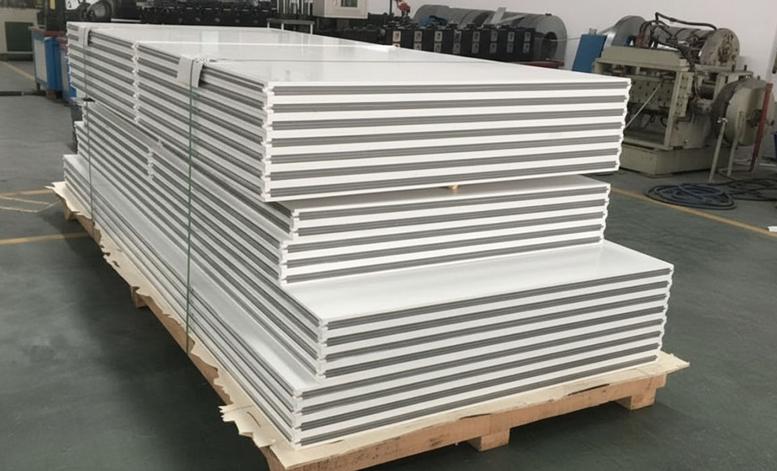
Thermal Expansion Management and Joint Spacing
Composite panels expand differently than pure aluminum. Precise thermal calculations and dynamic joint sealing are mandatory to prevent structural buckling.
Calculating Composite Expansion Dynamics
Composite panels exhibit significantly higher thermal expansion rates than pure aluminum sheets due to their plastic or foam cores. We strictly calculate an expansion rate of approximately 0.24mm per meter for every 10°C temperature shift. This specific metric accounts for the differential movement between the outer metal skin and the inner core material. Ignoring this expansion delta guarantees structural failure in long-span installations.
Maintaining Critical Gap Tolerances
Accommodating calculated thermal movement requires strict adherence to minimum gap tolerances between panels. Installers must maintain a strict minimum gap of 3mm between panels to prevent them from pressing against each other during peak thermal expansion. Without this precise spacing, accumulated internal stress will manifest as visible panel buckling or “oil-canning” on the finished facade. Consistent gap tolerances are a non-negotiable requirement for maintaining a flat, high-end architectural appearance.
How to Choose Dynamic Joint Seals
Standard rigid sealants will crack when the facade moves. We mandate the use of highly elastic EPDM gaskets or premium silicone seals for all dynamic joints. These materials are engineered to stretch and compress continuously as the composite panels expand and contract. This elasticity ensures the joint remains completely weather-tight over the building’s entire lifecycle, protecting the insulation core from moisture intrusion.
Designing Regular Expansion Joints
For massive exterior walls, continuous panels are physically impossible to manage. We design dedicated expansion joints at regular intervals along long facades to act as stress-relief valves. These intentional breaks compartmentalize the thermal movement, preventing it from accumulating uncontrollably across the structure. Properly spaced expansion joints are the final safeguard against catastrophic facade distortion.
| Parameter | Specification | Management Technique | Performance Benefit |
|---|---|---|---|
| Thermal Movement Rate | Thermal movement rates dictate the precision required in subframe alignment and panel sizing. For every 100°C temperature change, materials experience an approximate cumulative expansion of 2.3 mm per meter length. | Calculate precise expansion gaps during subframe alignment and panel sizing | Prevents panel buckling, warping, and structural instability |
| Mounting Hardware | Adjustable sliding clips with predefined lateral movement slots | Secure panels firmly while allowing unimpeded lateral movement | Accommodates expansion and contraction without inducing mechanical stress |
| Joint Spacing & Sealing | Joints equipped with sealing tapes and compressible gaskets | Apply flexible sealants that adapt dynamically to dimensional changes | Maintains long-term weather tightness and prevents joint cracking |
| Material Properties | Low thermal conductivity combined with inherent material flexibility | Leverage material composition to naturally absorb and dissipate heat | Protects surface finish and maintains structural integrity during heat cycles |
| Climate Resilience | Advanced surface coatings integrated with flexible joint design | Design system to withstand extreme seasonal and diurnal temperature swings | Ensures reliable performance and enhanced energy efficiency in extreme climates |
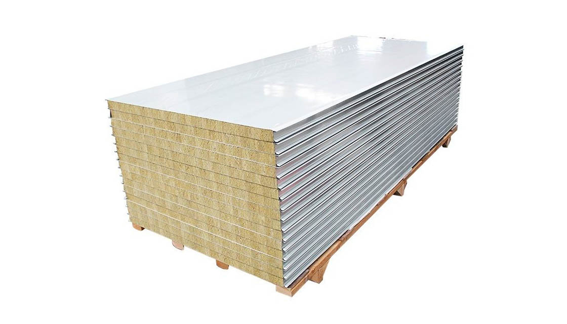
Sealing Techniques and Weatherproofing Protocols
Effective sealing prevents water ingress and protects the facade. We distinguish between open-joint rainscreens and wet-sealed systems to ensure long-term durability.
Open-Joint Rainscreen vs. Wet-Sealed Systems
How to Choose the right sealing protocol depends entirely on the building’s climate and architectural design. Open-joint rainscreen systems rely on geometry and gravity to shed water, using ventilated cavities to manage moisture pressure. This method requires precise fabrication of panel joints to ensure consistent drainage paths.
Conversely, wet-sealed systems depend on continuous bead application of high-grade sealants to create a watertight barrier. While effective, this approach places immense demand on the sealant’s ability to handle dynamic building movements without tearing. Our engineering team evaluates both methods against local wind and rain loads to recommend the most resilient configuration for your specific project.
Ensuring Continuous Moisture Barriers
Water ingress behind panels causes irreversible damage, including subframe corrosion and core saturation. To prevent this, installers must establish a continuous moisture barrier that bridges all panel edges and penetrations. Any interruption in this barrier creates a capillary pathway for water to infiltrate the building envelope.
- Joint Sealing: Apply backer rods to control sealant depth and prevent three-sided adhesion, which leads to premature failure.
- Cavity Management: Install weather-resistant barriers behind the subframe to catch any water that bypasses the outer cladding layer.
- Penetration Details: Use specialized flashing and sealants around windows and corners to maintain the continuity of the moisture barrier.
Testing Sealant Compatibility with ACP Coatings
Not all sealants are chemically compatible with aluminum composite panel (ACP) coatings. Solvent-based sealants can migrate into PVDF or HPL finishes, causing permanent staining, softening, or premature chalking of the surface.
Before full-scale installation, we mandate compatibility testing. Our lab verifies that the chosen sealant does not react adversely with the specific coating chemistry of our panels. This step ensures that the aesthetic integrity of the facade remains intact for decades, protecting your investment from costly cosmetic failures.
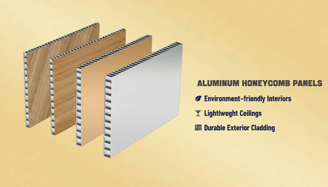
Common Installation Errors and Structural Consequences
Installation errors cause irreversible structural failure. Avoid mechanical distortion, moisture entrapment, and chemical incompatibility to protect facade integrity.
Avoiding Fastener Distortion
Over-tightening mechanical fasteners is a critical error that compromises both the aesthetic and structural integrity of the cladding. When installers apply excessive torque to face-fixed screws, the localized stress exceeds the yield strength of the aluminum skins, causing permanent dimpling or “oil-canning” across the panel surface.
This distortion is not merely cosmetic; it indicates that the panel is under constant tension, which can lead to fatigue cracks around the fixing points over time. To prevent this, strict torque limits must be enforced during the mechanical fixing phase, ensuring the panels sit flush against the subframe without being crushed by the mounting hardware.
Identifying Trapped Moisture
Improperly sealed joints allow ambient humidity and rainwater to penetrate the cavity behind the facade. Once inside, this moisture becomes trapped against the building’s structural substrate, leading to severe consequences such as concrete spalling, steel reinforcement corrosion, and mold proliferation within the wall assembly.
Contractors must vigilantly inspect joint seals for continuity. Signs of failure include bubbling paint on interior walls, efflorescence on the exterior, or a persistent damp smell. Our engineering team emphasizes that a properly executed rainscreen system requires a continuous, unbroken moisture barrier behind the composite panels to prevent these costly retrofits.
Correcting Subframe Misalignment
A facade is only as flat as the subframe supporting it. If the underlying steel or aluminum structure is installed out of tolerance, the composite panels will inevitably follow these irregularities, resulting in an uneven, wavy facade plane that ruins the architectural vision.
To mitigate this risk, rigorous laser leveling must be performed during the subframe installation phase. Any deviations must be corrected using adjustable shims or leveling brackets before the first panel is mounted. We have found that investing time in precise subframe alignment eliminates the need for expensive corrective measures after the cladding is already in place.
Mitigating Core Degradation
Using sealants or adhesives incompatible with the panel’s core material is a silent killer of facade longevity. Solvents found in certain low-quality caulks can chemically attack the polyethylene (PE) or PVC cores, causing delamination or melting from the inside out.
It is imperative to verify the chemical compatibility of all sealing materials with the specific core composition of the panels being installed. For our high-performance composite panels, we strictly recommend using neutral-cure silicones specifically formulated for use with composite cores to ensure long-term adhesion and core stability.
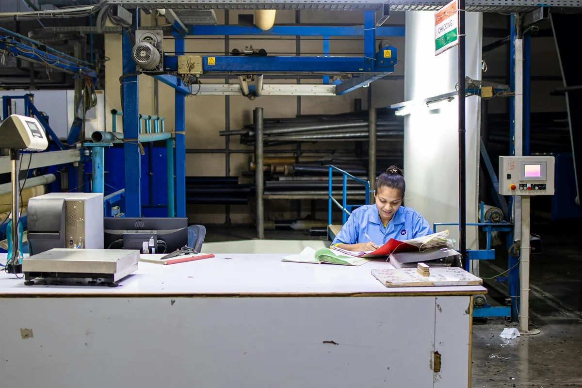
Quality Assurance and Final Inspection Standards
Final inspection is the critical last line of defense against facade failure. Rigorous pre-closure testing and careful documentation protect your liability.
Conducting Pull-Tests on Adhesive Bonds Before Full Facade Closure
In our experience with advanced composite panels, adhesive integrity is the most vulnerable point in any installation. Unlike traditional materials, Rax Panel’s lightweight solutions rely heavily on proper bonding, making pull-tests non-negotiable. We require our engineering teams to perform destructive pull-tests on sample assemblies before proceeding with full facade closure. This step ensures that the adhesive system selected for the specific core material—whether it’s a foam core or a honeycomb structure—achieves the necessary shear strength.
Skipping this verification can lead to catastrophic delamination, especially in high-wind zones. By validating the bond between the facing and the core, we eliminate the risk of hidden failures that only become apparent after the building is enclosed. This proactive measure safeguards the structural performance of the composite panel system.
Inspecting Joint Widths for Consistency and Proper Gasket Seating
Joint consistency is critical for maintaining the weatherproofing and aesthetic integrity of the facade. During final inspection, we carefully verify that all joint widths match the design specifications within a tolerance of ±1mm. Any deviation can compromise the seating of the EPDM gaskets or silicone seals, leading to potential water ingress.
Proper gasket seating is equally important. We inspect each joint to ensure that the gaskets are fully compressed and seated correctly within the channel. Loose or misaligned gaskets can allow wind-driven rain to penetrate the assembly, causing damage to the building envelope and the composite panels themselves. Consistent joint widths ensure a uniform appearance and reliable performance.
Removing Protective Films Immediately to Prevent Adhesive Residue Buildup
Protective films on composite panels must be removed promptly after installation. Leaving them on for extended periods, especially under UV exposure, can cause the film to bond permanently to the surface. This results in difficult-to-remove adhesive residue that can damage the panel’s coating and finish.
Immediate removal prevents this issue and ensures the panels maintain their intended aesthetic appeal. Our technicians are trained to strip the films carefully, checking for any adhesive transfer and cleaning the surface if necessary. This step is crucial for preserving the quality and longevity of the composite panel system.
Documenting Installation Steps for Warranty Validation and Liability Protection
Comprehensive documentation is essential for validating warranties and protecting against liability claims. We require detailed records of every installation step, including photos of the substrate preparation, adhesive application, panel mounting, and joint sealing. This documentation serves as proof of proper installation and compliance with manufacturer guidelines.
In the event of a dispute or failure, this record provides clear evidence of the installation process. It helps distinguish between manufacturing defects and installation errors, ensuring that valid warranty claims are honored while protecting against fraudulent ones. Thorough documentation is a best practice that benefits all parties involved in the project.
Key Takeaways
The points above cover the core decisions. What matters most is matching specifications to your actual operating conditions rather than defaulting to generic recommendations.
Frequently Asked Questions
This factor has a direct bearing on project performance and long-term cost. Addressing it with specific data rather than general assumptions leads to better outcomes.
Are ACPs fire-resistant or combustible?
ACP flammability depends entirely on the core material used during manufacturing. Standard ACPs with polyethylene cores are combustible and may not meet strict fire codes for high-rise buildings. Fire-retardant cores, such as mineral-filled or A2-grade non-combustible materials, are available for enhanced safety. Always verify the fire rating classification required by local building codes before selection.
How long do ACPs typically last?
High-quality aluminum composite panels typically last between 20 to 30 years depending on environmental conditions and coating type. Premium coatings like PVDF offer superior resistance to UV radiation, fading, and chalking compared to standard polyester finishes. Regular maintenance and proper installation significantly extend the lifespan of the cladding system. Exposure to extreme coastal or industrial environments may require more frequent inspections.
Can ACP be modified on-site?
Yes, ACP can be cut, drilled, and bent on-site using standard woodworking or metalworking tools. However, cuts should be made with fine-tooth blades to prevent chipping the aluminum skin. Exposed core edges must be sealed immediately to prevent moisture ingress and delamination. Complex shapes or large modifications are often better suited for factory fabrication to ensure precision and quality control.
How should ACP be stored before installation?
Aluminum composite panels must be stored indoors in a dry, ventilated environment to prevent moisture damage and corrosion. Panels should remain in their original protective packaging until the moment of installation to avoid surface scratches or chemical exposure. If outdoor storage is unavoidable, ensure the area is covered and elevated off the ground to prevent water accumulation. Proper storage preserves the integrity of the gel coat and core materials.
What is the best way to clean ACP?
Clean aluminum composite panels using a soft cloth or sponge with mild soap and warm water. Avoid abrasive cleaners, steel wool, or harsh solvents that can damage the protective coating or finish. Rinse thoroughly with clean water to remove any soap residue that could cause streaking. Regular cleaning prevents the buildup of dirt and pollutants, maintaining the aesthetic appeal of the facade.