
In modern high-rise architecture, institutional infrastructure, and commercial facades, building envelope engineers constantly balance structural dead-load limits against exterior wind resistance. Standard solid metal plates or heavy masonry panels add excessive gravity loads to concrete superstructures, complicating subframe cantilever engineering. Deploying architectural aluminum composite panel systems—commonly specified as architectural aluminum composite facade panels—delivers installed dead loads of only 5.5 to 7.5 kg/m² while matching the flexural rigidity of 3.0 mm solid aluminum. However, capturing these structural advantages requires rigorous engineering: calculating wind suction deflections, preventing chimney-effect cavity fire propagation, and avoiding severe grooving fractures during tray fabrication.
In our architectural facade production facility, our engineering team manufactures and fabricates tens of thousands of square meters of engineered composite cassettes every month for commercial towers, airport terminals, and healthcare facilities worldwide. We operate multi-axis CNC routing centers and automated continuous hot-press lamination lines, processing heavy-gauge 0.50 mm architectural skins bonded to mineral-filled fire-retardant and non-combustible core matrices. Every production run undergoes rigorous laboratory qualification, validating structural wind load deflection under ASTM E330, certifying multi-story flammability resistance under NFPA 285, and issuing factory quality signoffs traceable to primary coil lots. Mastering core material physics, subframe wind anchoring, and perimeter cavity fire stops enables envelope contractors to deliver durable, code-compliant building exteriors.
Why Composite Architecture Lowers Facade Structural Weight
The structural efficiency of aluminum composite material stems directly from its optimized I-beam cross-sectional physics. In traditional monolithic aluminum sheets, flexural rigidity depends solely on overall sheet thickness, meaning that doubling rigidity requires doubling metal mass and material expense. An architectural composite panel distributes material mechanically where stresses concentrate during positive wind pressures and negative suction forces: placing high-tensile 0.50 mm aluminum skins at the extreme outer fibers while bonding them to a lightweight thermoplastic or mineral-filled polymer core.
This sandwich configuration generates an exceptional flexural rigidity (EI value) of approximately 0.125 to 0.240 kN·m²/m for standard 4.0 mm panels, rivaling 3.0 mm solid aluminum plate while reducing overall weight by over 40%. Lower panel dead load translates directly into substantial structural savings across the building frame: lighter primary columns, smaller foundation footings, and reduced secondary subframe steel requirements. For mid-rise and high-rise commercial structures located in seismic activity zones, lower facade mass dramatically decreases lateral inertia forces calculated during structural seismic load modeling.
The structural core acts as an acoustic and thermal buffer, dampening high-frequency acoustic vibrations and rain drumming noise that frequently afflict thin solid metal rainscreens. When specifying composite envelopes, facade teams must calculate skin thickness and core properties just as carefully as structural engineers classify fire-rated composite panels under local life-safety building codes.
Beyond weight reduction, composite panels provide remarkable acoustic deadening. The viscoelastic polymers within the core dissipate vibrational energy created by urban traffic and exterior winds, providing a Sound Transmission Class (STC) rating between 26 and 30 dB. This acoustic damping creates quieter interior workspaces compared to uninsulated sheet metal facades.
Classify Core Fire Ratings Under NFPA 285
Material core chemistry represents the single most critical specification decision in modern facade engineering. Historical reliance on low-density polyethylene (LDPE) core materials resulted in catastrophic multi-story facade fires when combustible cores ignited and fueled rapid exterior flame spread. Modern international building codes mandate strict fire classification based on comprehensive testing standards.
Core formulations fall into three distinct commercial categories. Standard Polyethylene (PE) cores contain 100% thermoplastic resin; while lightweight and highly ductile, their high calorific value restricts their deployment to low-rise single-family residential projects or single-story commercial canopies under twelve meters in height. Class B1 Fire-Retardant (FR) cores incorporate approximately 70% non-combustible mineral fillers (primarily aluminum trihydrate, ATH) within a polyethylene binder, releasing bound water vapor when heated to suppress combustion.
For high-rise commercial towers and institutional facilities exceeding three stories, specifications mandate Class A2 non-combustible cores containing over 90% mineral compounds. High-rise installations in North America must prove compliance with full-scale assembly testing under NFPA 285 multi-story exterior wall flammability standards, confirming zero vertical or lateral flame propagation across building stories.
Compare Cassette Trays Against Face Fastened Riveting
Selecting the attachment method dictates both architectural appearance and long-term envelope maintenance requirements. The two predominant mounting systems specified by facade consultants are concealed hanging cassette trays and exposed face-fastened riveting.
Concealed cassette tray systems represent the gold standard for high-end commercial architecture. Fabricators rout and fold flat composite sheets into 25 mm to 50 mm deep pan cassettes, reinforcing perimeter returns with extruded aluminum profiles. The cassettes hang from concealed aluminum bracket clips fastened to vertical mullions. This floating attachment allows unrestrained thermal expansion and contraction without generating visible oil-canning waviness across large panel faces.
In contrast, exposed face-fastened systems attach flat, unfabricated composite sheets directly to subframe profiles using color-matched stainless steel or aluminum rivets. While face riveting reduces workshop fabrication labor by 30% to 40%, fastener heads remain visible, and over-tightened fasteners can lock thermal movement, causing localized panel buckling. Review this engineering comparison to select the optimal attachment approach for your project envelope.
| System Parameter | Concealed Hanging Cassette Tray | Exposed Face-Fastened Riveted |
|---|---|---|
| Architectural Aesthetics | Clean monolithic surface; zero visible mechanical fasteners | Visible fastener heads along panel margins at 300 mm pitch |
| Thermal Expansion Accommodation | Free-floating bracket engagement; zero thermal oil-canning | Requires oversized rivet pilot holes to permit sliding |
| Wind Suction Capacity (ASTM E330) | Up to 4.5 kPa with perimeter extruded hook clips | Up to 3.2 kPa limited by rivet head pull-through shear |
| Shop Fabrication Complexity | Moderate; requires CNC V-grooving and corner riveting | Minimal; rectangular cutting and perimeter hole drilling |
| Recommended Building Type | High-rise towers, corporate headquarters, airport facades | Low-rise industrial parks, retail boxes, retrofit canopies |
Accommodating thermal linear expansion is critical for long-term facade flatness. Aluminum alloys exhibit a linear thermal expansion coefficient of approximately 2.4 mm per meter across an 80°C seasonal temperature variation (-20°C in winter to +60°C under direct summer solar radiation). On a continuous twenty-meter facade run, cumulative thermal movement exceeds 48 mm. Concealed cassette clip brackets absorb this kinetic displacement effortlessly through slotted anchor holes and low-friction nylon slide bushings, maintaining crisp, uniform panel reveals across decades of seasonal cycling.
For contractors planning in-house processing of composite panels, mechanical cutting tools and blade configurations should be coordinated with the technical parameters outlined in our guide on how to cut aluminum composite panels.
Engineering Pressure Equalized Ventilated Rainscreen Cavities
High-performance composite facades operate on the thermodynamic principle of pressure-equalized rainscreen design. Rather than attempting to create a perfectly sealed exterior barrier with wet caulking—which inevitably degrades under thermal cycling and ultraviolet radiation—rainscreen systems manage moisture through controlled air circulation and gravity drainage.
The system incorporates three primary functional layers: an outer decorative composite cladding leaf featuring open joints, an unobstructed 25 mm to 50 mm ventilated air cavity, and an inner weather-resistant barrier (WRB) applied directly over the backup wall substrate. When high-velocity wind strikes the facade, air enters the cavity through perimeter reveals, equalizing cavity air pressure with exterior wind pressure in milliseconds. Eliminating pressure differentials removes the primary mechanical driving force that pushes wind-driven rain into wall cavities.
To certify structural performance, the complete facade assembly undergoes rigorous testing under ASTM E330 structural wind load testing standards. Facade specifications enforce strict deflection limits: structural subframe mullions must not deflect beyond L/175 of the span, while composite panel center deflection must remain strictly within L/60 under peak design wind suction pressures.
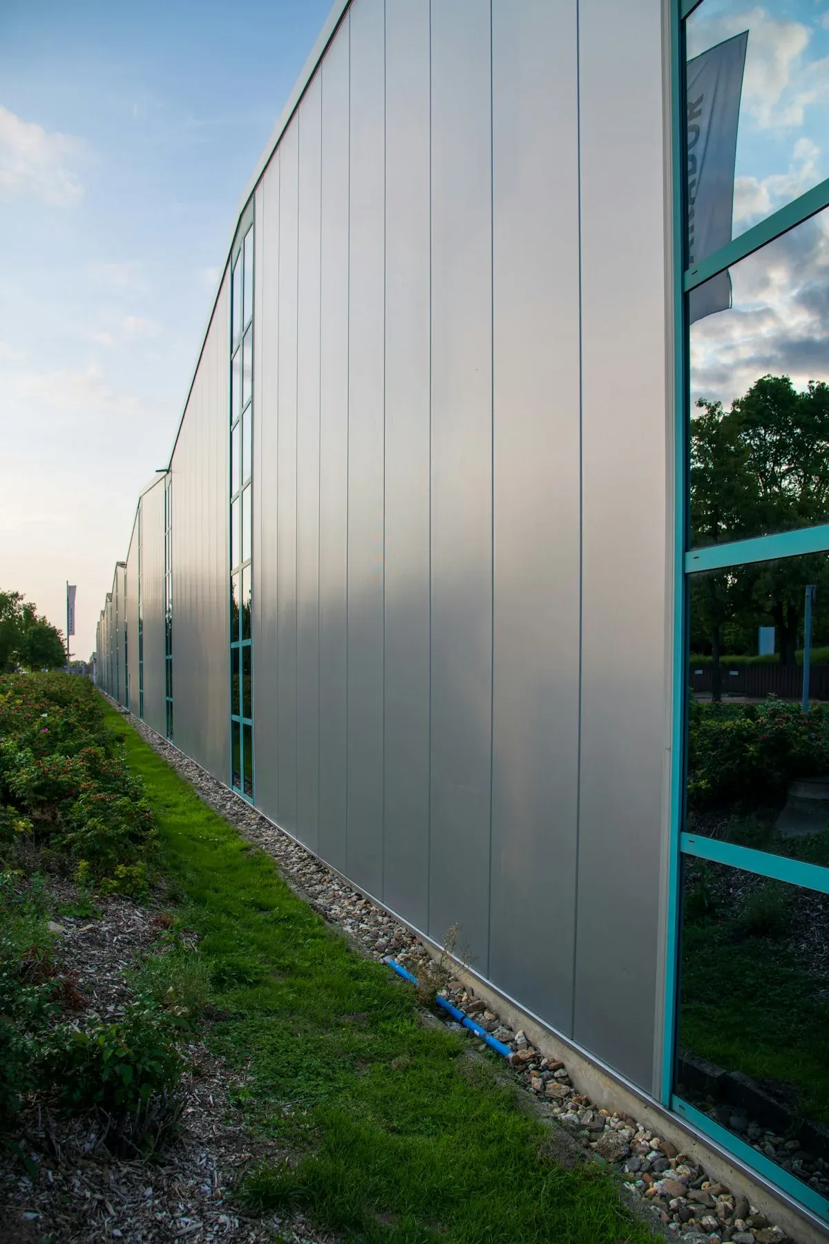
In addition to pressure equalization, thermal buoyancy drives continuous natural convection within the cavity. Warm air rises and vents out through top parapet flashings, continuously expelling condensation and moisture that penetrates the outer skin. This continuous airflow prevents mold formation across structural insulation boards and protects backup framing from long-term moisture rot.
Fabricating CNC Routed Cassettes With Precision Grooves
Transforming flat composite sheets into rigid 3D architectural cassettes requires specialized CNC routing machinery and disciplined tooling geometry. Fabricators execute folding operations by machining continuous V-shaped grooves along the rear panel skin, removing the inner aluminum sheet and the majority of the polymer core while leaving the outer aluminum skin completely undisturbed.
Grooving geometry dictates folding success. For standard 90-degree cassette corner returns, technicians deploy 90-degree V-grooving cutters configured to leave a residual core thickness of exactly 0.8 mm to 1.0 mm atop the 0.50 mm front aluminum face. If the cutter cuts too shallow and leaves excess core material, the radius becomes too tight, causing the outer aluminum skin to stretch and crack during manual folding. Conversely, if the router penetrates too deep and scores the outer aluminum face, the panel fractures instantly along the fold line when exposed to coastal wind gusts.
Following CNC grooving, technicians fold the panel perimeter returns upward into rigid cassette trays. Corners are reinforced with heavy-gauge aluminum corner angles riveted to both vertical and horizontal returns. For panels spanning wider than 1,000 mm, extruded aluminum stiffener ribs are bonded to the rear panel face using high-modulus structural silicone or double-sided acrylic foam tape, preventing oil-canning drum effects under dynamic wind suction.
For oversized cassette trays exceeding 1,200 mm by 2,400 mm in panel dimensions, wind suction forces generate significant center deflection that cannot be resisted by perimeter returns alone. Structural engineers specify extruded aluminum top-hat stiffener profiles bonded vertically along the panel centerline. The stiffeners are adhered to the rear aluminum skin using high-shear structural acrylic foam tape paired with two-component polyurethane adhesives, transferring center wind loads directly into perimeter brackets without telegraphing visible glue lines through to the front facade surface.
4 Costly Mistakes in ACP Cladding Installation
Routing Through Inner Aluminum Skins During Grooving
Permitting machine operators to cut V-grooves without continuous depth calibration causes tool bits to score the outer 0.50 mm aluminum skin. Once scored, the structural tensile capacity of the outer aluminum sheet drops by over 80%. When coastal storms apply negative suction pressure to the facade, panels snap along grooved edges and detach from the building. CNC vacuum tables and floating routing heads must maintain a consistent 0.8 mm residual core thickness across entire sheet lengths. For the decision side of that choice, this why-choose guide to aluminum curtain walls ranks the reasons that hold up.
Omitting Intumescent Cavity Barriers Across Floor Levels
Leaving the continuous 38 mm ventilated cavity unsegmented between floor slabs creates a vertical chimney flue that accelerates smoke and flame spread during building fires. In multi-story commercial construction, building codes mandate horizontal ventilated fire cavity barriers installed at every floor line. These barriers incorporate high-expansion intumescent graphite strips that expand tenfold when exposed to heat above 180°C, sealing cavity air gaps within ninety seconds.
Fastening Aluminum Cassettes Directly to Uninsulated Steel
Fixing aluminum bracket clips directly onto cold-formed galvanized steel wall studs without dielectric isolation creates an electrochemical galvanic couple. Moisture inside the ventilated cavity acts as an electrolyte, causing the aluminum brackets to corrode sacrificially against the steel studs. Installers must place vulcanized EPDM rubber pads or high-density polyethylene shims behind every wall bracket to permanently isolate dissimilar metals.
Applying High Plasticizer Acid Sealants on Fluoropolymers
Sealing panel expansion joints with standard commercial acetoxy silicone sealants containing volatile organic plasticizers results in severe facade streaking. Over twelve to twenty-four months of ultraviolet exposure, plasticizers migrate out of the sealant and deposit onto surrounding PVDF coatings, creating unsightly brown streaks that permanently etch fluoropolymer finishes. Specifications must mandate non-staining, 100% neutral-cure silicone sealants certified to ASTM C1248 standards.
Engineered Architectural Aluminum Composite Facades
Designing commercial towers, civic transit hubs, or institutional envelopes requiring verified lightweight performance and full NFPA 285 fire safety compliance? Our architectural cladding division manufactures high-performance 4.0 mm and 6.0 mm aluminum composite cassettes with certified Class A2 and B1 mineral cores. We supply custom color-matched AAMA 2605 PVDF finishes, precision CNC routing packages, and complete structural subframe engineering support for facade contractors worldwide.
Frequently Asked Questions About Composite Facades
What is the primary structural benefit of ACP cladding?
ACP cladding provides an ultra-light dead load of 5.5 to 7.5 kg/m² while matching the flexural rigidity of 3.0 mm solid aluminum plate, reducing building foundation costs.
Which core material is required for high-rise commercial buildings?
High-rise commercial buildings require Class A2 non-combustible mineral cores containing over 90% inorganic compounds, verified through full-scale NFPA 285 multi-story fire testing.
Why is cassette tray hanging preferred over exposed riveting?
Concealed cassette trays allow unrestrained thermal expansion along sliding clip brackets, completely eliminating visible mechanical screw heads and preventing thermal oil-canning waviness.
How deep should CNC V-grooves be routed for panel folding?
Cutter bits must leave exactly 0.8 mm to 1.0 mm of residual core atop the 0.50 mm outer skin, preventing skin cracking during bending or fracture under storm loads.
How do ventilated rainscreens manage wind-driven rainwater?
Air enters the 25 mm rear cavity to equalize internal and external wind pressures in milliseconds, eliminating the pressure differentials that drive water through wall seams.