
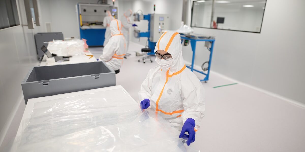
A maioria dos planejadores de instalações assume painéis para sala limpa serem apenas revestimentos de parede genéricos até que o teste de estanqueidade ao ar falhe durante o comissionamento. A realidade é que os painéis de sala limpa comportam-se como componentes estruturais de construção, onde a seleção do material da face e a densidade do núcleo determinam diretamente a tolerância de instalação e a conformidade sanitária a longo prazo. Ignorar a preparação adequada da superfície ou desconsiderar a química do selante com revestimentos compostos cria microvazios que comprometem as diferenças de pressão, independentemente de quão caro o sistema de filtros acabe sendo. Este guia presume uma construção nova; a versão para instalação no local existente é abordada em como modernizar uma sala limpa existente no local.
Considere esta restrição técnica específica das especificações do fabricante: a capacidade de carga do teto para circulação exige suporte estrutural mínimo de 40 lb/ft² integrado à estrutura do painel. Se o seu substrato não suportar esse peso estático mais o tráfego dinâmico de manutenção, as juntas cam-lock sofrerão fadiga em poucos meses. Este artigo abrange os requisitos críticos de preparo do local para planicidade e capacidade de carga, explica por que a compatibilidade do selante é mais importante do que se imagina ao aplicar em aço revestido de uPVC, e detalha como verificar a integridade das juntas antes da integração com HVAC para não perder tempo corrigindo descumprimentos dos limites de contagem de partículas após a instalação.
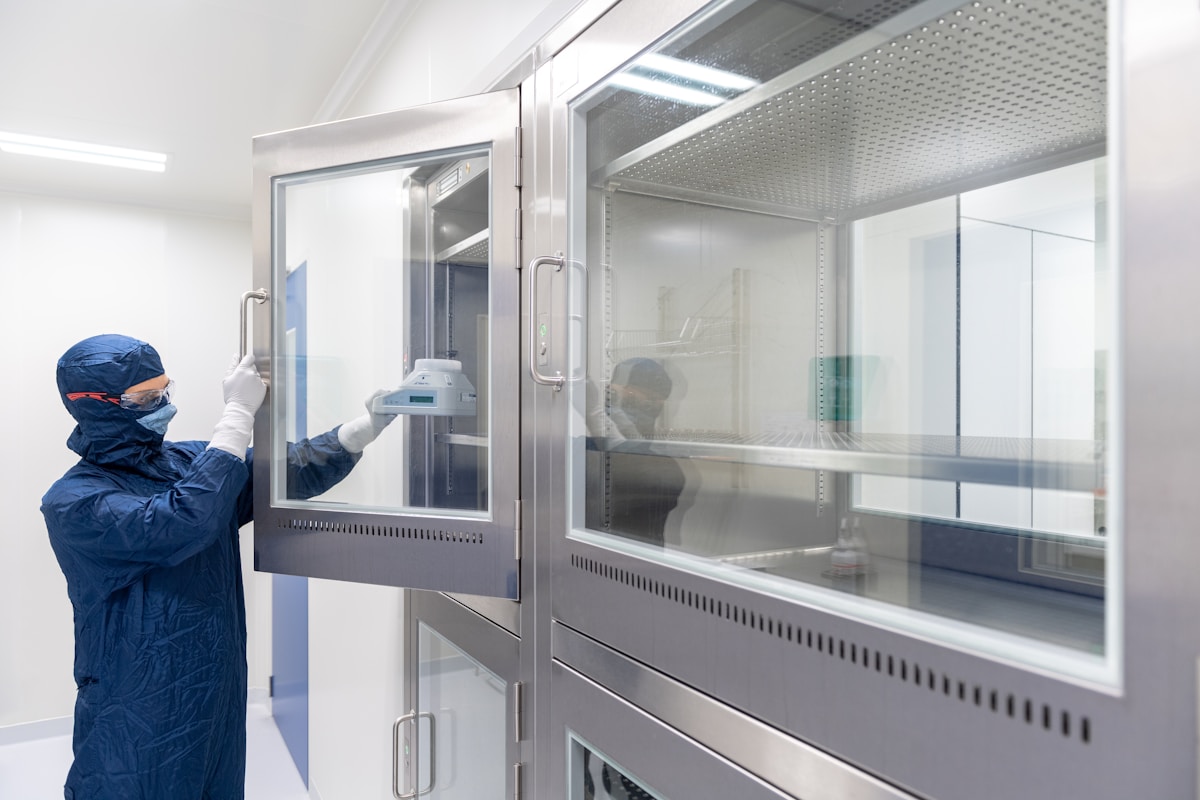
Preparação do Local e Coleta de Ferramentas
Certifique-se de que a base esteja nivelada, a capacidade de carga estrutural seja verificada e a compatibilidade do selante seja conferida antes de iniciar a instalação.
Em construção modular de salas limpas, a preparação da superfície do solo é a base de uma instalação bem-sucedida. Superfícies desiguais ou não preparadas geram problemas significativos de desalinhamento que se propagam para cima pela estrutura dos painéis, afetando o funcionamento das portas e a estanqueidade ao ar. Antes de qualquer painel ser posicionado, certifique-se de que a superfície do solo tenha sido totalmente nivelada e que as utilidades subterrâneas estejam ajustadas para evitar conflitos posteriores durante a montagem. Esta etapa é crucial para prevenir empenamentos estruturais e garantir o alinhamento preciso dos painéis durante toda a construção.
Com base em nossa experiência com milhares de instalações em diferentes setores, constatamos que mesmo pequenas variações no nívelamento do piso podem causar problemas em cascata na instalação de painéis compostos. de alta precisão. A importância desta etapa não pode ser superestimada — não se trata apenas de estética, mas da integridade funcional de todo o sistema da sala limpa.
Antes da instalação, verifique se a estrutura subjacente atende às especificações de carga necessárias para a sua aplicação específica. Isso inclui confirmar que o teto e a estrutura de suporte podem acomodar tanto o peso dos painéis instalados quanto cargas adicionais de pessoal realizando trabalhos de manutenção nas seções superiores.
Para projetos que exigem acesso a unidades de HVAC ou saídas de ar acima dos painéis, é essencial confirmar que essas áreas foram projetadas com capacidade estrutural suficiente. Recomendamos realizar verificações rigorosas logo na fase de planejamento para evitar retificações custosas ou problemas de segurança no futuro. Avaliações adequadas de carga garantem estabilidade a longo prazo e operação segura do ambiente da sala limpa.
Compatibilidade do Selante com Revestimentos Compostos
Ao selecionar selantes para aplicações em juntas entre painéis compostos, sempre correspondê-los especificamente ao material da face escolhido. O uso de selantes incompatíveis pode resultar em falha de aderência, degradação prematura ou reações químicas que comprometem os padrões higiênicos da sala limpa. Diferentes faces — como aço inoxidável, PRFV, alumínio ou PVC — requerem formulações diferentes para manter o desempenho ideal ao longo do tempo.
Nossa equipe de engenharia aconselha consistentemente os clientes a consultar as fichas técnicas fornecidas pelos fabricantes antes de definir as escolhas de selante. Em casos onde múltiplos materiais são utilizados em um único projeto, a consulta cruzada das tabelas de compatibilidade torna-se especialmente crítica. Lembre-se: o que funciona perfeitamente para um tipo de face pode causar problemas com outro. Sempre priorize soluções testadas e aprovadas para garantir resultados duradouros.
| Característica | Especificação | Vantagem |
|---|---|---|
| Preparação do Local | Superfície do solo nivelada, utilidades subterrâneas ajustadas, obras principais de fundação finalizadas | Garante uma fundação estável para alinhamento preciso dos painéis e previne empenamento estrutural |
| Layout Tolerance | Vertical alignment deviation ≤1.0% (max 3mm), ground rail width marked at 50mm | Guarantees precise door/window positioning and seamless panel interlocking |
| Seam Management | Wall panel vertical seams maintained with no gaps >0.2mm and tight closure | Precision seam management is critical for maintaining the required airtightness standards specified in joint sealing integrity protocols. |
| Protection Protocol | Protective films remain intact until final installation and cleaning completion | Prevents surface scratches and damage during transportation and assembly |
| Ceiling Load Capacity | Structural capacity verified to support personnel standing for equipment maintenance | Enables safe access to HVAC units and air outlets without compromising structural integrity |
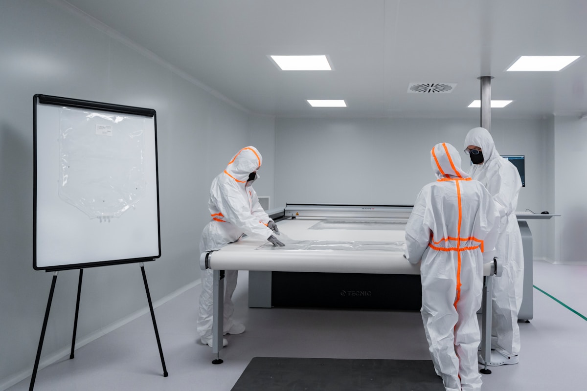
Montagem dos Painéis com Sistemas Cam-Lock
Princípios de Engajamento Mecânico
The cam-lock system operates on a rotary wedge principle to transform rotational force into linear clamping pressure. Unlike conventional screw fasteners that rely solely on thread engagement, a cam-lock utilizes a rotating eccentric cam attached to a connecting rod. When installed through pre-punched mating holes in adjacent panel profiles, a 180-degree rotation of the cam head draws the two panels together. This mechanism effectively eliminates the need for exposed fasteners on the panel surface, maintaining the cleanroom’s required hygienic aesthetic while providing a robust mechanical interlock.
Proper assembly requires the cam to be fully seated in the keeper; partial rotation results in insufficient clamp load and joint failure under pressure differential.
For composite panels featuring rigid facings such as GRP (Glass Reinforced Plastic) or Stainless Steel, the locking action compresses the integrated elastomeric gasket located within the profile’s tongue-and-groove joint. This compression is critical—it creates the air-tight seal necessary for ISO-rated environments while simultaneously transferring shear loads between panels to ensure monolithic wall stability. The system’s design inherently restricts post-installation adjustment; therefore, the alignment must be precise during the initial engagement.
Sequência de Elevação e Estabilidade Estrutural
To achieve structural stability, the erection of cam-lock panels must follow a disciplined sequence beginning from a fixed reference point, typically a corner or an established door frame. Installers must verify the verticality of the first panel using a laser level or spirit level, as any deviation in the initial panel will compound exponentially across the wall run due to the cumulative nature of cam-lock tolerances.
- Vertical Engagement: Engage the vertical cam-locks first, starting from the bottom and working upwards. This ensures the panel is plumb and prevents the weight of the panel from binding the cam mechanism before it is fully seated.
- Horizontal Registration: Once vertical locks are set, slide the adjacent panel into the tongue-and-groove channel. Use a rubber mallet to gently tap the panel into alignment, ensuring the gaskets are flush but not overly compressed before locking.
- Final Locking: Insert the hex key or screwdriver into the cam access port and rotate 180 degrees until resistance is felt. Avoid over-tightening, as excessive torque can strip the cam mechanism or deform lightweight foam cores like XPS or PU.
In ceiling applications, the sequence shifts to ensure load-bearing integrity. Ceiling panels often incorporate a hidden tongue-and-groove system supported by tee-grids. The cam-locks here function primarily to pull the panels tight against the grid, removing deflection. It is imperative that the suspension grid is leveled to within ±1.5mm prior to panel placement; otherwise, the cam-locks will not align, forcing installers to either modify the panels or re-level the grid—both costly errors.
Gerenciamento de Tolerância e Verificação Pré-Instalação
The buyer pain point regarding trade coordination conflicts is acutely felt in cam-lock installations. Unlike drywall or screwed systems, which can be easily disassembled or modified on-site, composite panels with cam-locks are designed as a modular, “drop-in” system. Field modifications—such as cutting a hole for a conduit after the panel is locked—compromise the structural integrity of the profile and the gasket seal.
Failure to pre-coordinate M&E rough-ins: If mechanical and electrical trades do not verify their penetration locations against the panel module dimensions prior to delivery, installers will encounter conflicts where conduit hits a cam-lock location or structural stiffener. Disassembling a locked joint often damages the gasket, requiring replacement parts and delaying the project schedule.
To mitigate this, all service penetrations and cutouts must be pre-engineered at the factory based on verified shop drawings. The modular design of these panels implies that further cutting or processing is not required during installation. When the layout adheres to the factory’s module dimensions, the cam-lock system allows for rapid erection where the structural integrity and air-tightness are guaranteed by the design, not by field improvisation. This pre-fabrication approach is essential for maintaining the strict ISO 14644 cleanliness standards required in pharmaceutical and semiconductor facilities.

Vedação das Juntas para Manter a Estanqueidade ao Ar
Técnicas de Vedação Precisa de Juntas
Achieving an absolute airtight envelope is the primary defense against contamination ingress and thermal loss in controlled environments. Even with high-performance insulation cores like PIR or Rockwool, the system’s efficacy is entirely dependent on the quality of the joint seals. Micro-gaps at panel connections—often invisible to the naked eye—can disrupt critical pressure differentials and allow unfiltered air to bypass the HVAC system. In cleanroom applications specifically, these breaches compromise ISO 14644 compliance by introducing particulate matter directly into the controlled space.
Estratégia de Aplicação de Selante em Dupla Camada
For maximum reliability, best practices dictate a dual-layer sealing approach that secures the joint from both the interior and exterior. Precision-machined tongue-and-groove joint profiles are designed to interlock tightly, reducing the void space to a minimum. However, mechanical connection alone is insufficient. Installers must apply a continuous, uniform bead of neutral cure, cleanroom-grade silicone into the groove joint before the panels are engaged. This internal application creates a gasket-like barrier that maintains air tightness even if the exterior sealant is damaged during future maintenance or rigorous cleaning protocols.
Avoid using acid-cure silicones or standard construction sealants in cleanroom or sterile environments. These materials can outgas volatile organic compounds (VOCs) that contaminate the air supply and degrade sensitive manufacturing processes. Always specify non-outgassing, anti-fungal formulations validated for use with composite facings like GRP or stainless steel.
Vedação de Passagens de Utilidades e Serviços
Utility cutouts for piping, electrical conduits, and ductwork represent the most significant vulnerability in a panel system. These penetrations often create irregular gaps that are difficult to seal with standard beads, becoming persistent sources of leakage. To prevent “bypass airflow” where air moves freely around filters rather than through them, these openings must be managed with rigid sealing boots or specialized grommets. These components must mechanically bond to both the service conduit and the panel facing—whether aluminum, steel, or fiberglass—to ensure the structural continuity of the vapor barrier and thermal envelope.
- Surface Preparation: All joint surfaces must be wiped down with isopropyl alcohol to remove dust and release agents prior to sealant application to ensure optimal adhesion.
- Tooling: Sealant beads must be tooled immediately after application to smooth the profile and force the material into the microscopic texture of the composite facing.
- Curing Time: Respect the full cure time of the sealant before subjecting the joints to pressure testing or cleaning cycles to prevent bond failure.
Conexão de Unidades de HVAC e Filtragem
Vedação de Passagens e Gerenciamento de Fluxo de Ar
The most common failure point in cleanroom integration occurs where utility penetrations intersect the panel surface. Unsealed pipe cutouts act as uncontrolled airflow paths that bypass filtration systems, becoming persistent sources of contamination. Industry standards require that every penetration through composite wall panels be sealed with compatible gaskets or sealants to maintain pressure differentials.
Standard silicone sealants often fail on certain composite facings. The key is selecting a chemically compatible material that bonds permanently without degrading the panel’s surface integrity during thermal expansion cycles.
Montagem de Unidades de Filtro com Ventilador (FFUs)
Proper mounting of Fan Filter Units requires precise load-bearing verification on the supporting structure. When installing FFU brackets on sandwich panels, engineers must ensure the core material can support both the static weight and dynamic vibration loads. For lightweight composite solutions, reinforced backing plates are typically used at mounting points to distribute stress evenly across the panel thickness.
- Vibration Isolation: Use neoprene pads between FFU mounting frames and panel surfaces to prevent structural sound transmission.
- Seal Integrity: Apply continuous bead sealant around FFU flange perimeters before securing fasteners to create an airtight barrier.
- Access Clearance: Maintain minimum 300mm clearance around FFU units for maintenance access without compromising panel sealing.
Protocolos de Conexão de Dutos
Connecting ductwork to panel assemblies requires attention to thermal movement compensation. Metal ducts expand and contract differently than composite panel substrates. Best practices include using flexible connectors or slip joints between rigid duct sections and panel penetrations to prevent stress-induced cracks in the facing material.
For high-humidity environments, specify marine-grade aluminum duct connections with PTFE tape on threads to prevent galvanic corrosion when interfacing with composite panel facings.

Testes Pós-Instalação para Certificação
Post-installation validation is the critical bridge between a physical build and regulatory compliance. Without rigorous testing of airflow, pressure, and seal integrity, even superior composite panels will fail GMP audits.
Teste de Velocidade de Fluxo de Ar e Diferencial de Pressão
Once the modular composite panel walls are fully erected, establishing a stable environment requires more than just sealing joints; you must validate the room’s ability to maintain directional airflow against external pressures. The objective here is to verify that the HVAC system coupled with the panel enclosure achieves the necessary air changes per hour (ACH) while sustaining the required static pressure gradient relative to adjacent corridors or non-classified zones. If your specific application demands a positive pressure differential of +15 Pascals, every square meter of the installed composite surface acts as a variable in this calculation.
In our field experience during pharmaceutical facility validations, we often see contractors measure fan capacity but neglect the back-pressure created by restrictive HEPA filters within the ductwork integrated into the ceiling panels. This mismatch can cause velocity profiles at the workbench to drop below laminar flow thresholds despite the fans running at full speed. Consequently, airflow verification isn’t merely checking if the room is “ventilated”; it involves mapping velocity vectors across the entire workspace to ensure unidirectional flow without dead zones where contaminants might settle before being exhausted.
Validação de Contagem de Partículas por Normas ISO Class
The ultimate metric for cleanroom performance is airborne particulate concentration, which dictates whether your installation meets ISO 14644-1 classification requirements such as Class 5, 7, or 8. After completing structural assembly and confirming pressure differentials, you must perform particle counting using calibrated optical particle counters (OPCs) placed at designated sampling stations throughout the volume of the room. These counts determine compliance based on allowable maximum limits of particles larger than specific micron sizes (e.g., ≥0.5µm or ≥5.0µm) defined in the standard.
When validating environments constructed with Rax Panel’s specialized materials—such as those utilizing smooth GRP facings or stainless steel skins—we note that surface roughness significantly impacts particle shedding potential compared to painted drywall systems. A high-quality composite finish reduces friction-induced electrostatic attraction that typically traps dust on porous surfaces, thereby lowering baseline contamination levels even before active filtration begins to operate. However, this advantage only materializes if seams do not trap migrating particulates from internal adhesives or residual manufacturing debris left post-installation.
Metodologia de Detecção de Vazios na Integridade das Juntas
The most vulnerable points in any sealed container are interfaces—the corners, intersections, and penetrations where two components meet. For composite sandwich panel systems designed for sterile containment, joint integrity leak detection methodology becomes paramount because micro-gaps invisible to the naked eye can permit significant infiltration under negative or positive operating conditions. We recommend employing smoke pencil tests combined with ultrasonic leak detectors to identify discontinuities along vertical and horizontal mullions connecting individual wall units.
“The selection of core materials directly influences fire safety and thermal performance metrics in modular cleanroom construction. Common core materials include PIR for superior thermal insulation (0.022 W/mK) and Rockwool for its Class A1 non-combustible rating versus PIR’s Class B1 self-extinguishing property. Aluminum honeycomb cores offer high strength-to-weight ratios for structural applications. The choice depends on the specific fire safety, insulation, and load requirements of the project.”