
Most facility managers assume refrigeration systems generate cold air. They don’t. These units work by transferring heat from an interior space to the exterior, usually using a mechanical-compression cycle composed of a compressor, condenser, expansion valve, and evaporator. When you view the unit as a heat exchange mechanism rather than a cold box, you stop guessing at parts replacement and start addressing the root cause of the failure.
In a mechanical-compression system, the refrigerant flows through the compressor where its pressure rises, then vaporizes and condenses into liquid while releasing heat. This is the standard configuration for commercial applications, though it fails immediately when heat transfer is interrupted. We explain how to verify insulation integrity and inspect equipment seals before you ever pick up a wrench.
Correct diagnosis lets you distinguish between a simple maintenance issue and a total system failure. Identifying symptoms early—like evaporator coil icing caused by poor heat rejection—prevents costly product spoilage and ensures your installation meets energy efficiency standards.
Check for Structural and Environmental Issues
Before diagnosing mechanical failures, verify the structural envelope. An estimated 30% of perceived refrigeration inefficiency is actually caused by thermal bridging or seal degradation, allowing parasitic heat loads to overwhelm the system.
Inspecting Refrigeration Equipment Seals
Door and panel seals are the primary defense against humidity infiltration, yet they are frequently neglected during routine checks. A failure here forces the compressor to work harder to remove latent heat, leading to short cycling and ice buildup. Technicians should look beyond visual cracks and assess the physical compression of the gasket material. Over time, magnetic rubber gaskets suffer from compression set, losing the resilience required to maintain airtight contact against the frame.
From a structural standpoint, seal integrity is heavily dependent on the flatness and dimensional stability of the mounting surface. If the door frame or adjacent panel has warped due to thermal cycling or impact, even a brand-new gasket will fail. We have observed that using high-density fiberglass or GRP skins in our panel solutions significantly reduces warpage compared to standard metal sheets, ensuring the mounting surface remains true to plane for the lifespan of the seal.
- Compression Test: Close the door on a dollar bill or thin strip of paper at several points. If it slides out without resistance, the magnetic seal is failing to compress sufficiently.
- Clean Contact Surfaces: Inspect the mating surface (the frame or cam-lifter surface) for dirt, rust, or ice buildup that prevents the gasket from seating fully.
- Check for Air Gaps: In dark conditions, use a flashlight around the perimeter of a closed door to spot light leaking through, which indicates immediate pathways for warm air infiltration.
Evaluating Cold Storage Systems Insulation Integrity
The insulation integrity of a cold storage facility is not determined solely by the R-value of the core material but by the continuity of the thermal barrier. Thermal bridging at panel joints is a critical structural risk that mimics mechanical failure.
When metal fasteners or jointing mechanisms penetrate the insulation layer without a proper thermal break, they create a superhighway for heat transfer. This causes the surface temperature to drop locally, resulting in condensation that can freeze and progressively destroy the joint structure.
Pay close attention to corner connections. During our internal stress testing of XPS and PU foam cores, we found that corners are the most susceptible to core compression during installation. If the core is crushed, the thermal resistance effectively drops to zero at that specific point, creating a permanent cold spot that invites mold and rot.
Inspectors must differentiate between surface moisture and deep-seated insulation failure. While surface sweating can often be remedied by improving air circulation, delamination of the panel facings is a severe structural issue. Delamination creates an air gap between the skin and the foam core, acting as a thermal chimney that accelerates energy loss.
In advanced composite panels, such as those we manufacture with CFRT or GRP facings, the bond strength is rigorously tested to prevent this, but field damage from forklift impact can compromise the laminate immediately.
- Thermal Imaging Scan: Use a thermal camera to identify “hot spots” along walls and ceilings. These linear patterns usually indicate missing insulation at studs or joints rather than core failure.
- Joint Inspection: Examine panel-to-panel connections for signs of ice extrusion. If ice is pushing out from the joint, the thermal break has failed and internal moisture is freezing.
- Impact Assessment: Look for dents or punctures in the wall skin. Even a minor impact can crush the foam core behind a metal or GRP face, creating a thermal bridge that persists indefinitely.
Verifying Walk-In Refrigeration System Ventilation
Ventilation in walk-in refrigeration is often misunderstood as unnecessary for a sealed environment. However, proper pressure equalization is vital for structural preservation and safety. Modern cold storage rooms built with high-performance composite panels are exceptionally airtight.
When a door is opened and then closed rapidly, the displacement of air creates a pressure differential. Without adequate pressure relief vents, this pressure can make doors impossible to open from the inside (a safety hazard) or place severe stress on the panel interlocks and door hardware.
Additionally, evaporator units require sufficient airflow to reject heat effectively. If the machinery room or the space above the drop ceiling is poorly ventilated, the waste heat from the condensers can migrate back into the envelope or cause the compressors to overheat. This is particularly relevant in hybrid installations where the refrigeration system is mounted adjacent to or integral to the composite structure.
- Pressure Relief Valves: Ensure that pressure relief vents are installed and not obstructed by storage racks or boxes. These vents allow air to escape when the door closes, preventing structural pressurization.
- Condensate Drain Traps: Verify that drain lines are properly trapped and vented. A dry trap can allow warm, humid air from the drain system to be sucked into the freezer, drastically increasing moisture load.
- Equipment Room Airflow: Check that ventilation fans in the compressor room are operational. Stagnant air around the compressor unit raises the head pressure, reducing cooling efficiency and potentially shortening the equipment’s service life.
| Inspection Focus | Key Structural Risk | Environmental Impact | Maintenance Frequency | Corrective Action |
|---|---|---|---|---|
| Panel Joints & Thermal Breaks | Missing or degraded thermal breaks causing condensation and ice formation | Mold development, slippery floors, and structural integrity loss due to internal icing | Monthly or Quarterly visual inspection | Install insulated battens or cut interior metal skins to restore thermal isolation |
| Compressor & Coil Condition | Dirty coils and low refrigerant forcing compressor beyond design limits | 20-30% increase in energy consumption and accelerated component wear | Every 3–6 months preventive service | Clean condenser coils, verify refrigerant levels, and optimize airflow |
| Temperature Stability & Control | System inability to maintain precise setpoints due to degraded components | Product spoilage, food safety compliance failures, and regulatory risks | Twice a year deep maintenance & calibration | Calibrate sensors and replace worn gaskets or seals to ensure airtightness |
| Overall System Performance Audit | Hidden inefficiencies and reduced equipment lifespan (halving expected 15-20 year life) | Increased carbon footprint and higher total landed cost of ownership | Once a year performance audit | Validate energy efficiency metrics and plan for proactive part replacement |
Safety Steps Before Inspection
Getting specifications right upfront avoids change orders during fabrication. Confirm thickness, facing material, joint type, and dimensional tolerances in writing before production begins.
Lockout Tagout Procedures for Compressors
Before technicians can safely inspect the structural integrity or insulation seals of a refrigerated unit, all mechanical energy sources must be neutralized. Lockout/Tagout (LOTO) procedures are the critical first line of defense, preventing the unexpected energization or start-up of compressors while maintenance is in progress. Compressors store significant kinetic energy and hydraulic pressure; failure to isolate these units can result in catastrophic injury or damage to the composite panels during the inspection process.
The LOTO process requires technicians to identify and shut down all energy isolation points—typically the main disconnect switch for the compressor unit. Once the power is cut, a lockout device must be physically applied to the isolation point, secured with a personal padlock that only the assigned technician possesses.
A tag must then be attached to the lock, displaying the technician’s name, the date, and the reason for the lockout. Crucially, technicians must verify that the equipment is truly de-energized by attempting to start the compressor via the control panel before beginning any work.
Electrical Safety Checks for Control Panels
Control panels serve as the nervous system for cold storage environments, regulating not only temperature but also the defrost cycles that impact panel longevity. Before opening any control cabinet for inspection, technicians must perform a rigorous electrical safety check to mitigate arc flash and electrocution hazards. Even when the main compressor is locked out, control panels may contain multi-source power feeds or capacitors that retain a lethal electrical charge.
A visual inspection of the panel exterior is the first step, looking for cracks, missing screws, or signs of moisture ingress that could compromise the enclosure’s integrity. Technicians must then use a rated non-contact voltage tester to verify the absence of voltage on the exterior of the cabinet before opening the doors.
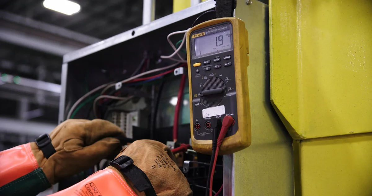
Once opened, a digital multimeter should be used to measure voltage across all phases and terminals to confirm a zero-energy state. Checking the condition of insulation on internal wiring is also essential, as degraded insulation can cause short circuits that may trigger fires, endangering the facility and the composite structure.
Personal Protective Equipment for Technicians
The complex environment of a refrigerated facility demands a comprehensive approach to Personal Protective Equipment (PPE). Technicians are exposed to a unique combination of hazards, including electrical risks, sharp composite materials, and extreme cold temperatures. Standard safety gear is insufficient; PPE must be selected to address the specific threats present during the inspection of insulated structures and their associated mechanical systems.
- Electrical Rated Gloves and Face Shield: When interacting with control panels or near live components, technicians must wear insulated rubber gloves rated for the specific voltage class, paired with a dielectric face shield to protect against arc flash blasts.
- Cut-Resistant Gloves: Handling composite panels, particularly those with fiberglass facings or cut edges, poses a high risk of lacerations and fiberglass irritation. Heavy-duty, cut-resistant gloves are mandatory to ensure safe handling during close-up inspections.
- Thermal Protection: Inspecting panels near evaporator coils or in sub-freezing environments requires thermal insulation. Technicians should wear appropriate cold-weather clothing to prevent hypothermia and loss of dexterity, which is critical for maintaining a safe grip on tools and equipment.
- Anti-Slip Footwear: Condensation and ice buildup on floors near door seals and inspection points create significant slip hazards. Safety footwear with oil-resistant, non-slip soles and toe protection is essential for navigating these wet environments safely.
Spotting Common Signs of Failure
This factor has a direct bearing on project performance and long-term cost. Addressing it with specific data rather than general assumptions leads to better outcomes.
Distinguishing Thermal Envelope Failure from Mechanical Faults
The most pervasive diagnostic error in facility management is attributing thermal anomalies solely to mechanical refrigeration systems. When localized ice formation or sweating appears on panel surfaces, the immediate assumption is often a refrigerant leak or compressor inefficiency.
However, in high-performance insulated structures, these symptoms frequently indicate a breakdown in the thermal envelope continuity. When the compressor short-cycles or runs continuously to maintain setpoints, the root cause may not be mechanical wear but rather a precipitous drop in the assembly’s effective R-value due to structural compromise.
Diagnostic Insight: If the system maintains pressure but exhibits surface sweating, the failure is almost certainly structural—thermal bridging or seal failure—rather than a refrigerant charge issue.
Visual Indicators of Core and Facing Degradation
Surface pathologies such as mold proliferation or persistent moisture accumulation are often misdiagnosed as hygiene failures or humidity control errors. In reality, these are critical visual signals of facing permeability or gelcoat breach. Once the outer skin—whether metal, fiberglass, or high-pressure laminate—is compromised, moisture ingress into the core material begins immediately.
This does not merely cause cosmetic damage; it initiates a chemical breakdown of the bond between the core and the facings. As this adhesive layer fails, the structural integrity of the panel collapses, creating a pathway for thermal energy transfer that renders the insulation layer effectively useless.
Operators must also look for geometric distortions such as bowing or waviness along the panel spans. While often dismissed as aesthetic issues or the result of overloading racking systems, these deformations typically signify core crushing or a loss of flexural strength. When a foam core crushes or a honeycomb structure collapses, the panel loses its ability to resist compressive loads, leading to gaps at joints where air leakage drastically accelerates energy loss.
Auditory and Operational Cues of Insulation Breakdown
Beyond visual inspection, the auditory profile of a refrigeration space can reveal insulation failures. Excessive compressor cycling—the rapid on-off switching of the refrigeration unit—creates a distinct operational rhythm. While this is often blamed on thermostat malfunctions, it is a classic symptom of air leakage through compromised panel seals or joints. When the thermal envelope is breached, the internal temperature spikes rapidly, forcing the compressor to work in short, intense bursts to compensate for the sudden heat gain or loss.
subtle popping or creaking noises during temperature changes can indicate delamination within the composite panel. As dissimilar materials expand and contract at different rates, a weakened bond between the skin and core will shift, producing acoustic evidence of structural fatigue. Ignoring these sounds allows minor delamination to propagate into full-scale core separation, at which point the panel must be replaced entirely rather than repaired.
| Observed Symptom | Common Misdiagnosis | Structural Failure Mode | Technical Impact |
|---|---|---|---|
| Localized Ice Formation on Surfaces | Refrigerant leak or low charge | Thermal bridging at panel joints or metal facings | Localized surface temp drops below dew point; increased thermal transfer |
| Internal Temperature Instability | Compressor wear or thermostat failure | Core delamination or foam cell collapse | Significant reduction in thermal resistance (R-value); loss of insulation continuity |
| Excessive Compressor Cycling | Control system malfunction | Air leakage through compromised panel seals or joints | Increased heat gain/loss rates (ACH50 spike); higher energy load |
| Surface Mold or Moisture Accumulation | HVAC humidity control failure | Facing permeability or gelcoat breach (GRP/FRP) | Moisture ingress into core material; degradation of structural bonds |
| Structural Bowing or Deformation | Overloading by stored goods | Loss of flexural strength or core crushing | Reduced load-bearing capacity; compromised thermal seal integrity |
Inspecting Condensers and Evaporators Visually
Getting specifications right upfront avoids change orders during fabrication. Confirm thickness, facing material, joint type, and dimensional tolerances in writing before production begins.
Surface Contamination and Fins
A thorough visual inspection begins with the physical state of the coils. Inspectors must look for heavy buildup of dirt, dust, grease, or ice on the fin surfaces. This debris acts as an insulator, significantly reducing the heat transfer efficiency required for the system to maintain temperature. When fins are clogged, the condenser cannot reject heat effectively, leading to high head pressure and potential compressor overheating.
Frost Accumulation Patterns
For evaporator units, frost distribution is a critical diagnostic indicator. In a properly functioning refrigeration cycle, frost should ideally form evenly along the bottom rows of the coil where the coldest refrigerant enters. However, if frost builds up unevenly—clumping heavily in the middle or upper sections while leaving other areas clear—it typically indicates low refrigerant charge or a restricted flow issue within the capillary tube or expansion valve.
- Uniform Frost: Indicates healthy refrigerant flow and proper metering.
- Uneven/Icy Blocks: Suggests undercharge, blockage, or airflow restriction.
- No Frost: If the unit is running but coils remain dry and warm, the system may have a complete refrigerant leak.
Physical Damage and Airflow
Inspectors must also check for mechanical damage to the aluminum fins. Bent or crushed fins restrict the volume of air passing through the coil, creating localized hotspots that degrade performance. Ensuring the coils are straight and unobstructed allows for optimal thermal exchange. Furthermore, any visible oil stains near the connections often indicate active refrigerant leaks, requiring immediate attention before a full system failure occurs.
Fixing Temperature Irregularities Step by Step
This factor has a direct bearing on project performance and long-term cost. Addressing it with specific data rather than general assumptions leads to better outcomes.
Diagnosing the Core Insulation Failure
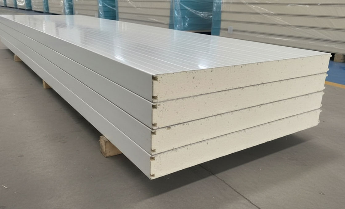
Temperature irregularities within a refrigerated enclosure are rarely caused by mechanical failure alone; they are predominantly the result of compromised structural insulation. When a composite panel’s foam core—such as Polyurethane (PU), Polystyrene (XPS), or Polyisocyanurate (PIR)—undergoes physical damage, the internal cellular matrix is breached.
This breach allows ambient heat to bypass the thermal barrier and introduces moisture into the core, drastically reducing the panel’s R-value. As an industry insider, I consistently see operators misdiagnose uneven cold spots as refrigerant issues when the root cause is a fractured structural skin or a delaminating foam layer.
- Skin Delamination: The separation of the outer fiberglass or aluminum skin from the inner core creates air pockets that act as thermal bridges.
- Impact Fractures: Forklift collisions create micro-fractures in XPS or PVC cores that allow air exchange without visible exterior damage.
- Moisture Saturation: In humid climates, compromised panel seals draw in water, which conducts heat roughly 24 times faster than air, rapidly destabilizing internal temperatures.
📋 Actionable Steps for Thermal Isolation
- Step 1: Perform a Tap Test. Use a rubber mallet to lightly tap suspected zones. A solid “thud” indicates a healthy core, while a hollow or “dull” sound signifies delamination or void formation within the sandwich structure.
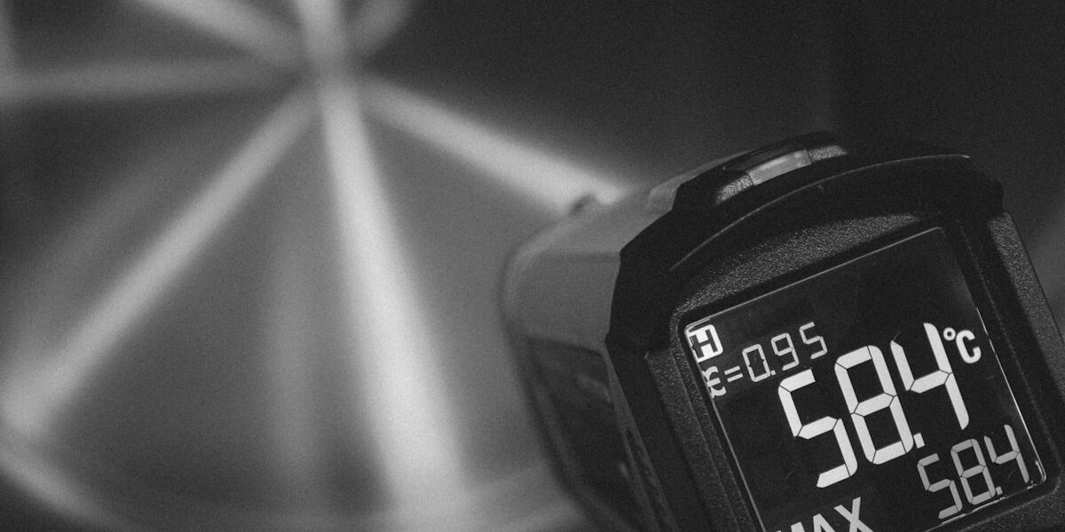
- Step 2: Conduct a Thermal Scan. Utilize an infrared thermometer to map surface temperatures across the wall panels. Identify any localized anomalies (a delta of more than 5°F to 8°F compared to surrounding surfaces) that reveal cold bridges.
- Step 3: Verify Sealant Integrity. Inspect all perimeter seams, door frames, and utility penetrations. Even high-performance PU or PET foam cores will fail if the outer sealing gaskets have degraded, allowing warm, humid air infiltration.
Do not apply a universal fix to all panel types. An Aluminum Composite Panel (ACP) with a PE core requires completely different repair protocols than a Fiberglass Reinforced Plastic (FRP) panel with a PMI or PVC foam core. Misidentifying the facing material during thermal repair can lead to chemical incompatibility and immediate secondary failure.
Evaluating Refrigerant Cycle Efficiency
Once the structural integrity of the enclosure is verified, attention must shift to the mechanical refrigeration cycle. Temperature irregularities frequently stem from a breakdown in the standard vapor-compression loop, where pressure and temperature drops fail to synchronize with the actual heat load inside the insulated space. If the unit struggles to maintain setpoints despite a pristine composite shell, the fault lies within the four fundamental components: the compressor, condenser, expansion valve, and evaporator.
The expansion valve acts as a critical restrictor, converting high-pressure subcooled liquid into low-temperature liquid particles. If this metering device malfunctions, it disrupts the precise phase change required for effective cooling.
A faulty valve causes insufficient liquid refrigerant to reach the evaporator, leading to a loss of cooling capacity and subsequent temperature spikes in specific zones of the walk-in unit. Operators must verify that the low-pressure suction lines are drawing the correct amount of vaporized refrigerant back to the compressor to restart the cycle efficiently.
- Refrigerant Pressure Mismatch: Improper charge levels prevent the refrigerant from vaporizing fully in the evaporator, leaving cooling potential on the table.
- Expansion Valve Blockage: Contaminants in the system can clog the metering device, starving the evaporator of the subcooled liquid needed to absorb ambient heat.
- Compressor Suction Issues: Mechanical fatigue in the compressor fails to create the necessary vacuum to draw the low-pressure vapor, stalling the entire heat transfer process.
Is It Maintenance or Total Failure?
This factor has a direct bearing on project performance and long-term cost. Addressing it with specific data rather than general assumptions leads to better outcomes.
Reversibility as the Defining Metric
The fundamental engineering difference between maintenance and total failure is reversibility. If a system’s performance degradation can be entirely restored to original specifications through repair or replacement of non-structural components, it remains in the maintenance phase. Conversely, total failure occurs when the core structural integrity or primary thermal barrier is compromised beyond repair.
Identifying Early-Stage Maintenance Needs
Most operational disruptions begin with correctable wear on peripheral systems. Facility managers must distinguish these reversible issues from catastrophic failures by monitoring specific physical indicators.
- Compressor Load Cycles: Frequent cycling indicates refrigerant loss or control board faults. These are maintenance scenarios where component replacement restores the original load profile.
- Condenser Coil Efficiency: A rise in head pressure due to thermal fouling is a direct result of neglect. It requires cleaning rather than system replacement, representing a classic maintenance cycle.
- Door Seal Integrity: Minor gasket tears allow warm air infiltration, increasing the cooling burden. Replacing seals is a low-cost intervention that prevents long-term energy waste.
If a system failure causes a 20% drop in energy efficiency but retains its capacity to reach target temperatures, the issue is mechanical maintenance, not architectural failure.
Recognizing Points of Total Failure
Total failure represents an irreversible state where the facility can no longer meet basic operational standards despite full component replacement. In walk-in environments, this almost always originates within the composite paneling system itself.
- Core Delamination: When the structural bond between the outer skin (such as fiberglass, aluminum, or steel) and the internal foam core (XPS, PET, or PU) breaks down, the panel loses its compressive strength and R-value permanently.
- Thermal Bridging Collapse: In advanced stages of delamination, moisture permeates the core. This saturated foam acts as a thermal bridge, allowing heat transfer that the mechanical refrigeration system cannot overcome, regardless of upgrades.
- Structural Plastic Deformation: If panels bow or buckle under their own weight or external loads, the material has exceeded its elastic limit. Unlike minor dents, this deformation cannot be mechanically corrected without replacing the entire wall segment.
The Cost-Benefit Analysis of Intervention
Decision-making relies on calculating the cost of the repair against the remaining useful life of the structure. Maintenance is dictated by a predictable timeline—typically involving quarterly inspections and annual deep cleans of HVAC units. Total failure is unpredictable and results in immediate operational shutdown.
📋 Actionable Steps
- Step 1: Audit current maintenance schedules for all mechanical components (compressors, evaporators) to ensure baseline operational efficiency.
- Step 2: Perform annual visual and tactile inspections of all structural panel joints, floors, and ceilings for signs of soft spots or separation.
- Step 3: Use infrared thermography to detect hidden moisture ingress inside panels; widespread saturation indicates total failure of the thermal envelope.
- Step 4: Establish a strict threshold for repair costs. If repairs to the thermal envelope exceed 40% of the cost of new composite panel installation, plan for a complete structural replacement.
Do not attempt to repair a delaminated structural panel using adhesive resins. Once the core material is saturated with water, its thermal resistance is permanently destroyed. The only viable solution is the physical removal and replacement of the compromised panel.
When to Call a Pro
This factor has a direct bearing on project performance and long-term cost. Addressing it with specific data rather than general assumptions leads to better outcomes.
Identifying Complex Refrigerant Leaks
Routine maintenance teams can easily spot external drip leaks or frost buildup, but identifying a complex refrigerant leak requires specialized diagnostic tools and strict regulatory compliance. When a system loses charge steadily without visible pooling, the issue typically lies in high-pressure micro-fractures, pinhole leaks in condenser coils, or compromised internal brazing joints. These failures are often invisible to the naked eye and can only be accurately pinpointed using ultrasonic leak detectors, electronic sniffers, or nitrogen pressure testing.
Attempting to locate and repair these micro-leaks without proper certification is highly discouraged. Refrigerants like ammonia or R-449A operate under significant pressure, and mishandling them can lead to catastrophic safety hazards or environmental violations. Furthermore, modern systems often utilize intricate multi-stage piping where a single pinhole leak can cause the entire evaporator coil to freeze, mimicking a compressor failure if not diagnosed correctly.
Do not simply “top off” the refrigerant when the unit is running cold again. This ignores the root cause of the leak, leading to progressive compressor burnout and the release of oil that attracts dust, further insulating the condenser and reducing efficiency.
Assessing Major Compressor Failures
The compressor is the heart of the refrigeration system, and its failure is rarely caused by simple wear. Major compressor failures are usually the result of systemic issues, such as liquid slugging (where liquid refrigerant enters the piston), lack of lubrication, or overheating due to blocked condensers. Distinguishing between a minor mechanical hiccup and a major failure—such as a seized motor, burnt windings, or destroyed valve plates—requires professional amp draw analysis and winding resistance testing.
- Seized Motor: Indicated by the compressor humming loudly but failing to start, often requiring immediate manual rotation checks by a technician.
- Electrical Burnout: Evidenced by a burning smell, discolored wiring at the terminal block, or tripped breakers that do not reset.
- Valve Plate Damage: Results in the inability to reach target temperatures despite the motor running, detectable only through head-to-suction pressure differentials.
DIY repairs for compressors are virtually non-existent in commercial settings due to the immense weight of the units and the precision required for mounting and vibration isolation. Furthermore, replacing a compressor requires evacuating the entire system, replacing filter driers, and brazing new copper lines—tasks that require specialized tooling and expertise to prevent introducing moisture or air into the sealed system.
Recognizing Electrical Control Board Faults
Modern walk-in refrigerators rely on sophisticated Printed Circuit Boards (PCBs) to manage defrost cycles, fan speeds, and compressor relays. Recognizing an electrical control board fault involves observing erratic behavior, such as doors failing to close automatically, fans cycling on and off unpredictably, or the unit refusing to initiate a defrost cycle. Unlike mechanical thermostat failures, PCB faults are often digital and can be masked by intermittent power surges or voltage fluctuations common in industrial environments.
Technicians use multimeters to test for proper voltage output to components like expansion valves and solenoids. They also look for physical signs of damage on the board itself, such as burnt capacitors, blown fuses, or corrosion caused by high humidity penetrating the electrical enclosure. Attempting to bypass these boards with jumpers is extremely dangerous and can destroy connected motors instantly. Professional diagnosis ensures that the root voltage issue is resolved alongside the board replacement, preventing recurrent damage.
Key Takeaways
Start with safety. You can’t fix anything if you’re hurt, so lock that compressor out first. Check the door seals and the panel joints before you touch a refrigerant gauge. Thermal bridging kills efficiency faster than a dirty condenser. Most walk-in failures stem from ignored insulation gaps or poor airflow, not the mechanical components. Stick to the basics of inspecting the envelope and verifying airflow, or you will waste hours guessing the root cause.
Sometimes the fault hides deep in the wiring or the control board. When that happens, our engineering team is ready to review schematics with you. We focus on isolating complex electrical faults or elusive refrigerant leaks without the sales pressure. Reach out to us directly for technical backup on those tricky diagnoses. We’ll make sure you identify the exact failure point so you get the right solution installed immediately.
Frequently Asked Questions
This factor has a direct bearing on project performance and long-term cost. Addressing it with specific data rather than general assumptions leads to better outcomes.
How do refrigeration systems create cold?
Refrigeration systems create cold by circulating a refrigerant through a cycle of compression, condensation, expansion, and evaporation. This process absorbs heat from the interior space and expels it outside, lowering the internal temperature. The effectiveness of this cycle relies on minimizing heat gain through the building’s insulation structure.
What causes excess humidity and icing?
Excess humidity and icing typically result from air leaks or compromised vapor barriers within the building envelope. When warm, moist air penetrates the cold zone, it freezes on coils and floors, reducing efficiency and creating safety hazards. Ensuring high-performance, airtight composite panels is essential to maintaining stable humidity levels and preventing ice buildup.
Why do refrigeration systems fail unexpectedly?
Unexpected failures often stem from undetected thermal bridging in wall panels, which causes condensation and mold that damage electrical components. At , we emphasize that structural integrity is as critical as mechanical maintenance for system longevity. Regular inspections of insulation continuity can prevent these hidden failures before they lead to costly downtime.
How does seasonal heat strain systems?
Rising ambient temperatures force refrigeration units to work harder if the building envelope lacks adequate thermal resistance. This overworking leads to inconsistent internal temperatures and significantly higher energy bills. High-quality SIPs with superior R-values mitigate this strain by providing consistent insulation regardless of external weather conditions.
What factors influence maintenance frequency?
Maintenance frequency is influenced by usage intensity, ambient environmental conditions, and the quality of the building envelope. Facilities with poor insulation require more frequent HVAC servicing to compensate for thermal loss. Proactive inspection of both mechanical systems and structural integrity helps determine the optimal maintenance schedule.