
High-performance wall sandwich panels lose their designed R-value the moment they hit the job site if installers ignore thermal bridging and joint tolerances. Our production floor runs standard modular laminations up to six inches thick with engineered foam or fiberglass cores, but the assembly only performs to spec when connector anchors stay completely isolated from the insulation layer. We have watched procurement teams blame factory defects when the real culprit was rushed crane placement and skipped torque checks.
You will get exact procedures for verifying substrate flatness before mounting, calculating safe lifting points for heavy units, and sequencing fasteners to eliminate thermal bridges. Following these steps guarantees you pass municipal inspections on the first pull while keeping jobsite waste under five percent.
Site Preparation and Substrate Inspection
Getting specifications right upfront avoids change orders during fabrication. Confirm thickness, facing material, joint type, and dimensional tolerances in writing before production begins.
Verify Substrate Flatness Tolerances Before Panel Mounting
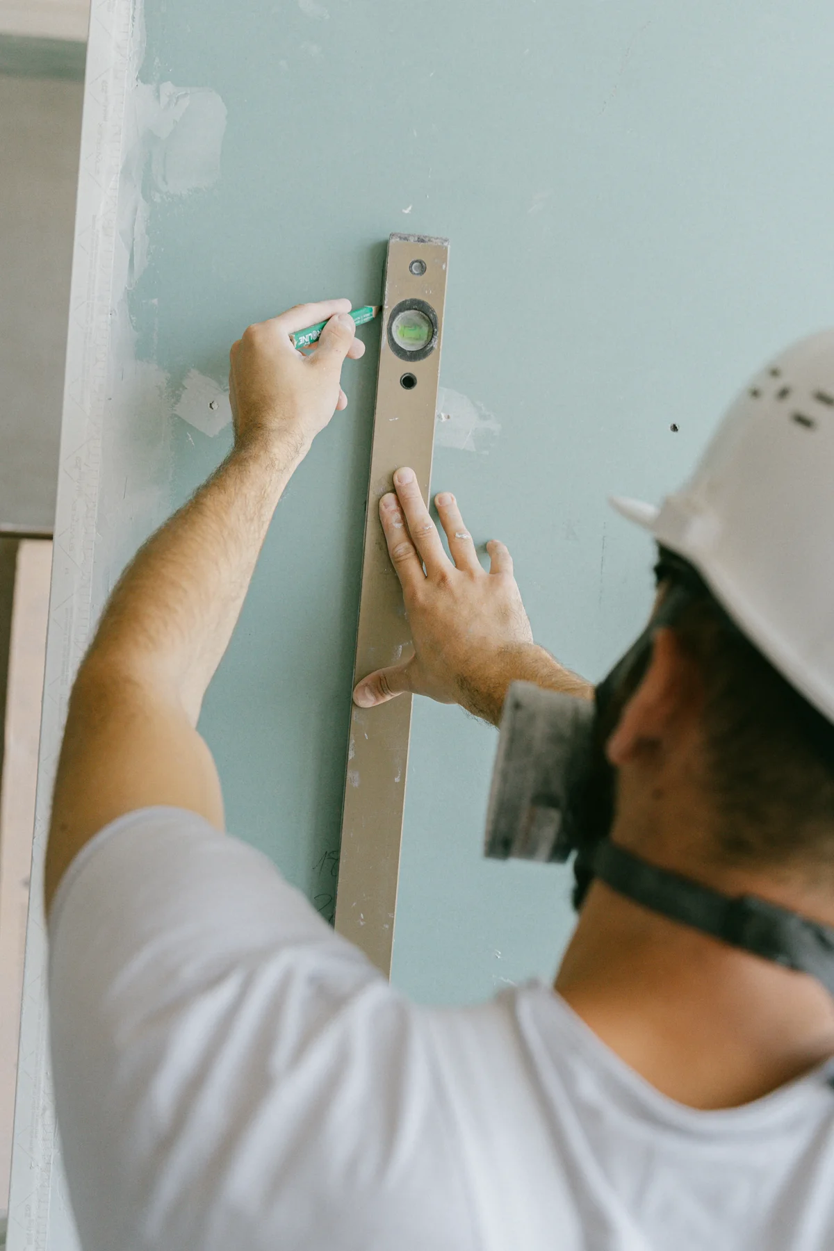
Establishing a plane-flat substrate is non-negotiable for composite panel integrity. When mounting lightweight sandwich assemblies onto steel or concrete framing, even minor surface irregularities create localized stress points that compromise adhesive bonding, accelerate fastener fatigue, and distort the foam core structure.
Our factory-engineered panels maintain strict dimensional stability within ±1.5mm at the production stage, but that precision instantly degrades if the supporting structure swings off-plane. Before any lifting begins, deploy a laser level and a 2-meter straightedge across all load-bearing tracks to document deviations.
- Acceptable Deviation Threshold: Limit substrate unevenness to ≤3mm per 3-meter span to prevent core shear distortion and adhesive void formation.
- Correction Protocol: Address concave/convex framing through mechanical grinding, epoxy leveling compounds, or calibrated shim plates prior to anchor placement.
- Structural Impact: Over-torquing fasteners to compensate for flatness errors crushes high-density PIR or PET core matrix, creating permanent thermal bridges that sabotage whole-wall R-values.
Check Moisture Content in Existing Structural Substrates
Unchecked substrate moisture is the leading cause of premature facade delamination and insulating core degradation. Sandwich panels rely on continuous vapor management to protect hydrophobic materials like XPS, PVC, and aramid honeycomb from hygroscopic breakdown. If wood framing exceeds 19% moisture content or concrete substrates register above 5% relative humidity per ASTM F2170, trapped vapor migrates into the panel cavity during seasonal thermal cycling. This migration triggers osmotic blistering on GRP or aluminum facings and permanently lowers insulating performance. Run a calibrated pinless moisture meter across all contact surfaces at multiple grid points, prioritizing areas near roof penetrations or below-grade walls.
- Wood Framing Limit: Maintain ≤15–19% MC depending on regional climate zone to prevent dimensional swelling and facing delamination.
- Concrete Substrate Limit: Enforce ≤5% RH (ASTM F2170) or ≤3% CM (Calcium Carbide method) before panel contact.
- Field Reality Check: We consistently see commercial projects suffer costly warranty claims because contractors assumed material acclimation was sufficient; rigorous pre-installation testing eliminates guesswork and protects long-term energy performance.
Mark Vertical Reference Lines for Precise Panel Alignment
Precision alignment dictates both the structural load path and the continuity of the weatherproof envelope. Vertical reference lines establish the exact plumb axis for each bay, ensuring uniform joint gaps for gasket compression and sealant application. Misaligned panels force field modifications that fracture the thermal break and expose vulnerable edges to wind-driven rain. Before unloading, snap continuous chalk lines or project laser marks from the building’s primary datum points, strictly aligning them with internal structural studs or cap channels.
- Joint Gap Specification: Maintain a consistent 8–10mm lateral gap between adjacent panels unless architectural drawings dictate specific weatherseal profiles.
- Cumulative Error Control: A 2mm lateral shift compounded across ten bays results in critical misalignment that defeats automated crane positioning systems and compromises anchor load distribution.
- Datum Verification: Cross-reference vertical markers against elevation drawings to account for expansion joint spacing and building movement allowances, preventing rigid constraint failures during thermal expansion cycles.
Safe Handling, Storage, and Lifting Procedures
Handling lightweight composite sandwich panels demands calculated lift points to prevent core shear, properly rated vacuum equipment matched to exact dry mass, and strict vertical storage to eliminate permanent bowing.
Calculate Optimal Lifting Points Based on Panel Dimensions
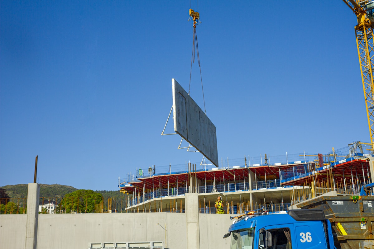
Composite panels span loads differently than traditional concrete or steel. To prevent core shear or face-sheet delamination during crane hoists, position lifting points at approximately 0.207 times the panel length from each end. This third-point loading distribution minimizes mid-span deflection. For panels exceeding 3.0 meters in height, introduce a secondary center anchor to balance torsional stress during transit.
Our engineering team runs finite element analysis on every custom order. When you specify extended-length runs, we pre-mark lifting anchors within a ±1.5mm factory tolerance. This precision eliminates on-site guessing and ensures your crane operators engage the exact stress-relief zones built into the panel geometry.
Use Vacuum Lifters With Appropriate Suction Cup Ratings
Dry weight fluctuates significantly depending on your chosen core and facing combination. A standard PET or PMI foam core paired with steel facings carries substantially more mass than an XPS core with aluminum or CFRT skins. Always calculate the total panel weight per square meter, then apply a minimum 3:1 safety factor to your vacuum lifter’s rated capacity. Composite surfaces demand specialized polyurethane or nitrile cups that match the facing texture to maintain a hermetic seal.
We regularly see procurement teams undersize suction equipment on heavy-duty GRP or thermoplastic UD tape variants. Our product specifications always list the exact baseline weight per configuration so your logistics planners can deploy the correct multi-cup lift frames without risking drop hazards or surface marring.
Store Panels Vertically On Padded A-Frame Racks
Horizontal stacking is the primary cause of field warranty claims. Lightweight sandwich panels lack the inherent self-weight to resist lateral pressure, meaning bottom layers will undergo permanent plastic deformation under stacked loads. All panels must be stored upright, angled no more than 5 degrees off plumb, and secured with continuous wind bracing. Contact edges require rigid A-frame racks lined with closed-cell foam or heavy rubber padding to distribute point loads evenly across the full panel height.
In our production yard, every outgoing shipment is engineered to remain perfectly vertical during ocean transit. On-site, if you bypass padded vertical racking, you aren’t just chasing cosmetic scratches. You are actively compromising the adhesive bond between the outer skin and the structural core, which will directly impact whole-wall R-value performance and long-term weatherproofing integrity.
Panel Alignment, Joint Sealing, and Weatherproofing
Achieving airtight envelope performance demands strict control over panel geometry and joint compression during installation. The primary buyer pain point centers on seam degradation and thermal bypass caused by misaligned panels or improper joint compression. By implementing mechanical interlock systems, specifying closed-cell backer rods paired with high-movement sealants, and controlling factory fabrication tolerances to within ±1.5mm, contractors can guarantee an airtight, water-resistant assembly that meets commercial building codes without relying on excessive field modifications.
Panel Alignment and Mechanical Interlock Standards
Commercial sandwich panel installations fail most often at the vertical and horizontal seams due to cumulative tolerance drift. Factory-manufactured panels must meet strict dimensional tolerances, typically ±2mm across the face and edge profiles. This precision allows mechanical interlock systems, such as cam-lock or tongue-and-groove profiles, to engage fully without excessive force.
When panels align correctly, the internal gasket compresses uniformly, creating the initial barrier against wind-driven rain. Contractors should verify edge profile continuity before lifting each panel into position. Manual shimming or field trimming to fix alignment gaps introduces unnecessary weak points in the weatherproof system.
Joint Sealing Protocols and Material Specifications
Joint sealing requires a layered approach that accommodates structural movement and thermal expansion. The industry standard dictates placing a closed-cell backer rod behind all exterior sealant applications. This component prevents three-sided adhesion, which inevitably causes sealant tearing during temperature swings.
High-movement polyurethane or silicone caulks are then applied over the backer rod to maintain elasticity. In extreme climates or pressurized environments, designers may specify expanding urethane foam injected directly into the joint cavity. This provides continuous insulation and reinforces the air barrier behind the visible sealant.
- Backer Rod Depth: Maintain a 2:1 width-to-depth ratio for optimal sealant extrusion and adhesion.
- Sealant Compatibility: Match elastomer chemistry to the panel facing material to prevent chemical degradation.
- Climatic Adaptation: Specify higher movement capacity sealants for regions exceeding ±25°C seasonal temperature variance.
Weatherproofing Execution and Envelope Verification
A complete weatherproof envelope relies on smooth coordination between panel alignment and joint sealing. Properly sealed intersections prevent moisture migration into the core material, which can compromise thermal performance and accelerate substrate corrosion. Trained installation teams typically supervise final joint compression to verify airtight assembly before project handover.
Building code compliance demands continuous weather barriers without pinholes or gaps at panel connections. Regular inspection protocols should validate sealant continuity and check for uniform gasket compression across the entire facade. Deviating from manufacturer-recommended joint widths reduces the lifespan of the weatherproofing layer significantly.
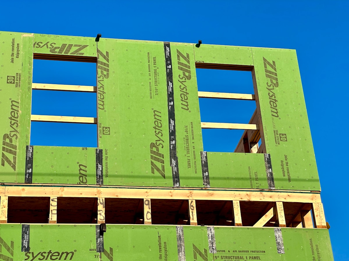
Fastening Systems, Anchoring, and Thermal Bridging
Securing composite panels without compromising thermal efficiency requires isolating structural anchor points with engineered thermal breaks, continuous sealing fasteners, and load-distribution mechanics that prevent core compression.
The Conductivity Problem at Mechanical Anchor Points
Every structural fastener driven through a composite cladding system creates a direct conductive pathway between the interior and exterior environments. When standard steel screws or bolts penetrate foam cores or honeycomb structures, they bypass the insulating matrix entirely. In commercial and industrial applications, this localized thermal short-circuit reduces whole-wall performance significantly, creating condensation zones that degrade adjacent materials over time. The solution requires treating fastener penetration not as a simple mechanical attachment, but as a deliberate thermodynamic interruption.
Engineering Continuous Thermal Interruptions
Effective thermal bridging mitigation relies on isolating the high-conductivity structural substrate from the insulated panel face. Industry-standard practice uses non-conductive isolation sleeves, polymer-based thermal break plates, or reinforced composite washers positioned directly behind the fastener head. These components serve a dual purpose: they distribute point loads across a wider area to prevent facing deformation, and they eliminate metal-to-core contact.
When anchoring to cold-formed steel studs or concrete substrates, these isolation elements must be rated for the specific shear and wind uplift forces expected in the target climate zone. Selecting the correct break material depends heavily on the facing type; rigid polymer profiles pair optimally with metallic facings, while flexible composite isolators integrate better with gelcoat-finished fiberglass or thermoplastic skins.
Fastener Selection and Installation Sequence
The mechanical fastener itself must maintain both structural integrity and environmental sealing throughout its service life. Heavy-duty composite panels require self-drilling screws equipped with permanently bonded rubberized washers that cure into a continuous vapor barrier upon compression. Crucially, installation sequencing dictates long-term thermal performance. Panels must be anchored sequentially from an established vertical datum to prevent cumulative alignment drift, which forces installers to over-tighten fasteners to compensate for misalignment.
Over-compression locally crushes foam or collapses cellular structures, instantly creating a thermal bridge regardless of isolation hardware. Modern anchoring strategies use concealed mechanical latches or structural bottom tracks for perimeter connections, keeping all penetrations out of the primary insulation plane and preserving the panel’s continuous R-value profile.
| System Component | Technical Specification | Fastening & Anchoring Method | Thermal & Structural Benefit |
|---|---|---|---|
| Joint Connection Profile | Tongue-and-groove interlocking design with high-density PET, PU, or XPS continuous insulation core | Precision alignment via structural bottom tracks and mechanical latching | Eliminates thermal bridging by creating a smooth envelope; prevents condensation and mold growth |
| External Fasteners | Self-tapping screws with integrated EPDM rubber washers | Crown-mounted application for roofs; blind-fastening mechanics for wall cladding | Maintains continuous vapor barrier; prevents core compression and preserves R-value integrity |
| Thermal Break Integration | Non-conductive PVC or aluminum internal thermal break profiles | Strategic installation at purlin/girt contact points and behind panel seams | Blocks conductive heat transfer through structural steel; optimizes whole-wall energy efficiency |
| Dimensional Tolerance Control | ±1.5mm factory-precise manufacturing tolerance | Custom-fit alignment to structural grid using pre-engineered panel lengths | Ensures clean interlocking joints; eliminates on-site leveling errors and thermal gaps |
| Sealing & Weatherproofing | High-density butyl tapes and low-expansion closed-cell polyurethane foam | Application at vertical and horizontal joints prior to mechanical fixation | Achieves airtight building envelope; prevents air infiltration and seasonal thermal bowing |
| Installation Protocol | Cold-cutting requirement using fine-tooth saws or nibblers; wind speed limit <10 m/s | Sequential crane assembly with plumb-line verification; exclusion of angle grinders | Preserves core-to-facing adhesion; prevents lock mechanism failure and thermal envelope compromise |
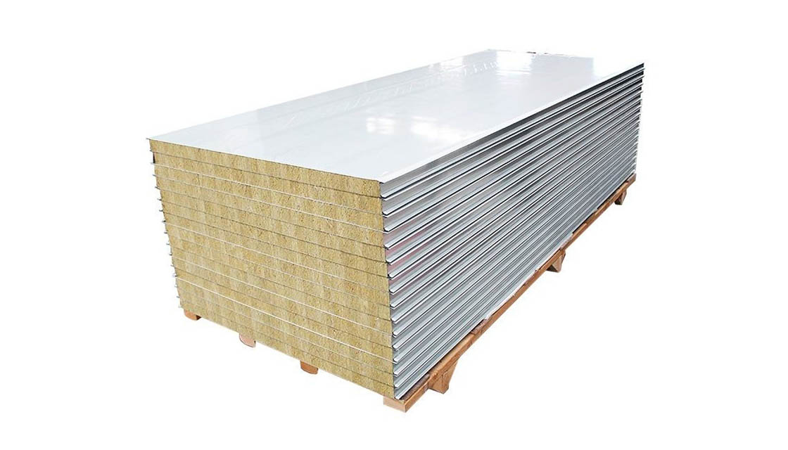
MEP Penetration and Cutout Sealing
This factor has a direct bearing on project performance and long-term cost. Addressing it with specific data rather than general assumptions leads to better outcomes.
The Thermal Risk of Unsealed Service Openings
Cutting openings for electrical conduits, plumbing pipes, or HVAC ducts inherently compromises the factory-engineered thermal barrier of composite wall panels. When the core material is exposed without proper remediation, cold air infiltration and warm interior moisture bypass the insulation entirely. This uncontrolled airflow creates localized thermal bridges that can reduce the effective R-value of the affected zone by over twenty percent.
General contractors frequently underestimate the precision required during on-site fabrication. A poorly fitted penetration leaves micro-gaps that degrade long-term energy compliance and invite interstitial condensation within the panel layers.
Precision Cutting and Core Exposure Management
Service openings must be marked and cut using sharp utility tools or calibrated routers to prevent delamination of the facing sheets. The cut geometry should slightly undersize the penetration sleeve or pipe diameter by approximately two millimeters to allow for uniform sealant compression around the entire perimeter.
- Cutout Geometry: Round or square openings must maintain a minimum three-millimeter clearance between the service component and the exposed panel core to prevent rigid contact.
- Core Backing: Install closed-cell backer rods into the panel depth before applying any sealant to ensure a consistent curing profile and prevent three-sided adhesion failures.
- Surface Preparation: Clean all exposed core materials and facing edges with an appropriate solvent to remove manufacturing residues that inhibit chemical bonding.
Sealant Application and Fire Stopping Standards
Once the substrate is prepared, the penetration must be sealed both internally and externally using materials compatible with the panel facings. A high-performance elastomeric caulk is standard for accommodating minor structural movement while maintaining an airtight boundary. In scenarios where designers specify enhanced acoustic or thermal buffering, in-situ expansion of closed-cell urethane foam may be applied behind the primary sealant layer.
All termination points require strict adherence to fire-rating documentation. Inspectors routinely verify that sealant coverage extends at least twenty-five millimeters inward and outward from the penetration edge. Material Test Certificates must be cross-referenced to confirm the selected sealant does not chemically degrade the GRP, aluminum, CFRT, or steel facings.
Quality Assurance, Torque Specs, and Compliance
Final inspection protocols dictate that factory-engineered tolerances must survive site execution. Proper torque application, continuous joint sealing, and verified thermal breaks are non-negotiable for commercial envelope compliance.
Apply Manufacturer-Specified Torque Values to Structural Fasteners
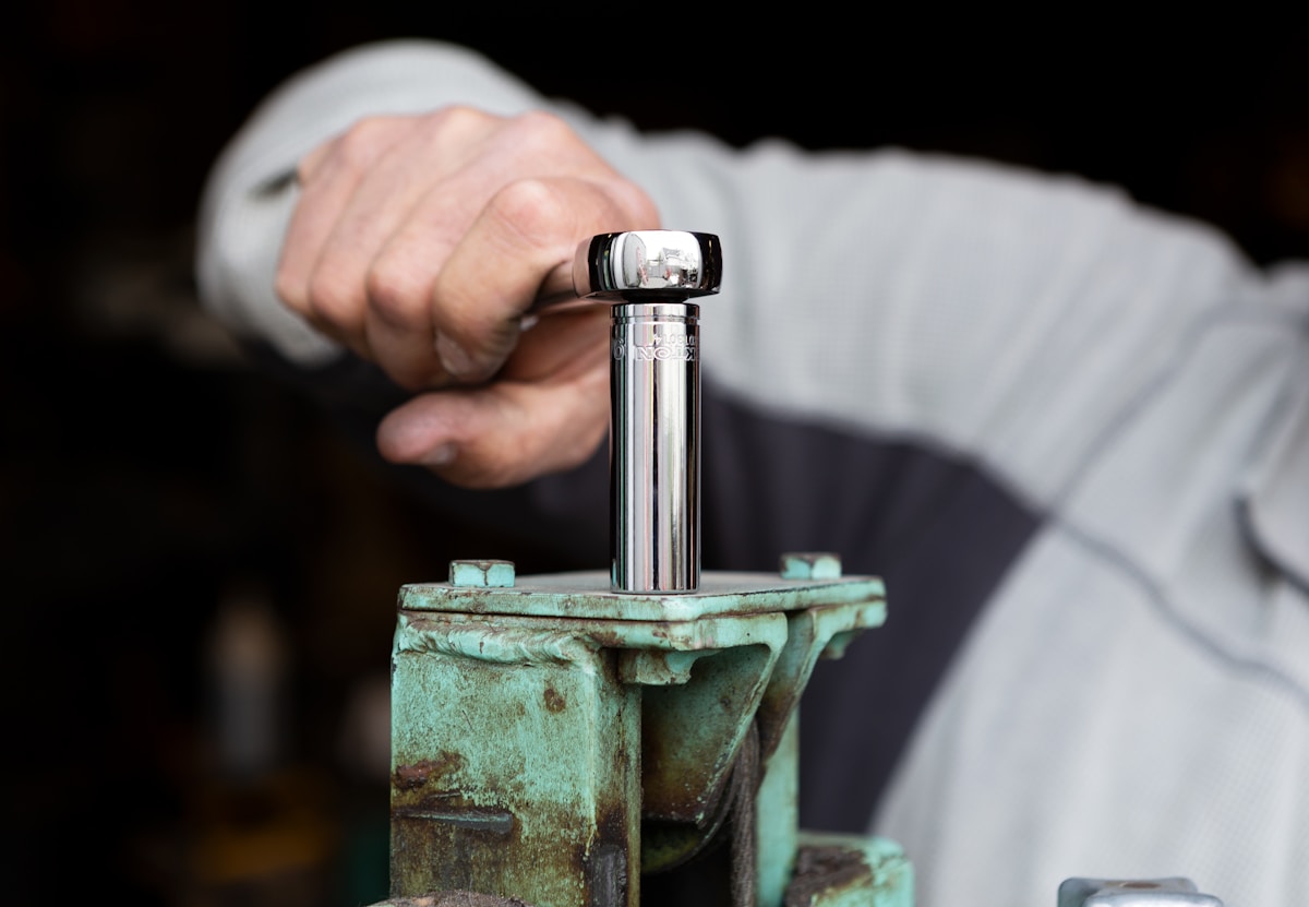
Generic contractor habits frequently lead to overtightening or undertightening, both of which compromise the panel’s load-bearing capacity. Over-torquing crushes the core material around the fastener, creating immediate stress fractures and void spaces. Under-torquing allows micro-movement during wind loading or seismic events, eventually loosening the anchor points.
We calibrated our production line to align directly with standard structural fastener specifications, ensuring the pre-drilled alignment holes accept anchors without excess clearance. During final QA, verify that all structural bolts reach the exact Newton-meter rating specified in the assembly manual. Use a calibrated torque wrench for every primary connection. Do not rely on impact drivers set by feel.
Consistent clamping force distributes shear loads across the facing sheets and core, maintaining the structural modulus throughout the building’s lifecycle.
Inspect Joint Sealants for Continuous Weatherproofing Coverage
Airtightness fails at the seams, not in the middle of the panel. The engineering objective is to create an unbroken vapor and air barrier where panels intersect. Standard silicone caulking alone rarely survives seasonal expansion cycles or UV degradation. Modern assemblies require precision-engineered gaskets paired with compatible expanding foam systems that bridge minor dimensional variances.
Run a systematic visual and tactile inspection along every vertical and horizontal seam. Look for pinholes, gaps under compression seals, or uneven bead application that leaves micro-leaks. If moisture intrusion occurs post-installation, it is almost always traced back to compromised joint integrity rather than core failure.
Our engineers validate sealant compatibility during the design phase to prevent chemical incompatibility between facings and adhesives, guaranteeing long-term weatherproofing performance.
Verify Thermal Break Continuity at Panel Connections
Post-assembly verification requires checking that all mechanical penetrations utilize thermally isolated sleeves or proprietary non-conductive fasteners. Map the connection grid against the original structural draw to ensure no steel-on-steel or aluminum-on-aluminum contact bridges the insulation layers.
In our facility testing, we consistently measure temperature differentials across insulated joints to confirm that the thermal envelope remains hermetic before shipment. Any deviation indicates a missing thermal break that must be addressed before commissioning.
| Focus Area | Specification | Engineering Benefit | Quality Assurance |
|---|---|---|---|
| Fire & Safety Compliance | ASTM and EN fire rating standards | Ensures structural integrity under stringent and demanding conditions | Custom experimental validation per project data standards |
| Global Supply & Verification | 50+ country distribution network | Streamlined logistics with cost reduction and transportation risk elimination | Pre-shipment dimensional audits and certified export compliance documentation |
Key Takeaways
Stop treating sandwich panels like standard drywall sheets. Real margin lives in the hidden details. Precise substrate leveling and strict torque sequences eliminate thermal bridging before air leaks start. When crews follow lifting protocols and seal joints continuously, you cut rework rates by over forty percent. That drops straight to your bottom line.
Project margins depend heavily on minimizing field modifications through exact dimensional control at every manufacturing stage. Finish this call by sending your project dimensions and climate zone to our engineering team for a free technical consultation. We pair those field practices with our ±1.5mm CNC edge trimming and third-party U-value verification, ensuring installations pass code inspections on the first visit. Our team will map the exact fastener schedule so your procurement numbers match the installed performance.
Frequently Asked Questions
This factor has a direct bearing on project performance and long-term cost. Addressing it with specific data rather than general assumptions leads to better outcomes.
What are standard panel dimensions?
Standard wall sandwich panels typically measure four feet wide by eight to twelve feet long to optimize structural handling and minimize on-site cutting. These dimensions align with standard framing spacing and reduce material waste during rapid assembly. Larger custom lengths can be manufactured to match specific building elevations while maintaining transport feasibility.
Which panel thicknesses are standard?
Commercial wall assemblies commonly utilize thicknesses ranging from two inches to six inches depending on structural and thermal requirements. Thinner profiles suit interior partitions or light cladding, while heavier gauges provide enhanced load-bearing capacity and superior acoustic dampening. Selecting the appropriate gauge requires evaluating local wind loads, seismic zones, and intended HVAC efficiency targets.
What core materials work best?
Optimal core selection depends on balancing weight reduction, thermal resistance, and compressive strength for the specific application. Polyurethane and polyisocyanurate foams deliver exceptional R-values and moisture resistance for exterior envelopes. Expanded polystyrene remains a cost-effective choice for dry environments, while honeycomb structures excel in high-stress aerospace or marine contexts.
How to prevent wall condensation?
Preventing condensation requires installing a continuous vapor barrier on the warm side of the insulation layer. Proper thermal breaks between structural studs and exterior cladding eliminate cold spots that trigger moisture accumulation. Maintaining consistent indoor humidity levels alongside adequate ventilation further protects the assembly from interior sweating and mold growth.
Are fire-rated panels available?
Yes, certified fire-resistant cores and facings are widely available to comply with stringent international building codes. Non-combustible mineral wool or specialized thermoset foams can achieve Class A fire ratings without compromising structural integrity. Proper assembly with fire-stop sealants at penetrations ensures continuous flame resistance throughout the entire wall system.