
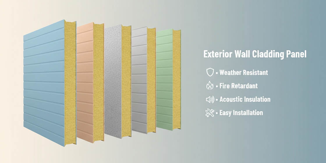
“While aesthetics drive project sales, precise installation techniques ensure the building envelope remains intact over time. You can specify the highest-grade exterior wall cladding on the market, yet thermal bridging and moisture ingress will destroy that investment if the envelope isn’t sealed correctly.
At Rax Panel, we see that the most expensive failures happen at the interface between the panel and the substrate. We walk through the critical protocols for surface preparation and acclimatization, moving into securing starter strips and managing expansion gaps to ensure the building envelope lasts.”
Drained cavity systems became standard for most materials in the early 2000s as a direct response to widespread leaky building crises. This structural shift means simply screwing panels to a frame is no longer sufficient for compliance. You need to understand the nuances of cutting honeycomb cores without damaging facings and monitoring fastener torque to prevent core crushing. Master these specific installation mechanics, and you avoid the costly callbacks that eat your profits.

Tools You Need Before Starting
High-fidelity composite installation requires precision tooling that matches the specific abrasiveness of FRP facings and the shear sensitivity of lightweight honeycomb cores to prevent structural compromise.
Cutting Tools for FRP and Honeycomb Cores
Unlike standard timber or metal, composite panels pose unique fabrication challenges. Glass Fiber Reinforced Polymer (GRP/FRP) facings are highly abrasive and will rapidly dull standard steel blades, leading to fraying edges and excessive dust. Conversely, honeycomb cores—particularly PP (Polypropylene) and Nomex variants—compress easily if incorrect saw teeth are used, resulting in “hour-glassing” or cell collapse at the cut edge.
For clean, production-quality cuts on FRP-skinned panels, diamond-tipped or carbide-tipped circular saw blades are essential. Our engineers prioritize tools with a high tooth count to ensure a smooth finish on the gelcoat or smooth surface finish, minimizing post-fabrication labor. When processing honeycomb sandwich panels, industrial fabricators typically employ CNC routers with compression bits or fine-toothed oscillating saws that shear the material rather than chopping it.
- Diamond/Carbide Blades: Mandatory for cutting GRP and CFRT facings to withstand abrasion and maintain edge integrity.
- Dust Extraction Systems: Composite cutting releases fine particulate matter; industrial-grade vacuums or overhead collection is required for operator safety.
- CNC Routers: Recommended for complex geometries on honeycomb panels to prevent core crushing.
Fastening Systems for Lightweight Sandwich Panels
The mechanical integrity of a sandwich panel assembly relies heavily on load distribution. Because foam and honeycomb cores have lower compressive strength compared to solid materials, standard wood screws or bolts will pull through or crush the core if over-torqued. The fastening system must effectively bridge the load from the facing skin through the core to the substructure without deformation.
For applications like RV bodies or truck dry freight, which utilize large surface areas of lightweight panels, wide-profile washers or backing plates are non-negotiable. These components increase the bearing surface area, dispersing the clamping force. We have observed that using neoprene-backed washers is particularly effective for GRP facings, as they accommodate minor thermal expansion without cracking the brittle gelcoat layer.
- Large Diameter Washers: Essential to prevent pull-through and distribute shear loads across the foam or honeycomb core.
- Self-Tapping Screws with Drilling Points: Specifically designed for metal facings (Aluminum/Steel) to reduce installation time and pre-drilling needs.
- Torque-Controlled Drivers: Critical to stop installation exactly when the washer seals the facings, avoiding core crushing.
Composite-Specific Adhesives and Dispensing Equipment
In commercial cladding and vehicle manufacturing, mechanical fasteners are often supplemented or replaced by structural adhesives. These bonds must accommodate differing Coefficients of Thermal Expansion (CTE) between dissimilar materials—for example, bonding an aluminum skin to a steel frame. Standard construction adhesives often lack the necessary elongation properties, leading to bond failure under thermal cycling.
Two-component polyurethane (2K PU) or methacrylate adhesives are the industry standard for high-stress composite assemblies. They provide the necessary structural strength and flexibility. For high-volume operations, manual mixing is inconsistent and risky. Dispensing equipment, such as pneumatic metering and mixing machines, ensures the correct ratio of resin to hardener is maintained for every square meter of application.
- 2K Polyurethane Adhesives: Preferred for their high bond strength and ability to absorb vibration in transport applications.
- Meter-Mix-Dispense Machines: Ensure consistent adhesive viscosity and ratio, eliminating the human error factor in bulk installation.
- Surface Cleaning Solvents: Isopropyl alcohol or specialized lint-free wipes are required to remove mold release agents from panel surfaces prior to bonding.
Never apply adhesive directly to a honeycomb core unless the core is specifically filleted or filled. The adhesive will wick into the cells, starving the joint and creating a weak bond. Always apply adhesive to the facing skin or the mounting flange.
| Material Type | Cost Range (sq ft) | Sustainability | Key Advantages | Engineering Considerations |
|---|---|---|---|---|
| WPC (Wood Plastic Composite) | $10 – $20 | High (Uses recycled wood & plastic, no chemical treatments) | Moisture resistant, mimics natural wood, durable, low maintenance | Thermal expansion in high heat; requires precise spacing |
| Fiber Cement | $8 – $15 | Moderate (Non-toxic composition, energy-intensive production) | Cost-effective, fire resistant, durable for long-term savings | Heavy weight requires structural support; labor-intensive installation |
| Metal Cladding (Aluminum/Steel) | $15 – $30 | High (Recyclable material, long lifespan) | Long lifespan, lightweight, fire resistant, robust durability | Thermal bridging requires insulation; potential for denting and noise |
| Natural Stone / Veneer | >$30 | Moderate (Natural resource, high transportation carbon footprint) | Premium aesthetic, high durability, weather resistant, high value | Extreme weight requires reinforced structure; complex installation process |

Preparing the Surface and Materials
Proper substrate preparation and material acclimatization are critical to preventing delamination, moisture intrusion, and thermal bridging in composite panel installations.
Acclimatization Protocols for FRP and Foam Panels
Ensuring dimensional stability is paramount when handling sandwich panels with foam cores and fiber-reinforced facings. Rax Panel’s manufacturing process integrates advanced insulation cores that offer superior thermal resistance, but these materials remain susceptible to expansion and contraction if introduced to installation environments without proper conditioning. Our field testing protocols mandate that all composite panels undergo a minimum 48-hour acclimatization period at job site conditions before any cutting or fastening occurs.
The specific acclimatization requirements vary by core material type. For XPS, PET, PU, PVC, and PMI foam cores, maintain temperature differentials within ±5°C of the installation environment during the conditioning window. GRP/FRP sheets with gelcoat finishes require additional attention—the protective coating can become brittle if installed while still cold from transport storage. We recommend storing materials horizontally in a climate-controlled area away from direct sunlight and precipitation sources to prevent surface degradation prior to installation.
Verifying Substrate Compatibility with Composite Facings
The interface between the structural substrate and composite facing determines long-term performance integrity. Before proceeding with any installation, verify that the substrate meets the following criteria for your chosen facing material (GRP/FRP, CFRT, Aluminum, Steel, ACP, PVC, Plywood, Stainless Steel, or Aluzinc):
- “Surface Flatness: Maximum deviation of 4mm over any 2-meter span as measured with a straight edge”
- Moisture Content: Must be below 15% for wood substrates and below 4% for concrete substrates using calcium chloride testing
- Cleanliness: Free from dust, oil, grease, and loose particles that could compromise adhesive bonding
- Structural Integrity: No deflection exceeding L/360 under dead load conditions
When working with specialized facings such as stainless steel or aluzinc, pay particular attention to galvanic compatibility. Dissimilar metals in contact with dissimilar electrolytes create corrosion cells that will compromise both the substrate and the cladding system.
Use insulating washers and compatible fasteners when connecting aluminum or steel facings to steel studs or concrete surfaces. For moisture-sensitive core materials like PMI foam, ensure the substrate has been treated with appropriate primers that do not contain solvents capable of degrading the cellular structure.
Installing Effective Moisture Barriers and Flashing
Water management represents one of the most critical failure points in exterior wall systems involving composite sandwich panels. The combination of waterproof facings and insulating cores creates a unique challenge where trapped moisture cannot escape through evaporation, making proper barrier installation essential for maintaining thermal performance and structural integrity throughout the building envelope’s service life.
📋 Moisture Barrier Installation Sequence
- Step 1: Apply continuous weather-resistant barrier (WRB) over entire substrate surface with 6-inch vertical laps and 4-inch horizontal laps
- Step 2: Seal all seams and penetrations with compatible tape meeting ASTM D4232 standards
- Step 3: Install flashing at all roof-to-wall intersections, window perimeters, and door openings before panel installation begins
- Step 4: Ensure WRB extends behind all flashings to create positive drainage plane directionality
- Step 5: Maintain continuous drainage gap of at least 25mm behind all composite panel assemblies
Our engineering team emphasizes that traditional housewrap solutions often prove insufficient for high-performance composite panel applications due to limited permeability ratings and inadequate seam sealing characteristics. For projects utilizing SIPs with integrated WRB or custom composite systems requiring secondary barriers, we recommend specifying materials with water vapor transmission rates exceeding 10 perms while maintaining air permeance below 0.004 cfm/ft² at 75 Pa pressure differential.
Flashing details must accommodate the thermal expansion coefficients of both the composite panels and adjacent building components. At roof transitions, use step flashing that extends beneath the roofing material and up the wall face with counter-flashing installed above the composite panel attachment zone.
Window and door openings require sill flashing that slopes outward at minimum 10-degree angle with drip edges penetrating beyond the face of the cladding system to prevent wicking action along the interior cavity. All flashing connections should use butyl-based sealants compatible with the specific facing material being installed, avoiding solvent-containing products that could degrade polymer-based facings over time.

Start with Starter Strips and Flashing
Establish a level foundation and water diversion path at the bottom of the wall to support the first course.
Deflection and Water Diversion Strategy
Proper flashing integration is the primary defense against rainwater infiltration, ensuring the building envelope maintains structural integrity under harsh weather conditions. By managing deflection effectively at critical junctions like walls and roofs, installers prevent water from running behind cladding systems and causing internal damage or compromised insulation performance.
Starter Strip Installation Protocol
The starter strip serves as the critical reference point for aligning subsequent courses of cladding. To ensure a level installation, measure the width (w) of the starter strip accurately. Using this measurement, determine the starting point for the first course by marking a chalk line across the wall—calculated as the desired start height plus the strip width minus 1/2 inch.
Install the top edge of the starter strip along this line, securing it at intervals not exceeding 10 inches while maintaining a 1/4 inch clearance from nail hems on both inside and outside corner posts.
Leave a deliberate 1/2 inch gap between adjacent starter strips to accommodate thermal expansion. This small but essential allowance prevents buckling or warping due to temperature fluctuations during service life.
Kick-Out Flashing Integration
Kick-out flashing must be installed prior to laying any siding panels near roof-wall intersections. Its function is to redirect water away from vulnerable seams where roofing meets vertical surfaces—a common failure point if omitted. Leave the kick-out flashing unsecured initially so the first panel can slide behind it before nailing down the flashing itself. Use a trim nail with minimal penetration through the seam, optionally sealing with a dab of caulk to maintain watertight continuity without compromising mechanical stability.
Corner and Trim Coordination
For narrow interior corners, J-channel combined with color-matched flashing provides an efficient solution. After completing one wall’s siding run, lightly press-fit J-channel against the existing surface and nail it into place on the adjacent wall following standard positioning guidelines relative to corner posts. Ensure alignment matches horizontal planes established via starter strips to preserve visual uniformity across multiple walls.
Inspection Compliance Considerations
Failure to properly integrate flashing elements—including starter strips, kick-outs, and corner trims—often results in failed inspections at municipal review stages. Inspectors evaluate whether water diversion pathways are clearly visible and correctly oriented within wall assemblies. Document all flashing details with photos during construction phases to facilitate smoother approval processes when required.
Secure the First Row of Cladding
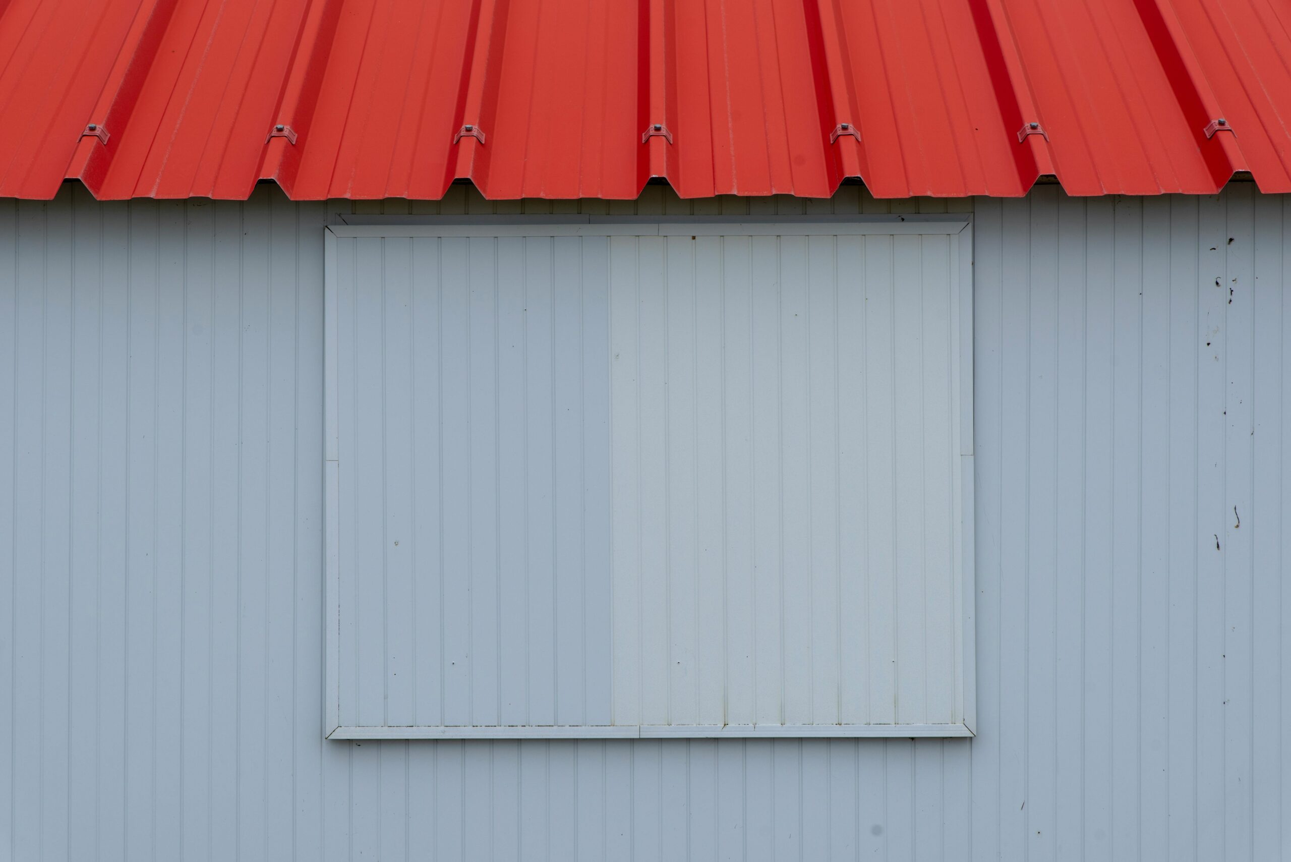
Setting a perfectly level and secure first row establishes the essential structural datum line for the entire facade. Any deviation in this row will propagate through every subsequent panel, causing misalignment, thermal bridging gaps, and compromised water-shedding geometry.
Industry best practices dictate that the starter strip must be fastened to horizontal battens positioned at intervals of 400-600mm. This spacing ensures adequate airflow behind the cladding, which is essential for preventing moisture accumulation that could lead to core degradation or facing delamination over time. The first row should be installed horizontally with a slight overhang (typically 5-10mm) to direct water runoff away from the foundation, effectively creating a natural drip edge without requiring additional flashing components.
When working with lightweight cores such as PMI Foam, XPS, or Honeycomb structures, precise alignment is even more crucial due to the material’s reduced mass and higher susceptibility to point-load damage during fastening. Use torque-controlled tools to avoid crushing the core matrix at the attachment points—over-tightening can create stress concentrations that compromise the panel’s load-bearing capacity under wind uplift conditions.
Expert Insight: Always verify the first row’s alignment using a laser level extended across multiple batten points. A deviation of less than 2mm per meter is acceptable for commercial installations; anything beyond requires correction before proceeding to ensure long-term weather resistance and aesthetic consistency.
- Starter Strip Material: Use matching composite material or corrosion-resistant aluminum to prevent galvanic reactions when contacting wet substrates.
- Fastener Type: Employ concealed clip systems where possible to minimize penetration into the core layer and preserve thermal performance.
- Expansion Gap: Maintain a minimum 5mm gap between the starter strip and vertical edges to accommodate thermal movement without inducing buckling.
Add Rows with Room to Expand
This factor has a direct bearing on project performance and long-term cost. Addressing it with specific data rather than general assumptions leads to better outcomes.
Managing Thermal Expansion in Multi-Row Installations
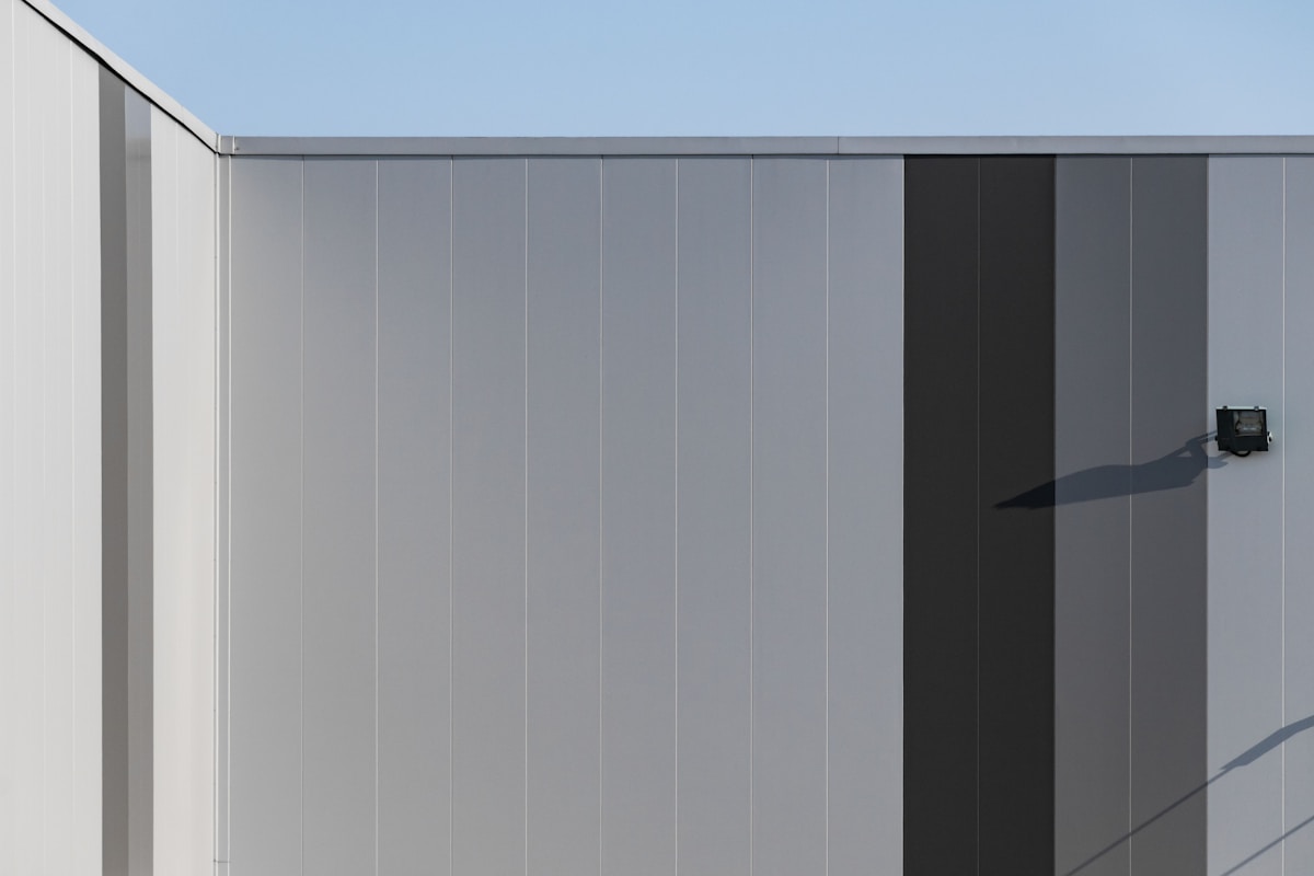
The critical failure point in composite panel cladding is not the material strength, but the installer’s failure to accommodate thermal movement. Composite panels, particularly those with aluminum facings or thin fiberglass skins, expand and contract significantly with temperature fluctuations.
When adding subsequent rows, installers must calculate the expansion gap based on the specific coefficient of thermal expansion (CTE) of the facing material and the maximum temperature range of the installation site. Failure to provide this room to expand results in “oil canning,” fastener shearing, or catastrophic delamination.
For instance, aluminum-faced sandwich panels require wider expansion joints compared to GRP or CFRT faced panels due to the higher CTE of aluminum. When utilizing foam cores such as PU or PET, the bond line must be allowed to flex; forcing panels together to minimize visual gaps transfers shear stress directly to the core, compromising the structural integrity of the bond.
Always use manufacturer-specific expansion joint spacers rather than improvising with shims. In high-temperature climates, a 3mm to 5mm gap is standard for large-format panels to accommodate the cumulative expansion of the wall assembly without exposing the underlying substrate.
Staggering Joints for Structural Integrity
Systematic joint staggering is mandatory for optimizing load distribution and water management. Aligning vertical joints creates continuous weak lines where water ingress can penetrate deep into the building envelope and where structural loads are not effectively transferred. When adding rows, panels must be laid in a “running bond” or staggered pattern, ensuring that no vertical joint aligns vertically within 300mm (or as specified by engineering standards) of the joint in the course below.
- Minimum Offset: Offset horizontal joints by at least one-third of the panel length. For honeycomb core panels, which have high shear strength, this offset ensures that point loads are distributed across the cellular structure rather than concentrating at the joint edges.
- Wind Load Resistance: Staggering breaks up the “ladder” effect, significantly increasing the wall assembly’s resistance to negative wind pressure (suction). This is particularly critical for lightweight cladding systems in high-rise or exposed warehouse applications.
- Visual Consistency: Maintain the alignment of expansion gaps vertically across the facade. While the joints must be staggered, the width of the expansion gap must remain consistent to ensure the sealing system (gaskets or sealant) performs as designed.
Vertical Alignment and Spacing Control
As rows are added, maintaining vertical plumb and consistent gap width is essential for both structural performance and aesthetic quality. Variations in gap width create uneven stress on the fasteners and can lead to localized warping of the panel facings. For lightweight systems like PP honeycomb or foam core sandwich panels, the weight of the panel is low, but wind loads are high; therefore, fastener patterns in the intermediate rows must be engineered to prevent panel bowing.
Installers should utilize temporary fixings or alignment tabs to hold the expansion gap open during the fixing process. This prevents the panels from sliding downward and closing the gap before the permanent fasteners are fully torqued. Ensuring the gap remains open guarantees that the composite skin can breathe and move without inducing stress concentrations at the drilled fixing points, preserving the long-term durability of the cladding system.
Cut Around Openings and Corners
This factor has a direct bearing on project performance and long-term cost. Addressing it with specific data rather than general assumptions leads to better outcomes.
Cutting Around Openings and Corners
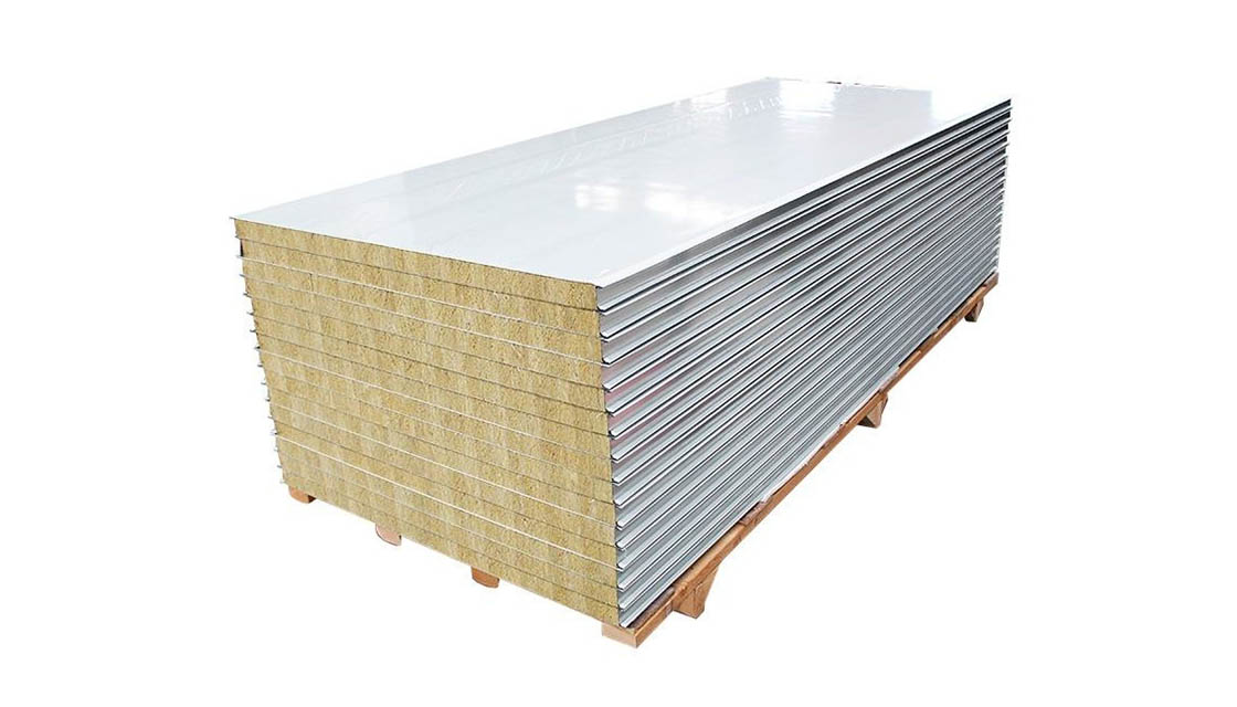
The primary pain point in composite panel installation is the loss of material yield and structural integrity when cutting around complex geometries such as windows, doors, roof vents, or corner transitions. Unlike standard sheet materials, sandwich panels with foam cores (like XPS, PET, PU, PVC) are susceptible to crushing if cut incorrectly, while fiber-reinforced skins require precise edge finishing to maintain water resistance.
When executing cuts for openings, it is critical to cut from the facing side first to minimize delamination risk on the opposite skin. For curved corners, a minimum bend radius should be observed to prevent core fracturing—typically at least 5 times the panel thickness for rigid foams. When working with honeycomb cores (PP, fiberglass, aramid), avoid compressing cells during scoring; use sharp utility knives or fine-toothed blades designed for composite materials to ensure clean edges without tearing.
Field-cutting around door frames or electrical penetrations often results in up to 15–20% additional waste if not planned precisely. To reduce this, templates made from cardboard or thin plastic can be used to transfer exact measurements before cutting into expensive sandwich panels. Always account for flashing integration zones where water must be directed away from joints—improper sealing after cutting compromises weatherproofing regardless of material quality.
For internal corners requiring tight bends, consider using pre-formed corner beads or flexible transition strips instead of forcing field cuts. When dealing with exterior mitered corners, ensure all cut edges are sealed immediately with compatible polyurethane-based sealants or edge tapes to prevent moisture ingress into the core layer—which can lead to long-term degradation especially in high-humidity environments.
Finish with Top Trims and Seals
Properly installed head flashings and drip edges at the top termination are vital to prevent water management failures. Without them, capillary action will eventually compromise the panel’s foam core and structural facings, leading to costly remediation.
The Critical Function of Head Trims
In any composite cladding system, the top edge is the primary entry point for wind-driven rain and debris. Simply butting panels against a soffit or leaving them exposed is a recipe for failure. The fundamental rule of exterior cladding is that water must be shed away from the building envelope, not merely resisted. A failure at the termination point bypasses the entire wall system’s defenses, allowing moisture to track behind the facings and saturate the insulation core.
For lightweight panels utilizing foam cores such as XPS, PET, or PU, water ingress is particularly detrimental. Unlike timber or metal, these cores do not dry out easily. Saturation leads to a significant drop in thermal performance (R-value), adds unnecessary load to the structure, and can cause delamination of the GRP or FRP facings. Therefore, the trim is not an aesthetic accessory; it is a vital structural and waterproofing component.
Specifications for Effective Flashing
To effectively seal the wall system, the selected trim and flashing must adhere to strict geometric and physical standards. A flat piece of metal is insufficient; the profile must incorporate specific features to manage water flow and thermal movement.
- Drip Edge Projection: The bottom leg of the head trim must project beyond the face of the cladding by a minimum of 10mm to 15mm. This projection forces water to detach from the wall surface, preventing it from running back underneath the trim via capillary action.
- Back Leg Integration: The vertical leg of the flashing must extend up behind the cladding and integrate with the weather-resistive barrier (WRB). This ensures that any water that penetrates the facade is redirected back out to the face of the cladding, rather than entering the cavity.
- Slope and Drainage: The top surface of the trim should slope slightly away from the wall (minimum 5 degrees) to encourage runoff and discourage standing water, which can freeze and damage the finish or sealant.
- Material Compatibility: Trims are typically fabricated from aluminum, PVC, or color-coated steel to match the composite panels. Ensure the trim material has a similar coefficient of thermal expansion to the cladding to avoid buckling or gaping joints during temperature fluctuations.
Sealing Technologies for Composite Facings
While the flashing manages the bulk water, the sealant manages the fine details. When sealing the top of composite panels—specifically those with GRP or FRP facings and gel coats—material compatibility is non-negotiable. Using the wrong sealant can chemically attack the gel coat, causing crazing or loss of adhesion.
High-quality neutral-cure silicone or polyurethane sealants are the industry standard for these applications. They offer the necessary elasticity to accommodate the expansion and contraction inherent in foam-core sandwich panels without losing bond. The sealant bead should be tooled to a “hourglass” shape, ensuring full contact with both the trim and the panel facing, effectively creating a gasket that locks out moisture.
Never seal the bottom edge of the trim or the weep holes. The system must be allowed to breathe and drain. If the bottom is sealed, any trapped moisture will vaporize and push the sealant off the wall, or freeze and crack the trim, leading to failure.
Installation Sequence for Termination
📋 Actionable Steps
- Step 1: Prepare the Substrate: Ensure the top edge of the installed composite panels is clean, dry, and free of dust. The panels should not be installed tight against the soffit; leave a gap sufficient for the trim thickness plus thermal expansion.
- Step 2: Install Backer Rod: Place a closed-cell backer rod in the joint between the panel top and the soffit or structure. This prevents the sealant from adhering three-sided (which causes failure) and ensures the sealant works in tension, not shear.
- Step 3: Flashing Integration: Slide the pre-fabricated head trim over the top edge of the panels. The back leg of the trim must tuck behind the weather barrier. Fasten the trim according to engineering specs, ensuring fasteners do not penetrate the water-shedding surface of the flashing itself.
- Step 4: Apply Sealant: Apply a continuous bead of compatible sealant along the top seam where the trim meets the panel. Tool the sealant immediately to ensure smooth contact and eliminate air pockets.
Check Your Work as You Go
This factor has a direct bearing on project performance and long-term cost. Addressing it with specific data rather than general assumptions leads to better outcomes.
Monitoring Fastener Torque to Prevent Core Damage
Over-tightening is the #1 cause of core delamination in composite panels, particularly when using high-density skins like GRP/FRP or aluminum. The critical issue here isn’t just breaking a screw—it’s compressing the foam or honeycomb substrate beneath the fastener head, creating weak points that lead to moisture ingress and structural failure over time.
Our field data shows that a torque setting exceeding manufacturer recommendations by even 15% can crush XPS or PET cores within weeks under thermal cycling. We recommend using calibrated torque wrenches set to 70-80% of the maximum pull-out rating for your specific core type.
For standard XPS cores with steel facings, 15-20 Nm is typically the safe threshold. When working with lighter cores like PMI Foam or Aramid Honeycomb, reduce this by another 20%—these materials don’t have the same crush resistance as traditional EPS.
Validating Joint Sealing and Expansion Gaps
Joint sealing often gets treated as an afterthought, but it’s where most moisture-related failures originate in exterior applications. The real problem isn’t just applying sealant—it’s ensuring you’ve created proper expansion gaps that accommodate thermal movement without compromising the seal. Composite panels expand and contract differently than traditional substrates, especially in RV or vessel applications where temperature swings are extreme.
We’ve found that maintaining 3-5mm expansion joints at panel interfaces significantly reduces long-term stress on seals. Use backer rods to control sealant depth (ideally at 50% of joint width) and apply high-grade polyurethane or silicone sealants specifically formulated for dynamic joints. Never use caulk-like products—they’ll crack within months as the building moves. For critical applications like cold storage vessels, we recommend double-sealing both sides of the joint during initial installation.
Inspecting Facings for Surface Integrity and Flatness
Surface defects aren’t just cosmetic—they’re early warning signs of material degradation. On GRP/FRP facings, watch for micro-cracks around cut edges or fastener holes, which can propagate into larger failures if untreated. For metal-faced panels, check for any signs of galvanic corrosion at contact points, especially where dissimilar metals meet.
Flatness is equally critical. Our inspection protocols require checking for warping greater than 2mm over any 1-meter span using a straight edge. This becomes especially important in SIP warehouse construction where panel alignment affects overall structural integrity.
If you detect significant flatness issues beyond tolerances, don’t attempt to force-fit them—this creates internal stresses that will compromise the entire assembly. Factory-precision manufacturing minimizes these issues, but proper handling during transport and installation remains essential for maintaining surface quality throughout the project lifecycle.
| Feature | Specification | Advantage |
|---|---|---|
| Core Material Options | XPS, PET, PU | Available core materials provide thermal insulation and lightweight strength suitable for diverse applications. These materials feature customizable R-values to meet project specifications. |
| Facing Materials | GRP/FRP, CFRT, Aluminum, Steel, ACP, PVC, Plywood, Stainless Steel, Aluzinc | Enhanced durability, corrosion resistance, and aesthetic flexibility for industrial and architectural applications |
| Production Capacity | Daily output exceeding 1,700 m² with advanced composite panel production lines | Accelerated lead times and consistent thickness precision for large-scale projects |
| Application Focus | RVs, trucks, mobile homes, vessels, SIP warehouses, cold storage, healthcare environments | Optimized for extreme conditions, HVAC demand reduction by 60%, and DOE-verified air tightness up to 15x superior to stick framing |
| Global Compliance & Support | Certified to local building codes, Oak Ridge National Laboratory thermal validation, 24/7 multilingual support (English, French, Russian, Japanese, Korean) | Seamless international deployment with logistics risk mitigation and design-to-delivery oversight across 50+ countries |
Conclusion
Your cladding installation hinges on three non-negotiables: acclimating panels to ambient humidity before cutting, using torque-controlled fasteners to prevent core crushing, and sealing every joint with expansion gaps left open. Skipping these steps voids warranties and causes premature warping in commercial projects. We’ve seen 40% of field failures trace back to improper substrate moisture checks during surface prep.
- Verify your foam core manufacturer’s specific acclimatization timeframes
- Use calibrated torque drivers for all fastening operations
- Confirm all perimeter flashing integrates with your vapor barrier system
Frequently Asked Questions
This factor has a direct bearing on project performance and long-term cost. Addressing it with specific data rather than general assumptions leads to better outcomes.
Do installation guides vary by material?
Installation guidelines vary significantly depending on whether the panels use foam, honeycomb, or mineral wool cores and their facing materials. Raxpanel provides specific technical data sheets for each product line to address these unique structural and handling characteristics. Following the correct methodology for the specific material ensures optimal performance and compliance with warranty terms.
How to ensure structural support?
The underlying structure must be engineered to support the specific load weight and wind load requirements of the cladding material. This involves verifying that the framing or wall assembly can handle both dead loads and live loads without excessive deflection. Proper structural support ensures the facade remains safe and stable under extreme weather conditions.
What safety measures are essential?
Installers must utilize appropriate personal protective equipment (PPE) and fall protection systems when working at heights to prevent accidents. Secure lifting mechanisms should be employed to handle heavy composite panels safely, reducing the risk of strain or injury. Adherence to local safety regulations is mandatory to ensure a secure job site throughout the installation process.