
Cutting aluminum composite material (ACM/ACP) with factory precision requires balancing two distinct materials. Operators must manage the shearing mechanics of 0.50 mm architectural aluminum facings alongside thermoplastic or mineral cores. Standard woodworking saw blades with positive hook teeth grab thin aluminum skins aggressively. This violent biting causes edge delamination, burring, and dangerous kickback. Achieving clean cuts demands carbide-tipped blades featuring a Triple-Chip Grind (TCG) profile with a negative 5-degree rake angle. These specialized blades operate at peripheral tip speeds between 40 and 60 m/s. Concurrently, milling precision V-grooves requires leaving exactly 0.3 mm to 0.5 mm of intact core over the face skin. This precise tolerance eliminates tension cracks along fold lines.
Based on our engineering division’s field experience cutting over 250,000 square meters of architectural composite panels, poor tool selection causes severe plastic melting. Incorrect feed rates ruin entire sheets on jobsites. By standardizing on guide-rail track saws and dedicated non-ferrous carbide blades, field crews maintain tolerances within ±0.5 mm. Regular depth audits with digital calipers ensure consistent quality. These simple shop standards protect decorative coil coatings and eliminate core tear-out entirely.
Choosing the Right Cutting Tools for Every Job
Selecting the right cutting method depends entirely on production volume, panel thickness, and edge quality specifications. While a handheld utility knife suffices for thin sign blanks, large-format cassettes demand motorized guide systems or automated CNC tables. For commercial facade fabrication, explore our full manufacturing catalog of architectural aluminum panels.
Four primary tool categories dominate commercial architectural panel processing:
- Track-Guided Plunge Saws: The premier jobsite solution for straight cuts. Paired with extruded aluminum guide tracks and integrated rubber splinter guards, plunge saws deliver dead-straight cuts across 4-meter sheets without surface scuffing.
- Industrial CNC Routers: High-speed 3-axis flatbed routers utilizing vacuum tables and solid carbide upcut bits. Indispensable for complex curves, window cutouts, fastener perforations, and high-volume batch processing.
- Stationary Table Saws: Ideal for rapid rip-cutting in shop environments. Must be equipped with auxiliary outfeed support tables, zero-clearance throat plates, and continuous downward clamp wheels to prevent panel vibration.
- Heavy-Duty Utility Knives: Fast, silent, and electricity-free for straight cuts on lightweight sheets (≤3.0 mm total thickness with ≤0.21 mm skins). Restricted strictly to interior signage and non-structural soffits.
| Cutting Method | Maximum Thickness | Achievable Tolerance | Edge Quality | Best Production Setting |
|---|---|---|---|---|
| Plunge Track Saw | 6.0 mm Architectural | ±0.5 mm | Clean / Factory-grade | On-site Facade Fitting |
| Flatbed CNC Router | 25.0 mm Solid/Honeycomb | ±0.1 mm | Mirror Polished | High-volume Factory Fab |
| Stationary Table Saw | 6.0 mm Architectural | ±0.8 mm | Minor Burring | Fast Rip-cutting Shop |
| Score and Snap Knife | 3.0 mm Sign-grade | ±1.5 mm | Rough Core Tear | Signage & Display Only |
Why Negative Rake Saw Blades Prevent Edge Grabbing
Standard circular saw blades designed for hardwood feature positive hook angles between +10° and +15°. When a positive-rake tooth bites into thin 0.5 mm aluminum sheet, it acts like an aggressive chisel. This tooth geometry lifts the sheet upward off the guide track, ripping the metal away from the core.
Non-ferrous metal cutting requires a negative rake tooth angle of -5° combined with a Triple-Chip Grind (TCG) configuration. In a TCG blade, a higher trapezoidal tooth cuts a center groove. A lower flat tooth follows immediately behind to clean the corners cleanly. This geometry distributes cutting friction evenly across both metal skins.
The negative angle creates a controlled shearing action. It presses the aluminum sheet downward against the worktable rather than lifting it. For a standard 160 mm track-saw blade, specify 48 to 56 carbide teeth. For a 250 mm table saw blade, specify 72 to 80 teeth. Maintaining this tooth density guarantees that at least two teeth engage the 4 mm composite cross-section simultaneously. This continuous contact eliminates blade chatter and rough jagged margins.
Step-by-Step Circular Saw Cutting on Job Sites
Achieving repeatable, factory-quality straight cuts on a jobsite requires a disciplined mechanical workflow. Fabricators should execute the following five-stage sequence:
- Solid Substrate Support: Never span panels across open sawhorses, which induces center sag and binds the blade. Lay a continuous sacrificial 18 mm MDF or rigid polystyrene insulation board directly across a sturdy cutting table to support the entire panel surface.
- Protective Film Inspection: Ensure the factory polyethylene protective film is firmly adhered with no air bubbles. Do not remove this film before cutting; it prevents metal swarf from scratching the decorative coil finish.
- Track Clamping: Align the track-saw guide rail precisely along your cutting mark. Secure both ends using specialized quick-action track clamps inserted into the extrusion underside T-slots.
- Blade Depth Calibration: Set the plunge cutting depth so the saw blade extends exactly 3 mm to 5 mm through the bottom face of the panel into the sacrificial backer board. Over-extending the blade increases tooth friction and causes rough edge tear-out.
- Smooth Continuous Feed: Power the saw to maximum operational speed (typically 3,500 to 4,500 RPM) before entering the material. Push forward at a steady rate of approximately 25 mm per second without hesitation marks.
| Tool & Diameter | Tooth Geometry | Spindle Speed (RPM) | Feed Rate | Cooling Protocol |
|---|---|---|---|---|
| 160 mm Track Saw | TCG Carbide, -5° Rake, 48T | 3,800 – 4,500 RPM | 1.5 – 2.0 m/min | Dry (Fast Extraction) |
| 250 mm Table Saw | TCG Carbide, -5° Rake, 80T | 3,200 – 4,000 RPM | 2.0 – 3.5 m/min | Dry / Air Jet |
| 6 mm CNC Spiral Bit | Single-flute Solid Carbide Upcut | 18,000 – 24,000 RPM | 6.0 – 9.0 m/min | Continuous Air-Mist Jet |
| 90° V-Groove Router Bit | Carbide Flat-tip (1.5mm flat) | 16,000 – 20,000 RPM | 4.0 – 6.0 m/min | Air Blast Evacuation |
CNC Router Tooling Speeds and Feed Rates
Operating an industrial CNC router on composite panels demands calculating exact chip loads to avoid melting mineral or polymer cores. If feed rates are set too slow relative to spindle RPM, cutter teeth rub rather than shear. This rubbing generates severe frictional heat that liquefies polyethylene cores and gums carbide flutes.
For standard panel profiling, single-flute solid carbide upcut spiral end mills deliver superior chip clearance over double-flute alternatives. Single-flute geometry features an open gullet that expels hot aluminum and plastic swarf instantly upward away from the cut path. For fire-rated panels with dense mineral cores, review our engineering specifications on fire-rated aluminum composite panels class A and A2 guide.
Calibrate spindle speeds between 18,000 and 24,000 RPM matched to feed velocities between 6 and 9 meters per minute. This ratio yields an optimal chip load of 0.25 mm to 0.35 mm per tooth. Equipping the router spindle with a continuous pressurized vortex cold-air jet eliminates the need for messy liquid coolants. Clean air keeps panel edges dry and immediately ready for structural bonding.
Measuring V-Groove Depth for Crisp Ninety-Degree Folds
Architectural rainscreen cassettes are created by routing V-grooves into the back face of an ACP sheet and manually folding the perimeter returns. The critical engineering parameter governing fold quality is residual core thickness over the front skin.
When fabricating a standard 90-degree fold, use a 90° V-groove cutter featuring a 1.5 mm to 2.0 mm flat nose rather than a needle point. The flat nose ensures that when the panel is bent, the folding corner maintains a subtle 2.0 mm outer bend radius. This gentle curvature prevents cosmetic micro-cracking across the high-performance paint film. To learn more about coil-coating longevity, consult our detailed analysis on what is PVDF coating on aluminum composite panels.
Fabricators must calibrate the router depth to remove the rear aluminum skin and the vast majority of the core. Leave strictly 0.3 mm to 0.5 mm of intact core adhering to the 0.5 mm front aluminum facing. Quality control operators must audit this residual core dimension across both sheet ends using digital depth calipers or precision feeler gauges. Routing too deep into the front aluminum skin weakens the hinge, causing the return leg to snap off during installation.
Manual Score and Snap for Thin Sheets
When motorized power saws are prohibited by noise ordinances or suspended scaffolding limits equipment, thin composite panels can be cut manually. However, field crews must understand that architectural exterior panels featuring 0.5 mm skins cannot be processed in this manner.
Manual scoring functions strictly on display-grade panels featuring 0.2 mm or 0.3 mm aluminum skins with low-density polyethylene cores. The technician clamps a heavy steel straightedge firmly along the cut line and executes three to five firm passes using a heavy-duty utility knife or specialized scoring blade. These cuts slice completely through the top aluminum skin into the core.
The sheet is then shifted over a sharp workbench edge and snapped downward cleanly along the score line. Finally, the technician slices the bottom skin from behind to complete the separation. This technique requires zero electricity and produces zero airborne chips, making it ideal for quick interior revisions. To understand overall building design benefits, read our guide on key benefits of aluminum composite panels in modern architecture.
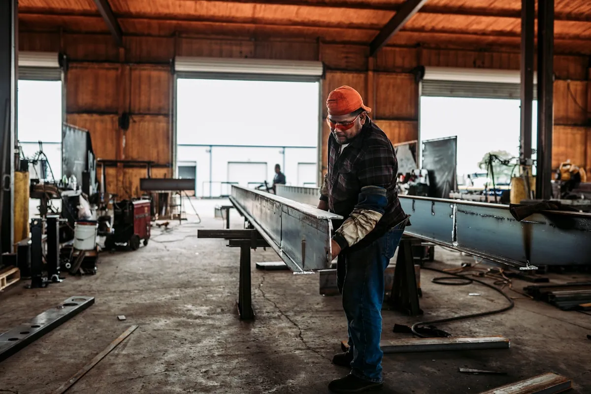
Personal Protective Gear and Dust Extraction Standards
Cutting composite panels generates high-velocity aluminum swarf and airborne polymer particulates that pose severe physical and respiratory hazards. In dry cutting operations, airborne aluminum dust presents a combustible particulate risk governed under OSHA 1910.1200 standards. Industrial workshops must equip cutting stations with Class M or HEPA-filtered dust extraction extractors featuring grounded anti-static vacuum hoses to prevent static discharge sparks.
Field technicians and shop fabricators must wear mandatory personal protective equipment during all saw operations:
- Eye and Face Shielding: High-impact safety goggles certified to ANSI Z87.1 paired with a full-face polycarbonate shield to deflect jagged high-speed metal chips.
- Respiratory Protection: N95 or P100 particulate half-mask respirators to filter out micro-fine mineral fibers and vaporized polyethylene dust.
- Hearing Conservation: Industrial ear defenders providing a minimum Noise Reduction Rating (NRR) of 28 dB against high-frequency circular saw whine.
- Cut-Resistant Gloves: ANSI Level A4 cut-resistant handling gloves to protect hands from freshly sheared razor-sharp aluminum margins during material handling.
Deburring and Edge Finishing for Clean Installations
Regardless of whether cuts are executed via track saw or CNC router, microscopic razor-sharp aluminum burrs inevitably form along cut edges. Leaving burrs intact presents serious laceration risks to installers. Burrs also prevent cassettes from seating flush against subframe aluminum extrusions.
Edge finishing should be integrated immediately after cutting:
- Rotary Deburring Blades: Handheld curved swivel-blade deburring tools (such as Noga tools) clean cut aluminum rims in a single continuous pulling sweep, safely shearing swarf without touching painted faces.
- Fine Mill Files: Single-cut flat bastard files held at a 45-degree angle quickly break outer corners, creating a smooth edge that accommodates wet silicone gaskets.
- Compressed Air Swarf Removal: Blow away all metal dust immediately. Fine aluminum filings trapped between stacked panels act like sandpaper, severely abrading decorative face coatings during transit.
Precision Fabricated Aluminum Composite Panels
Factory-machined ACP cassettes, CNC V-grooving, and custom cut-to-size cladding engineered to AAMA 2605 specifications.
4 Costly Cutting Mistakes That Ruin Panels
To prevent expensive material scrappage and structural failures on facade envelopes, fabricators must eliminate four recurring cutting mistakes:
Using Positive Rake Woodworking Blades on Metal Panels
Mounting standard carpenter blades with positive hook teeth causes severe violent snagging. Teeth dig into the aluminum face and rip sheets away from guide rails. This violent grabbing induces dangerous machine kickback. Fabricators must always specify negative 5-degree TCG blades for non-ferrous alloys.
Cutting Too Deeply When Milling V-Groove Returns
Routing completely through the core scores the interior face of the front aluminum skin. This score line destroys mechanical fatigue resistance during seasonal temperature swings. Over-grooved corners crack easily along the bend line. In heavy winds, weakened cassette returns can snap off the facade entirely.
Pushing Blades Too Slowly and Melting Core Plastics
Advancing saw blades too slowly causes intense frictional heat concentration inside the cut kerf. The thermoplastic core liquefies and sticks tenaciously to spinning carbide teeth. This plastic buildup creates thick melted burrs along panel margins. Operators should maintain a steady forward feed rate between 1.5 and 2.0 meters per minute.
Skipping Spoil Boards During CNC Router Operations
Placing panels directly onto damaged or uneven CNC vacuum beds leads to vacuum pressure leakage. Without uniform suction hold-down, thin composite sheets vibrate violently during cutting passes. This vibration ruins edge squareness and dulls expensive tooling. Always mount fresh 18 mm surfaced MDF spoil boards with flat vacuum channeling.
Frequently Asked Questions About Cutting Composite Panels
What is the best blade type for cutting aluminum composite panels?
Carbide-tipped Triple-Chip Grind (TCG) blades with a negative 5-degree rake angle deliver clean, burr-free cuts without grabbing thin aluminum skins.
Can you cut architectural aluminum composite panels with a utility knife?
No. Utility knife scoring works only on lightweight display panels (≤3 mm with ≤0.2 mm skins). Architectural panels (4 mm with 0.5 mm skins) require circular saws.
How deep should a V-groove be for 90-degree folding?
Leave exactly 0.3 mm to 0.5 mm of intact core material over the front 0.5 mm aluminum skin to create a flexible hinge that prevents fold cracking.
What spindle speed and feed rate should be used on CNC routers?
Operate single-flute solid carbide upcut bits at 18,000 to 24,000 RPM with feed rates between 6 and 9 meters per minute to prevent core melting.
Should the protective film be peeled off before cutting panels?
Keep the protective film on during all cutting and routing operations. It prevents sharp aluminum swarf and saw baseplates from scratching the decorative coil finish.