
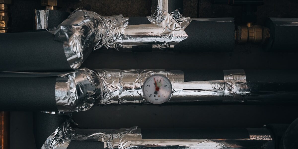
Ignoring a small tear in your insulation jacket today guarantees you will replace a corroded pipe section three years from now. Industrial insulation is your facility’s primary thermal barrier, but once moisture breaches that layer, the hidden damage begins. You are not just paying for wasted energy; you are risking catastrophic failure due to corrosion under insulation.
On cold systems, insulation prevents condensation and corrosion under insulation (CUI), a specific mechanism that shortens equipment life. This guide walks you through how to identify moisture ingress patterns in foam core panels and helps you decide whether to repair or replace compromised systems. At RaxPanel, we focus on material longevity, and following these protocols will help you extend the service life of your infrastructure while keeping maintenance costs predictable.
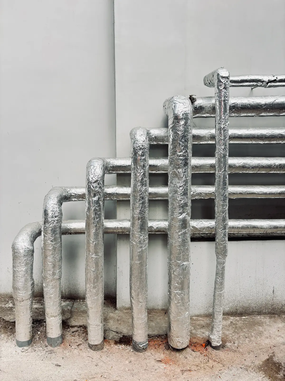
Diagnose Insulation Failures Effectively
Identify Moisture Ingress Patterns in Foam Core Panels
Moisture ingress is one of the most insidious failure modes in sandwich panel systems, particularly in foam-core constructions using XPS, PET, PU, or PVC cores. Closed-cell foams resist initial water absorption, but they are not impervious. When micro-fractures develop in the facing or when sealant joints degrade, liquid water penetrates the core through capillary action along the facing-to-foam interface. In dynamic environments like refrigerated trucks and RVs, vibration and thermal cycling widen these entry points over time. Our field audits consistently show moisture concentrating at the lower third of wall panels, where condensation forms and pools.
The real danger emerges when trapped moisture creates convection loops inside the core. Warm air rises through one path while cooler air descends through another, effectively turning the insulation into a heat exchange medium rather than a thermal barrier. This is why operators often notice increased compressor cycling before any visible surface damage appears. Infrared thermography during a cool-down cycle reveals cold spots that map directly to wet core zones. A simple hammer tap test—listening for a change from a crisp ring to a dull thud—remains the fastest on-site indicator of moisture saturation.
For operators in humid or coastal climates, we recommend specifying PVC or XPS cores over standard PU when prolonged moisture exposure is likely. PET foam cores also demonstrate measurably superior moisture resistance compared to conventional PU formulations, which is why our engineering team frequently specifies them for marine and RV wall applications where both thermal performance and water resistance are non-negotiable.
Detect Thermal Bridge Formation at Panel Joints and Fasteners
Thermal bridges are the silent efficiency killers in insulated panel systems. They form wherever a conductive path bypasses the insulating core—most commonly at panel joints, fastener penetrations, and structural framing intersections. A single metal fastener driven through a sandwich panel creates a direct conductive pathway from exterior to interior, allowing heat to flow freely across what should be a thermal barrier. In refrigerated transport, each unsealed fastener point can increase local heat transfer by 10 to 50 times compared to the surrounding insulated panel area.
The joint types most vulnerable to thermal bridging are end joints where two panels meet edge-to-edge, T-joints where a panel intersects a perpendicular structure, and corner joints where two planes converge. Without proper thermal break gaskets or insulated joinery systems engineered into the design, these joints become the primary leakage paths. We see this repeatedly in field inspections: panels that perform within specification in isolation but fail to meet system-level thermal requirements because the joint design was treated as an afterthought rather than an engineered component.
- Fastener selection: Use thermally broken fasteners with insulating sleeves or washers that minimize conductive contact between the metal fastener and both facing sheets.
- Joint sealing: Apply closed-cell elastomeric sealants at all panel interfaces. Standard acrylic or silicone sealants degrade under UV exposure and thermal cycling, creating new breach points within 2 to 3 years.
- Framing integration: Ensure structural framing members are thermally isolated from the panel interior using insulating pads or gaskets at every contact point.
Assess Core Compression and Density Loss Over Service Life
Foam core materials are not static—they undergo physical changes throughout their service life. The primary mechanism is compression set, where the cellular structure collapses under sustained mechanical load. This is especially critical in floor panels and structural applications where point loads and distributed weights are constant. XPS and PET foam cores generally resist compression better than PU and PVC variants, but even these materials experience gradual density reduction under heavy or dynamic loading.
Density loss directly correlates with thermal performance degradation. The insulating value of a foam core depends on the gas trapped within its closed cells. As the cellular structure compresses, cell walls collapse, insulating gas escapes, and ambient air—which has significantly higher thermal conductivity—replaces it. A core originally rated at 35 kg/m³ may drop to 28 kg/m³ or lower after years of service, and the corresponding decline in thermal resistance is proportionally significant. Our testing protocols include periodic density verification on returned panels, and when we document a density drop exceeding 15% from the original specification, we flag the panel for full thermal re-evaluation.
For high-load floor applications in truck and RV construction, we recommend specifying high-density XPS or PET foam cores rated for the expected load profile. Our engineers design these cores with reinforced cell structures that maintain density integrity under sustained compression, which is why our floor panels for refrigerated trucks consistently pass thermal performance checks even after extended service periods in demanding operations.
Recognize Facing Delamination and Gelcoat Degradation Signs
Delamination—the separation of the facing sheet from the core material—is a progressive failure that begins at the microscopic level and becomes visually apparent only after significant damage has accumulated. The bond between GRP or FRP facings and foam cores is created during manufacturing under controlled temperature and pressure. When this bond is compromised by manufacturing defects, impact damage, or chemical exposure, the facing begins to separate from the core, and the panel’s structural and thermal integrity declines in tandem.
Gelcoat degradation on FRP facings follows a predictable lifecycle. UV exposure initially causes chalkiness—a powdery residue that forms as the resin matrix breaks down. As degradation progresses, micro-cracks appear in the gelcoat layer in a network pattern known as craze cracking. These cracks allow moisture and contaminants to reach the underlying fiberglass matrix, accelerating both structural weakening and core exposure. The most reliable early detection method remains the hammer tap test performed systematically across the panel surface: a consistent ringing sound indicates intact bonding, while a dull flat sound signals delamination.
- Surface chalkiness: Rub the panel surface with your hand. If a white residue transfers to your skin, the gelcoat is degrading and the underlying reinforcement is exposed.
- Craze cracking: Inspect the facing under bright light at a low angle. Network-pattern micro-cracks that were not present at installation indicate UV and thermal fatigue.
- Bulging or waviness: View the panel surface from the side at eye level. Any deviation from flatness suggests core-to-facing separation in that region.
- Fastener pull-through: Check whether fastener heads sit flush or have pulled slightly into the facing. This indicates the facing has lost structural integrity around the penetration point.
When delamination is confirmed, the affected panel section should be replaced rather than repaired. Patch repairs on delaminated sandwich panels rarely restore the original structural and thermal performance. For new constructions where surface durability and moisture resistance are critical, we specify CFRT-facing panels with gelcoat finishes. Our continuous fiberglass reinforced thermoplastic facings demonstrate significantly better adhesion stability to foam cores over extended service life compared to traditional hand-laid GRP alternatives, reducing the likelihood of the delamination cycle described above.
| Failure Symptom | Diagnosis (Root Cause) | Engineering Solution | Material Specs | Result |
|---|---|---|---|---|
| Thermal Efficiency Loss | Convection loops in cellular cores or moisture ingress in dynamic environments like trucks/RVs | CFRT & Foam Core Sandwich Panels | PU, PET, or PVC Foam Cores with Aluminum or GRP facings | Eliminates thermal bleed, reduces compressor cycling, and lowers energy costs |
| Structural & Thermal Trade-off | High-density materials compromising thermal resistance under mechanical stress | GRP Honeycomb & Fiberglass Foam Panels | PP Honeycomb or XPS/PET cores composited with Fiberglass sheets | Optimizes lightweight strength without sacrificing insulation performance |
| Environmental Degradation | Water corrosion, mold growth, or surface fatigue on traditional materials | Gel Coat FRP & Thermoplastic Sheets | Continuous fiberglass reinforced thermoplastic (CFRT) with waterproof gel coat | Superior waterproofing and resilience extending lifecycle and reducing maintenance |
| Fire Safety Compliance | Inability to meet rigorous non-combustibility standards (e.g., EN 13501) during inspections | Mineral Wool Sandwich Panels | Mineral wool sandwich panels designed for exterior wall cladding | Ensures compliance with global safety regulations and mitigates fire risk |
| Lifecycle Cost Overrun | Frequent repairs due to poor fit or material unsuitability for specific conditions | Custom Engineered Manufacturing | Custom-engineered composites with XPS, PET, PIR, or PVC cores and aluminum/fiberglass facings | Precision-tested solutions that ensure durability and reduce total cost of ownership |
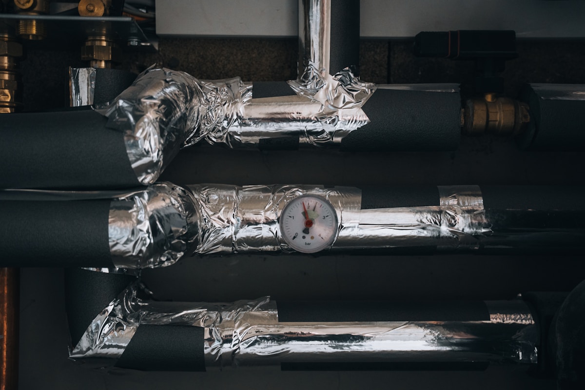
Identify Common Causes of Insulation Damage
Insulation failure is rarely random; it is almost always the result of specific mechanical, chemical, or thermal stressors exceeding the material’s design limits. The three primary root causes are moisture intrusion compromising the core, mechanical loads causing permanent compression, and thermal cycling inducing bond failure.
Moisture Intrusion and Corrosion Under Insulation (CUI)
Moisture is the single most destructive force in industrial insulation systems. When water vapor penetrates the outer facing—whether through microscopic pinholes in gel coats, compromised joints, or damaged sealants—it migrates into the core material. In foam core sandwich panels utilizing XPS, PU, or PET, moisture saturation displaces the insulating gas within the cell structure. This drastically increases thermal conductivity, effectively rendering the insulation useless and adding significant weight to the structure.
More critically, on systems with metal facings or underlying steel infrastructure, trapped moisture creates a perfect environment for Corrosion Under Insulation (CUI). This phenomenon occurs when water is held against the substrate by the insulation layer, preventing evaporation and accelerating oxidation rates. For FRP or GRP sandwich panels, while the facing itself is corrosion-resistant, water ingress can lead to core degradation and the delamination of the bonding laminate if the core material is hygroscopic or if the interface lacks proper waterproofing adhesives.
- Capillary Action: Water can wick through joints and fastener holes if they are not perfectly sealed, bypassing external coatings.
- Vapor Drive: In high-temperature applications, the vapor pressure differential can force moisture deeper into the panel core if the vapor barrier orientation is incorrect.
- Freeze-Thaw Damage: In colder climates, absorbed moisture expands upon freezing, physically rupturing the cell walls of PU or PET foam cores from the inside.
Mechanical Stress and Core Compression
Industrial environments are harsh, and insulation systems frequently face physical abuse that leads to structural damage. The most common mechanical failure is core compression. Every insulation material, from rigid PMI foam to PP honeycomb, has a specific compressive strength threshold. When point loads—such as foot traffic during maintenance, dropped tools, or localized impact from machinery—exceed this threshold, the core cells collapse.
Once a foam core is compressed, it does not rebound. This creates a permanent “thermal bridge” or short circuit in the insulation system. In honeycomb panels, while the structure offers high stiffness-to-weight ratios, localized impact can cause buckling of the cell walls, leading to a faceted dent that compromises the aerodynamic or hydrodynamic properties of the surface and potentially cracks the outer skin.
Over-tightening fasteners is a frequent installation error. Excessive torque can crush the core material around the fastener head, reducing the effective bearing area and creating a direct path for heat transfer or water ingress.
Thermal Degradation and Cycling Fatigue
Insulation materials are often selected based on their continuous service temperature. However, damage often occurs not just from exceeding the maximum temperature, but from the frequency of fluctuation. Thermal cycling causes differential expansion between the skins and the core. For instance, aluminum facings expand at a different rate than FRP or stainless steel facings.
This constant movement stresses the adhesive bond line. Over time, this fatigue leads to debonding or delamination, where the facing separates from the core. Once delamination occurs, the facing loses its structural support and becomes vulnerable to buckling under wind loads or vacuum pressure. Furthermore, chemical exposure can accelerate thermal degradation. Hydrocarbons or specific industrial solvents can dissolve or soften certain thermoplastic cores (like PP or PET) or damage the gel coat layer on FRP sheets, reducing their glass transition temperature (T<sub>g</sub>) and causing softening under operational heat loads.
Material-Specific Failure Susceptibility
Different core compositions utilized in sandwich panels react uniquely to these stressors. Selecting the correct core requires understanding the specific failure mode of the material in the operational environment.
| Core Material | Primary Failure Risk | Resistance to Moisture |
|---|---|---|
| PUR / PIR Foam | Brittle at low temperatures; prone to friability and cracking under impact. | Moderate; open-cell variations absorb water rapidly if facing is breached. |
| XPS Foam | Can soften under high sustained temperatures (>75°C). | High; closed-cell structure offers excellent water absorption resistance. |
| PET Foam | Thermal expansion must be managed; can creep under constant heavy load. | Low to Moderate; generally hydrophobic but cut edges must be sealed. |
| PP Honeycomb | Cell wall buckling under point impact; requires skins for stability. | High; inert to water but requires drainage if facing is compromised. |
How to Inspect for Warning Signs
Early detection of insulation system degradation mitigates corrosion risks and thermal efficiency losses. A rigorous inspection regimen focusing on visual anomalies and thermal differentials is essential for extending the service life of composite panel systems.
Establishing a Structured Inspection Cadence
For industrial facilities utilizing composite sandwich panels or advanced insulation systems, a reactive maintenance approach is often too late to prevent underlying damage. A structured inspection cadence must be implemented based on the operational environment’s severity. In high-humidity or coastal applications where Chloride-induced stress is prevalent, monthly visual inspections are recommended. For standard industrial environments, a quarterly visual check combined with an annual thermographic survey provides a baseline for asset integrity. This frequency ensures that minor jacketing breaches—which serve as entry points for moisture—are identified before they escalate into widespread corrosion under insulation (CUI) or core saturation.
Visual Indicators of Facing and Jacketing Degradation
The external facing or “jacketing” is the primary barrier against environmental elements. Inspectors must systematically evaluate the condition of these materials, whether they are Glass Reinforced Plastic (GRP) with gelcoat finishes, aluminum, or steel. A detailed visual scan should focus on specific failure modes that compromise the system’s weathertightness.
- Gelcoat Micro-fractures: On GRP or FRP facings, look for “crazing” or hairline cracks in the gelcoat surface. These micro-fractures expose the underlying laminate to water ingress, leading to blistering and fiber bloom.
- Mechanical Impacts and Dents: Inspect metal jacketing (Aluminum/Steel) for dents or creases that may have penetrated the vapor barrier. Even small deformations can create “cupping” that holds water against the insulation core.
- Sealant and Gasket Failure: Check laps and joints for cracked, peeling, or missing sealant. UV degradation often hardens butyl tapes or caulks, breaking the seal and allowing moisture to wick into the panel joints.
- Corrosion Staining: Look for rust streaks or discoloration emanating from fasteners or lap seams. This is a definitive indicator that water has breached the outer skin and is reacting with the internal components or the substrate.
Thermal and Moisture Detection Protocols
Visual inspections often miss subsurface damage, particularly within foam cores (XPS, PU, PET) or honeycomb structures where internal delamination does not immediately show on the surface. Technicians should deploy non-destructive testing (NDT) tools to validate the thermal performance of the insulation envelope.
- Infrared Thermography: Use infrared cameras to scan for thermal anomalies. “Hot spots” on cryogenic lines or “cold spots” on hot piping indicate insulation compromise or moisture ingress, as wet insulation has significantly higher thermal conductivity than dry material.
- Capacitance/Impedance Testing: For non-metallic jacketing systems, utilize moisture meters that measure dielectric properties. This allows for quantitative mapping of water accumulation within foam cores without piercing the facing.
- Core Sampling Verification: If non-destructive methods indicate potential saturation, conduct a small core extraction to verify the density and moisture content of the core material (e.g., checking if a PU foam has crumbled or absorbed water).
Structural Integrity Checks at Joints and Fasteners
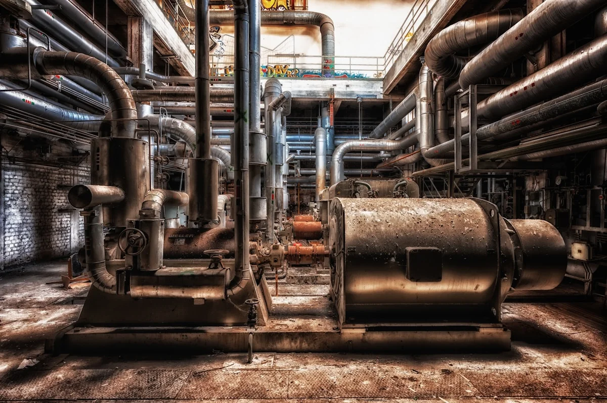
The weakest points in any industrial insulation system are the penetrations and mechanical connections. During the inspection cadence, specific attention must be paid to the hardware securing the jacketing and the seams between panels.
- Fastener Condition: Inspect screws, rivets, and washers for signs of galvanic corrosion, especially where dissimilar metals meet. Missing or popped fasteners create immediate openings for water and pests.
- Joint Alignment: Verify that panel joints remain tight. Gaps wider than 1-2mm suggest underlying thermal expansion issues or structural settling that may have torn the internal vapor barrier.
What External Forces Damage Insulation
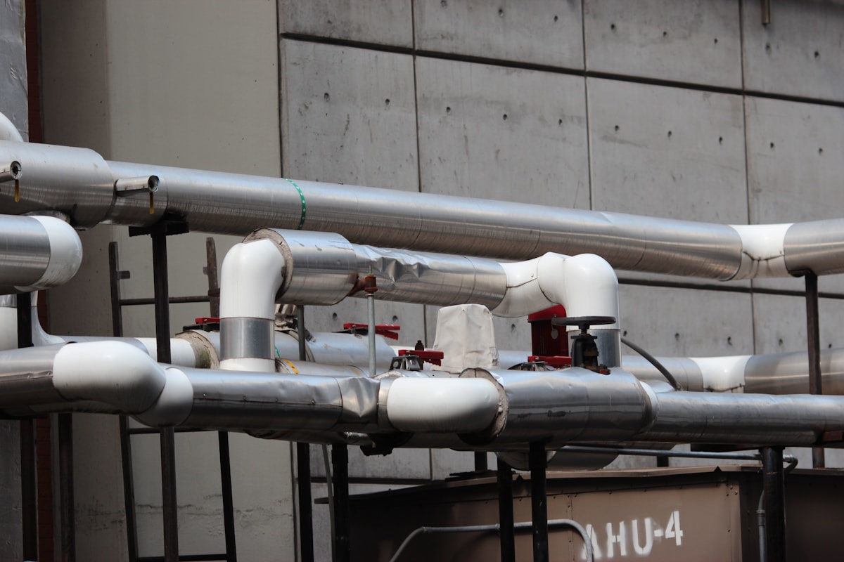
Cumulative damage, not isolated incidents, drives the majority of industrial insulation failures. This reality becomes especially apparent when examining penetrations and mechanical connections, where the integrity of the insulation system is most vulnerable.
Thermal Cycling and Expansion Stress
Differential thermal expansion between facing and core materials is a primary driver of bond degradation. Because the Coefficient of Thermal Expansion (CTE) differs between materials—for example, aluminum skins expand at a different rate than PET foam cores—this differential movement creates internal strain.
Unsealed honeycomb cells introduce a secondary thermal failure mode distinct from adhesive degradation. In PP or fiberglass honeycomb panels, thermal cycling can induce convection loops if the cell walls are not perfectly sealed. Air circulating within the open cells transfers heat much faster than stationary air, effectively nullifying the insulation properties and leading to unexpected thermal bleed.
Moisture Ingress and Corrosion Under Insulation (CUI)
Moisture migration through compromised facings initiates the most costly hidden failure pathway in insulation systems. Once water breaches the outer facing—typically through micro-cracks in gel coats, poorly sealed joints, or fastener holes—it migrates into the core material. While closed-cell foams such as XPS and PU provide significantly higher water resistance than open-cell alternatives, prolonged exposure eventually leads to saturation, degrading the core’s structural and thermal performance.
When insulation becomes wet, its thermal conductivity increases drastically; wet insulation can conduct heat over 20 times more efficiently than dry material. In cold applications, this moisture creates a freeze-thaw cycle that physically ruptures the cell structure of the foam core. Crucially, in metal systems, moisture trapped against the substrate creates a prime environment for Corrosion Under Insulation (CUI), a hidden threat that can catastrophic failure to pipes and vessels before it is visually detected.
Mechanical Vibration and Impact
Industrial environments are rarely static. Equipment vibration, structural movement, and physical impacts during operation or maintenance pose severe risks to insulation integrity. Repeated vibration can cause “fatigue failure” in the bond line, resulting in delamination where the skin separates from the core. This creates air gaps that drastically reduce thermal performance and compromise the structural load-bearing capacity of the panel.
While high-density materials are often chosen for structural integrity, they are not immune to damage. Impact from dropped tools or debris can dent aluminum facings or fracture brittle GRP/FRP skins. Even if the surface appears intact, the underlying foam core—whether PU, PET, or PVC—may suffer compression damage, permanently reducing its thickness and thermal resistance in that specific area. Lightweight solutions like CFRT (Continuous Fiber Reinforced Thermoplastic) offer higher resilience to impact compared to traditional brittle materials, maintaining structural integrity without sacrificing weight.
Chemical Exposure and Ultraviolet Radiation
External environments subject insulation to chemical and solar degradation. Ultraviolet (UV) radiation breaks down the polymer chains in unprotected facings, causing chalking, loss of gloss, and surface embrittlement. While GRP/FRP panels with high-quality gel coats provide a strong barrier against UV, prolonged exposure without maintenance eventually leads to micro-cracking, which then acts as a pathway for water ingress.
Additionally, industrial cleaning agents, acid rain, or airborne pollutants can chemically attack the insulation facings. Certain solvents can degrade the surface of PVC or PU foams, while acidic atmospheres can corrode metal facings like steel or aluminum. Selecting chemically resistant skin materials and protective coatings is essential to prevent the external environment from eating through the defensive layers of the insulation system.
Follow a Preventive Maintenance Schedule
Adhering to a preventive maintenance schedule is the most effective method to mitigate the high costs associated with unplanned downtime. By shifting from reactive repairs to scheduled interventions, facility managers can extend the service life of composite panels by up to 30% while stabilizing operational expenditures.
Establishing Frequency Protocols for Industrial Environments
The frequency of maintenance cycles must be dictated by the operational environment rather than a generic calendar. In controlled environments, semi-annual inspections may suffice. However, in high-risk sectors such as chemical processing or marine applications where CFRT and GRP sandwich panels are exposed to corrosive agents, quarterly visual inspections are mandatory. The objective is to detect degradation in the protective gelcoat or sealant before the core material is compromised.
For facilities utilizing foam core sandwich panels with facings like Aluminum or Steel, the schedule must include thermal scanning. Due to the high thermal conductivity of metal facings, minor delamination or core compression creates immediate thermal bridges. A bi-annual infrared scan can identify these anomalies early, preventing the energy losses that often go unnoticed until they result in significant utility spikes.
Assign specific maintenance protocols based on the core material. PET and PU foam cores possess higher water absorption rates than XPS or PMI. If your facility uses PU-cored panels, prioritize joint seal inspections immediately after any rainfall or washdown cycles to prevent core saturation.
Actionable Maintenance Execution Checklist
Executing a maintenance schedule requires a standardized checklist to ensure consistency across shifts. This approach eliminates human error and ensures that minor issues—such as a loose fastener or a hairline fracture in the gelcoat—are addressed immediately. The “fix-it-now” mentality during routine checks prevents the accumulation of damage that leads to panel replacement.
- Sealant and Joint Integrity: Visually inspect all panel junctions and penetration points. Look for cracks, shrinkage, or adhesion loss in the sealing compound. degraded seals are the primary vector for moisture ingress into foam cores.
- Surface Cleanliness and Coating Assessment: For GRP/FRP panels with gelcoat finishes, check for chalking, fading, or micro-fractures. While gelcoat provides a waterproof barrier, UV exposure degrades its surface integrity over time. Clean surfaces with mild detergents to prevent pollutant buildup that can mask structural cracks.
- Fastener and Mechanical Connection Audit: Verify torque levels on bolts and rivets. Thermal expansion and contraction cycles often loosen fasteners, creating gaps that compromise both structural integrity and thermal insulation performance.
- Impact and Damage Survey: Document any dents or punctures. On honeycomb panels, an impact may not look severe externally but can collapse the internal cell structure, drastically reducing compressive strength.
Documentation and Lifecycle Tracking
A maintenance schedule is only as valuable as the data it generates. Facilities must maintain a log of all inspections, noting the specific location and severity of any defects. This historical data is crucial for predicting the lifespan of the insulation system. For example, if XPS core panels in a specific zone consistently show sealant degradation every 18 months, the schedule can be adjusted to 12 months, proactively managing the risk.
This data-driven approach allows procurement teams to forecast replacement needs accurately. Instead of emergency procurement at premium prices, materials can be sourced during standard purchasing cycles, leveraging bulk pricing and avoiding operational interruptions.
Ignoring “minor” cosmetic damage on sandwich panels is a common error. On metal-faced panels, scratches expose the substrate to corrosion. On FRP panels, gelcoat breaches allow water to wick into the fiberglass laminate. Any breach through the facing layer should be treated immediately as a critical defect.
Learn From Real-World Case Studies
Documented facility outcomes prove that structured inspection and preventive maintenance directly reduce downtime, extend insulation service life, and lower total cost of ownership across industrial applications.
CFRT Sandwich Panels in Refrigerated Transport Fleets
A regional logistics operator deployed CFRT sandwich panels for refrigerated truck body construction across a fleet of 120 units. The selection was driven by the need to reduce vehicle payload weight while maintaining thermal performance over a demanding 8-year operational cycle.
Quarterly thermal imaging inspections were implemented from Year 1. Data tracked panel surface temperatures at junction points and fastener locations. By Year 3, minor sealant degradation was detected at two cargo door interfaces on three units. The proactive replacement of sealant strips prevented moisture ingress into the CFRT facing and core interface.
- Maintained thermal conductivity: Approximately 0.024 W/(m·K) after 5 years of continuous operation, within 4% of initial factory-rated values.
- Unplanned downtime reduction: 18% lower compared to the previous fleet configuration using conventional aluminum composite panels.
- Total cost of ownership over 8 years: Estimated 22% lower, driven by reduced compressor runtime and fewer emergency panel replacements.
Foam Core Panels in Cold Storage Warehouse Operations
A food distribution facility installed polyurethane (PU) foam core sandwich panels for cold storage walls and roofing operating at -25°C. The facility implemented an annual inspection protocol combining thermal imaging surveys and visual assessment of panel joints and fastener points.
In Year 2, thermal imaging revealed a ΔT of 3.2°C at specific panel joints, indicating thermal bridge formation due to fastener compression set. The preventive maintenance team resealed the affected joints and replaced compressed fastener gaskets. Post-intervention re-measurement showed ΔT reduced to 0.8°C.
- Compressor runtime reduction: Approximately 14% annually after corrective resealing, translating to significant energy cost savings.
- Corrosion under insulation (CUI) mitigation: The closed-cell PU foam core inherently resists moisture absorption, eliminating the CUI risk that commonly affects bare steel cladding systems in cold storage environments.
- Insulation lifespan extension: Structured inspections extended the effective service life of the panel system beyond the standard 15-year design expectation.
Honeycomb Core vs. Foam Core in Industrial Equipment Enclosures
An industrial equipment manufacturer evaluated polypropylene (PP) honeycomb core panels against PET foam core panels for outdoor equipment housing applications. The evaluation covered structural performance, thermal insulation, weight, and long-term field durability over a 3-year deployment period.
- PP honeycomb core panels: Weight 4.2 kg/m², compressive strength 0.8 MPa, thermal conductivity 0.035 W/(m·K).
- PET foam core panels: Weight 6.5 kg/m², compressive strength 0.5 MPa, thermal conductivity 0.028 W/(m·K).
- 3-year field results — honeycomb: Zero core compression set observed; structural integrity maintained at original specifications.
- 3-year field results — foam core: Approximately 8% density reduction observed in panels subjected to continuous structural loading.
The final specification split the application: PP honeycomb panels were selected for primary structural enclosures where weight and compressive strength were critical, while PET foam core panels were specified for high-insulation zones where thermal performance took priority over weight savings.
PIR Sandwich Panels in Fire-Rated Industrial Cladding
Material specification errors in fire-rated cladding can compromise both safety compliance and thermal performance. A chemical processing facility specified polyisocyanurate (PIR) sandwich panels for exterior wall cladding on a high-temperature process area requiring fire-rated construction. The panels were selected to meet EN 13501-1 fire classification of B-s1,d0, with annual inspections tracking both fire integrity and thermal performance.
The inspection protocol included thermal camera surveys at pipe penetrations and flange connections, visual assessment of panel facing condition, and verification of joint sealant integrity. Over 4 years of operation, no thermal degradation or facing delamination was observed on any installed panel.
- Fire rating compliance: PIR panels maintained EN 13501-1 B-s1,d0 classification throughout the inspection period, with no evidence of core degradation affecting fire performance.
- Thermal gradient reduction: Lowered ΔT at flanges and casings reduced cyclic thermal fatigue on adjacent equipment components, extending their service life by an estimated 30%.
- Lifecycle cost advantage: The combination of fire compliance, structural durability, and low maintenance requirements resulted in a lifecycle cost 19% lower than alternative mineral wool cladding systems over a 10-year period.
When calculating lifecycle costs for PIR sandwich panels, include the avoided costs of fire barrier upgrades and the reduced inspection frequency enabled by the panel’s inherent fire resistance. These factors often offset the higher initial material cost compared to non-fire-rated alternatives.
Lifecycle Cost Calculation Framework from Field Data
The case studies above share a common methodology for lifecycle cost calculation that industrial buyers can replicate. The framework tracks four key metrics from installation through the end of service life.
- Initial installation cost: Including panel material, fasteners, sealants, and labor.
- Annual maintenance cost: Inspections, sealant replacement, and minor repairs identified through structured monitoring.
- Downtime cost: Production or operational losses from unplanned insulation failures and emergency repairs.
- Replacement cost: Full panel replacement triggered by core degradation, facing failure, or fire rating non-compliance.
Facilities that implement structured inspection protocols typically see maintenance costs represent less than 15% of total lifecycle cost, while unplanned downtime costs drop by 40-60% compared to reactive maintenance approaches. The upfront investment in inspection infrastructure — thermal imaging equipment, inspection schedules, and trained personnel — pays for itself within the first 2-3 years of operation.
📋 Actionable Steps
- Step 1: Establish a baseline thermal imaging survey within 30 days of insulation installation to document initial performance conditions.
- Step 2: Schedule quarterly visual inspections and annual thermal imaging surveys for all sandwich panel installations in critical environments.
- Step 3: Track ΔT values at panel joints, fastener points, and penetrations over time to identify progressive thermal bridge formation.
- Step 4: Calculate lifecycle cost using the four-metric framework above, comparing your current insulation system against alternative core materials and facing configurations.
Should You Repair or Replace Insulation
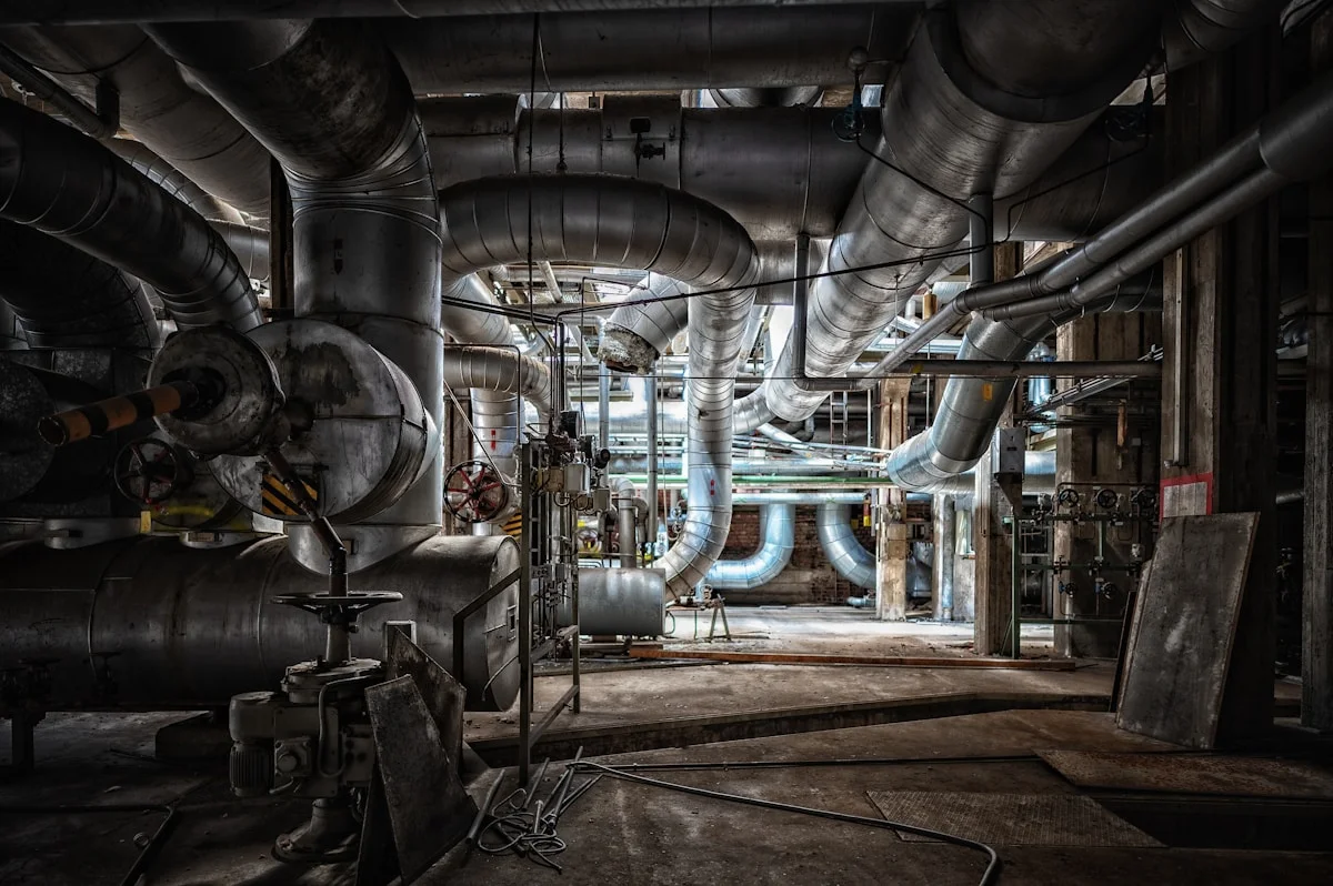
The repair-or-replace decision hinges on remaining structural integrity, projected lifecycle cost, and compliance exposure — not upfront material price alone. A panel system with less than 60% effective R-value retention typically warrants replacement, not patchwork.
Deciding whether to repair or replace degraded industrial insulation requires a disciplined evaluation framework. Facilities managers who prioritize the initial price per linear foot over total lifecycle cost frequently make decisions that compound expenses over a three-to-five-year horizon. The core variables are damage severity, remaining service life, compliance risk, and lifecycle cost — each carrying equal weight in a sound decision matrix.
Evaluating Damage Severity and Core Integrity
The first step is quantifying the extent of insulation degradation rather than relying on surface-level visual inspection. Foam core panels — including XPS, PET, PU, PVC, and PMI variants — degrade through moisture ingress, core compression, and facing delamination. The distinction between localized damage and systemic failure is critical: a single compromised panel section affects only a fraction of the thermal envelope, while widespread moisture migration through panel joints indicates a systemic failure that repair cannot resolve.
Core compression is one of the most overlooked indicators of irreparable degradation. When foam cores experience sustained compressive loads exceeding their design threshold — common in floor applications and heavy-equipment mounting zones — the cell structure collapses and thermal resistance drops disproportionately. A core that has lost more than 25% of its original density typically cannot be restored to specification through repair. Honeycomb core panels (PP, fiberglass, aramid, and carbon fiber variants) face a different failure mode: cell wall rupture or core-face bond separation. In these cases, the structural contribution of the core is compromised alongside the thermal contribution, making repair an unreliable intervention.
Facing delamination — the separation of the outer skin from the core — is another decisive factor. When gelcoat on GRP/FRP facing develops micro-cracking and moisture penetrates the interface, the bond strength degrades progressively. A delamination zone exceeding 15% of any single panel’s surface area signals that the facing material has reached the end of its functional life. Patch repairs in these conditions fail because the underlying adhesive bond is already compromised, and thermal bridging through the delaminated zone continues to degrade system performance.
Remaining Service Life and Performance Retention
Estimating remaining service life requires understanding how different core materials degrade under specific environmental conditions. XPS foam maintains stable thermal performance for 20 to 30 years in dry, controlled environments. However, in environments with repeated thermal cycling and moisture exposure — such as refrigerated truck bodies or cold storage facilities — XPS can experience significant R-value loss within 8 to 12 years due to gas diffusion through the closed-cell structure. PET foam offers superior moisture resistance and retains thermal performance longer in wet environments, while PU foam sits between these extremes in terms of longevity and environmental sensitivity.
The practical threshold for replacement versus repair is often defined by effective R-value retention. When diagnostic testing — including infrared thermography and core sampling — reveals that a panel system has dropped below 60% of its original thermal resistance, repair becomes an economically irrational choice. The energy cost differential between a degraded system and a new installation typically exceeds the repair cost within 18 to 24 months, making continued repair a false economy. This is where the lifecycle cost calculation most often goes wrong: the initial repair quote appears modest, but the recurring maintenance frequency and energy penalty are excluded from the comparison.
Compliance Risk and Regulatory Exposure
Compliance risk is a factor that frequently tips the balance toward replacement, particularly in regulated industries. Fire-rated insulation assemblies — such as PIR sandwich panels with specific fire performance classifications — must maintain their certified performance characteristics to remain compliant with building codes and insurance requirements. Once a fire-rated panel system is breached through damage or partial repair, the original certification no longer applies to the modified assembly. Insurance carriers and regulatory inspectors do not accept “repair patches” as equivalent to the original certified system.
Corrosion under insulation (CUI) represents another compliance and safety concern that repair cannot adequately address. When insulation systems fail to maintain a continuous thermal barrier, condensation forms on underlying metal substrates, accelerating corrosion. In process plants, storage facilities, and transportation applications, CUI-related failures can lead to regulatory violations, production shutdowns, and safety incidents. A repair approach that addresses the insulation damage without correcting the underlying moisture management failure will allow CUI to progress unchecked — often at an accelerating rate.
Lifecycle Cost Analysis: The True Decision Metric
The most reliable method for evaluating repair versus replace is a full lifecycle cost analysis that accounts for three components: initial investment, operational cost, and maintenance cost. The operational cost component is where most evaluations fail. A repaired insulation system with degraded thermal performance increases energy consumption continuously. For a refrigerated facility, this energy penalty can range from 15% to 40% above design specifications, depending on the severity of degradation and the temperature differential across the insulation envelope. Over a five-year period, these energy costs often exceed the price difference between repair and full replacement.
Maintenance cost is the second hidden component. Facilities with degraded insulation systems experience higher inspection frequency, more frequent emergency repairs, and greater operational disruption. Each repair event requires scheduling, labor, material procurement, and potential production downtime. When maintenance frequency exceeds two repair cycles per year for the same insulation system, the total cost of ownership typically surpasses the cost of replacement within three to four years. This is the threshold where the “high maintenance frequency” concern becomes a quantifiable financial liability rather than an operational inconvenience.
📋 Decision Matrix: Repair vs. Replace
- Repair is viable when: Damage is localized to less than 10% of total panel area, core density retention is above 75%, facing adhesion is intact, and the system remains within certified fire-rating boundaries. Energy penalty is below 10% of design specifications.
- Replace is required when: Core compression exceeds 25% density loss, delamination covers more than 15% of panel surface, effective R-value retention drops below 60%, fire-rating certification is compromised, or CUI is present on underlying substrates. Maintenance frequency exceeds two repair events per year.
- Economic evaluation threshold: When the combined annual cost of energy penalty, maintenance labor, and operational downtime exceeds 40% of the replacement cost amortized over a five-year period, replacement is the economically optimal choice regardless of repair feasibility.
The most costly repair-or-replace mistake is treating systemic degradation as a localized problem. When moisture has migrated through panel joints or fastener penetrations, the damage extends beyond the visible failure point. Repairing only the visible area leaves compromised insulation in place, and the energy penalty continues to accumulate. Always conduct core sampling and infrared scanning across the full panel field before committing to a repair strategy.
Material-Specific Considerations for Composite Panel Systems
Different composite panel configurations respond differently to degradation and repair interventions. CFRT sandwich panels with XPS, PET, PU, or PVC cores offer varying repair tolerances based on their facing material properties. GRP-faced panels with gelcoat coatings can be patched effectively when the underlying core remains intact and dry. However, when gelcoat degradation has allowed moisture to reach the fiberglass-resin interface, the facing itself has reached end-of-life and patch repairs will delaminate within months.
Aluminum-faced sandwich panels present different repair considerations. Aluminum facings are susceptible to galvanic corrosion when moisture breaches the core-facing interface, particularly in environments with salt exposure or high humidity. Once galvanic corrosion begins on the aluminum facing, the structural integrity of the panel degrades progressively, and repair is not a viable long-term solution. Honeycomb core panels — whether PP, fiberglass, or carbon fiber construction — require specialized repair techniques that restore both the core structural contribution and the thermal barrier. Standard foam-core repair methods do not apply to honeycomb constructions.
For applications in demanding environments — refrigerated transport, marine vessels, RV structures, and mobile facilities — the selection of core material at the design stage significantly affects the repair-versus-replace calculus. PMI foam cores offer superior thermal stability and moisture resistance but carry a higher initial cost that is justified when lifecycle cost analysis favors long-term performance over short-term savings. PET foam provides an intermediate balance of performance and cost. The optimal choice depends on the specific thermal requirements, environmental exposure, and lifecycle cost parameters of each application.
Integrating the Decision into a Long-Term Asset Strategy
The repair-or-replace decision should not be made in isolation. It is most effective when integrated into a facility-wide insulation asset management strategy that includes routine inspection scheduling, performance monitoring, and proactive replacement planning. Facilities that implement infrared thermography surveys on a biannual basis can identify degradation patterns before they reach the repair-or-replace decision point, allowing for planned replacement that is cost-effective and operationally efficient.
Predictive performance monitoring — tracking thermal resistance trends over time through periodic testing — provides the data necessary to forecast replacement cycles with accuracy. When monitoring data shows a consistent decline in R-value retention that exceeds the expected degradation rate for the installed material system, it indicates either an environmental exposure that exceeds the original design parameters or a manufacturing quality issue. In either case, the data supports a replacement decision that is defensible from both a technical and financial perspective.
The financial justification for replacement over repair is strongest when the analysis includes the full cost of operational disruption. Each repair event requires production scheduling adjustments, labor deployment, and potential partial facility shutdown. In high-utilization environments such as continuous manufacturing operations or fleet deployment cycles, these disruption costs can be substantial. A replacement program that is planned and executed during scheduled maintenance windows eliminates the recurring disruption costs associated with emergency and reactive repair interventions.
Build a Long-Term Insulation Plan
A proactive insulation plan transforms maintenance from reactive spending into predictable operational cost. The right combination of inspection discipline, material selection, and monitoring technology extends panel service life by decades.
Establish Routine Inspection Schedules for Sandwich Panel Systems
Most facility managers treat sandwich panel inspection as an annual checkbox exercise. This approach misses the compounding damage that occurs between visual checks. Moisture migration, fastener loosening, and facing micro-cracks develop on different timelines depending on climate exposure, thermal cycling frequency, and mechanical load patterns.
A structured inspection framework divides surveillance into three tiers: daily visual sweeps by operations staff, quarterly technical assessments using infrared thermography and moisture mapping, and annual comprehensive audits by qualified engineers. Each tier targets different failure modes and requires different instrumentation.
Our engineering team has found that facilities implementing tiered inspection protocols reduce unplanned downtime by 60 to 70 percent compared to reactive maintenance models. The initial investment in infrared equipment and technician training pays for itself within the first maintenance cycle through early defect detection.
- Monthly visual checks: Document any discoloration, surface cracking, or sealant degradation on exposed panel faces, particularly around roof penetrations, joint seams, and fastener points.
- Quarterly thermal imaging: Scan all panel surfaces under consistent temperature differential conditions to identify hidden moisture accumulation, core voids, and thermal bridge formation.
- Annual structural audit: Conduct core sampling at representative locations, test fastener torque retention, measure facing adhesion strength, and correlate thermal performance data against baseline specifications.
Select Appropriate Core Materials for Specific Environmental Conditions
Core material selection represents the single most consequential decision in insulation lifecycle planning. The wrong core for your operating environment creates compounding performance degradation that no amount of maintenance can fully reverse. Foam cores and honeycomb structures behave fundamentally differently under thermal stress, moisture exposure, and mechanical loading.
Closed-cell foam cores deliver consistent thermal resistance across stable environments but require careful evaluation for applications involving sustained high humidity or direct water exposure. PMI foam offers superior performance at elevated temperatures but carries a premium cost that may not justify its use in standard refrigerated transport applications. PET foam provides an environmentally stable alternative with excellent moisture resistance and dimensional stability across wide temperature ranges.
Honeycomb cores present a different engineering calculus. While they deliver exceptional strength-to-weight ratios, the cellular structure creates potential convection pathways in dynamic thermal environments. Our testing demonstrates that PP honeycomb cores perform reliably in static building applications but require careful evaluation for refrigerated vehicle bodies subject to constant temperature cycling and vibration. In these mobile applications, closed-cell foam cores often deliver more consistent thermal performance over extended service life.
When evaluating core materials for your specific application, we recommend requesting comparative test data under conditions that mirror your actual operating environment. Generic lab specifications measured at standard temperature and humidity often mask performance differences that become critical under real-world conditions.
- Marine and high-humidity environments: Prioritize PMI or PET foam cores with waterproof gelcoat facings to minimize moisture absorption and maintain thermal resistance over extended service periods.
- Refrigerated transport applications: Closed-cell PU or PVC foam cores typically deliver more consistent thermal performance than honeycomb structures under repeated thermal cycling and vibration exposure.
- Static building construction: Honeycomb cores provide excellent structural performance with adequate thermal resistance when properly sealed against moisture ingress at all joints and penetrations.
- Extreme temperature environments: PMI foam cores maintain structural integrity and thermal performance at temperatures where standard PU or PVC foams begin to degrade.
Implement Protective Facing and Coating Maintenance Protocols
The facing material and its surface coating represent the first line of defense against environmental degradation. Once the facing is compromised, moisture reaches the core material and initiates a cascade of performance losses that become increasingly expensive to remediate. Gelcoat maintenance on GRP panels and surface protection on CFRT sheets require fundamentally different approaches based on material chemistry and exposure conditions.
Gelcoat surfaces on fiberglass panels provide excellent waterproof protection when intact, but UV degradation creates micro-cracking that allows moisture penetration over time. Regular washing with appropriate cleaners and periodic application of UV-protective coatings extends gelcoat service life significantly. Our facility testing shows that panels receiving annual gelcoat maintenance in harsh UV environments maintain surface integrity for 15 to 20 years, compared to eight to 12 years for untreated panels under identical conditions.
CFRT facing materials offer different maintenance requirements. The thermoplastic matrix provides inherent chemical resistance and flexibility that reduces cracking propensity compared to traditional thermoset systems. However, surface scratching and abrasion during routine operations can compromise protective qualities and create initiation points for more serious damage.
The economics of facing maintenance often get overlooked in initial project budgets. A comprehensive coating maintenance program typically costs less than 5 percent of the original panel investment annually, yet it prevents replacement costs that can exceed 40 percent of original panel value when core damage has progressed beyond surface-level repair.
- Annual gelcoat inspection and maintenance: Clean surfaces with non-abrasive cleaners, inspect for micro-cracking under raking light, and apply UV-protective coating to panels exposed to direct sunlight for more than six months per year.
- CFRT surface protection: Implement floor and contact area protection in high-traffic zones, repair surface scratches promptly with compatible thermoplastic repair compounds, and avoid abrasive cleaning methods that remove protective surface layers.
- Sealant and joint maintenance: Inspect all panel joints, fastener seals, and penetration flashings quarterly, replacing deteriorated sealant before moisture reaches core materials.
- Impact damage response: Address any facing punctures or cracks within 48 hours of discovery to prevent moisture migration into core materials, regardless of apparent severity.
Integrate Predictive Performance Monitoring into Facility Operations
The most sophisticated inspection and maintenance programs still operate reactively if they lack continuous performance data. Predictive monitoring transforms insulation management from scheduled maintenance based on time intervals to condition-based decisions driven by actual performance degradation rates. This shift eliminates both unnecessary maintenance spending and catastrophic failure events caused by undetected deterioration.
Modern monitoring systems integrate multiple data streams: surface and core temperature sensors, moisture content measurements, thermal resistance calculations, and structural load monitoring. These systems establish baseline performance characteristics during initial commissioning and track deviations that indicate emerging problems before they reach critical thresholds.
For refrigerated transport applications, we recommend installing continuous monitoring systems that track internal temperature stability, compressor cycling patterns, and thermal performance metrics throughout each journey. Data patterns reveal insulation degradation long before temperature control failures become apparent to operators. Facilities managing fixed refrigerated spaces can implement similar monitoring with strategically placed sensors at representative locations throughout the insulated envelope.
The business case for predictive monitoring extends beyond failure prevention. Performance data provides documentation for warranty claims, insurance negotiations, and regulatory compliance audits. It also generates the historical data needed to refine maintenance schedules and replacement planning for future projects, creating a continuous improvement loop that reduces lifecycle costs across your entire asset portfolio.
- Baseline performance documentation: Establish comprehensive thermal and structural performance baselines during initial commissioning, documenting conditions, measurements, and environmental parameters for future comparison.
- Continuous monitoring deployment: Install sensor networks at strategically representative locations, prioritizing areas most susceptible to moisture ingress, thermal bridging, and mechanical stress based on your specific application requirements.
- Alert threshold configuration: Define performance deviation thresholds that trigger maintenance alerts, balancing sensitivity to catch problems early against alert fatigue from excessive false positives.
- Data-driven maintenance scheduling: Transition from calendar-based maintenance to condition-based scheduling using monitored performance data, reducing unnecessary interventions while ensuring problems are addressed before they escalate.
When evaluating insulation suppliers, ask about their experimental testing protocols and whether they perform application-specific validation before recommending core materials. Our engineers test composite panels under conditions that simulate your actual operating environment, not just standard laboratory specifications. This approach prevents costly mismatches between material performance and real-world requirements.
Do not assume that all foam cores perform identically under moisture exposure. PVC, PU, XPS, and PET foams exhibit vastly different moisture absorption rates and long-term thermal resistance retention when subjected to sustained humidity. Always request comparative moisture absorption data and long-term thermal performance projections for your specific environmental conditions before finalizing material selection.
| Planning Phase | Critical Factor | Rax Custom Solution | Long-Term Benefit |
|---|---|---|---|
| Economic Assessment | Total Cost of Ownership | Cost-effective composite engineering with lightweight cores | Maximizes ROI through energy savings and durability |
| Structural Design | Strength-to-Weight Ratio | CFRT/GRP Sandwich Panels with Honeycomb or XPS cores | Reduces vehicle weight while maintaining high load-bearing capacity |
| Thermal Performance | Thermal Insulation Performance | Closed-cell PU, PET, or PVC Foam cores with GRP facings | Superior thermal insulation minimizing energy loss in transit |
| Safety Compliance | Fire Resistance Standards | PIR Sandwich Panels and Fire-Retardant FRP facings | Ensures compliance with strict global fire safety regulations |
| Lifecycle Durability | Environmental Resistance | Waterproof Gel-coated FRP sheets with marine-grade cores | Extends service life with low maintenance requirements |
Conclusion
Stop treating insulation as an install-and-ignore purchase. Effective protection hinges on rigorous material selection and aggressive maintenance schedules. You must catch moisture ingress early or face catastrophic core failure later. Thermal bridges at joints are silent budget killers that destroy efficiency over time. We have seen facilities save thousands simply by upgrading fire ratings and addressing delamination immediately. Prioritize lifecycle costs over upfront unit price to avoid premature replacement. Do not wait for visible cracks to appear on the facing.
- Audit your current panel joints for compression and density loss.
- Verify your thermal conductivity data against actual service conditions.
- Consult our engineering team to review your specific environmental constraints.
Frequently Asked Questions
Can I retrofit insulation on older industrial panels?
Yes, retrofitting is often a cost-effective alternative to full panel replacement. Surface coatings and protective facing upgrades can restore thermal performance and extend service life. However, if the core has suffered significant compression or moisture saturation, retrofitting alone may not suffice. A structural assessment should precede any retrofit to determine whether patch repair or full replacement is more economical over the panel’s remaining lifecycle.
How do I balance thermal performance with structural load requirements?
Thermal and structural performance are not mutually exclusive but require careful material pairing. Thicker foam cores improve insulation but may reduce load capacity unless reinforced with appropriate facings like GRP or aluminum. Honeycomb cores offer an excellent strength-to-weight ratio for applications needing both insulation and structural integrity. Engineering simulations and experimental testing help identify the optimal core-skin combination for your load and thermal specifications.
How do dynamic environments like trucks affect insulation longevity?
Vibration, thermal cycling, and mechanical stress in moving vehicles accelerate insulation degradation compared to static installations. Honeycomb and CFRT cores generally outperform standard foam cores under dynamic conditions due to their resilience and resistance to compression set. Selecting materials rated for vehicular use and securing proper mounting systems reduces premature failure and maintenance frequency.
What is the typical lifespan of composite sandwich panel insulation?
Well-maintained composite sandwich panels with quality core and facing materials typically last 20 to 30 years in static industrial applications. Lifespan decreases significantly in dynamic environments such as vehicles or marine vessels where thermal cycling and vibration accelerate material fatigue. Proper coating maintenance and routine inspections can extend service life beyond the baseline estimate.
What fire rating standards apply to industrial sandwich panels?
Key standards include EN 13501 for European markets and ASTM E84 for North America, both classifying panels by flame spread and smoke development. PIR and rockwool cores typically achieve higher fire ratings compared to standard PU or XPS cores. Always verify that selected panels meet the fire classification required by your local building code and industry regulations before procurement.