
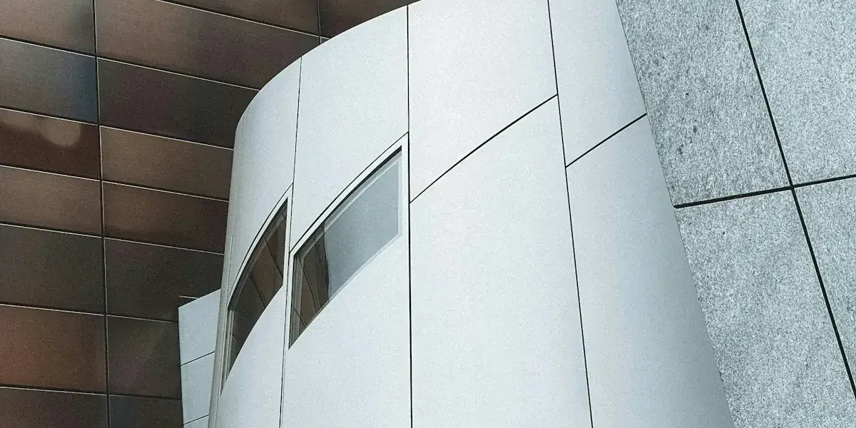
During severe coastal storms and intense thunderstorm squalls, horizontal entrance canopies face an aerodynamic environment far more violent than vertical building walls. In our structural metal engineering division, we regularly inspect commercial facilities where overhead canopies tore loose from secondary framing or accumulated ponding water that dissolved exterior caulking joints. Selecting the right cladding material for overhead spans requires balancing high structural flexural rigidity against dead-weight loads imposed on cantilevered steel outriggers. When engineered correctly with dedicated structural extrusion systems, exterior aluminum composite panels provide an exceptionally durable, weather-tight overhead envelope that withstands severe weather for decades.
In our architectural manufacturing facility, our team fabricates hundreds of overhead canopy and soffit cassettes every month. We enforce an internal engineering rule requiring concealed longitudinal stiffener extrusions bonded to the rear of every wide-span panel to prevent aerodynamic oil-canning and manage negative uplift pressures. While commercial developers often assume horizontal roof panels behave like vertical cladding, overhead installations must actively manage gravity ponding, thermal movement, and internal water evacuation. Mastering these core detailing protocols ensures your entrance canopy remains structurally sound and maintenance-free throughout its service life.
Why Flat Aluminum Panel Roofs Always Fail
A fundamental engineering reality of horizontal composite panel assemblies is that a perfectly flat, zero-degree roof deck is structurally prohibited. Even when structural steel beams appear level during framing inspection, unavoidable material tolerances and deflection under dead loads produce localized depressions between purlins. Rainwater collects in these low spots, forming stagnant pools that never evaporate completely between storm cycles. Over multiple months, continuous water ponding creates an aggressive chemical poultice that initiates chemical hydrolysis within exterior finishes. When you inspect finished projects, you will discover that evaluating coating durability is closely tied to how well you verify PVDF coating quality before authorizing shipment.
Beyond finish degradation, standing water creates a progressive structural deflection hazard known across the roofing industry as ponding instability. Water weighs approximately one kilogram per liter, or 1,000 kilograms per cubic meter. As water accumulates in a shallow depression, its concentrated dead weight deflects the composite panel downward by an additional millimeter. This localized sag immediately draws adjacent runoff into the deepening depression, increasing the water volume and driving further structural deflection. Over multiple seasons, this self-reinforcing weight cycle exerts continuous tensile creep on secondary structural fasteners, eventually pulling screws completely through the aluminum support flanges.
To permanently prevent ponding water, architectural canopy specifications must mandate a continuous, mathematically verified drainage slope of at least 1:20 (5%). This 5% minimum gradient ensures that rainfall and melting snow evacuate rapidly into perimeter collection gutters. Rapid drainage also flushes away airborne pollutants, industrial chemical deposits, and coastal salt crystals before they dry onto the metal. If alkaline dust sits in stagnant puddles under solar heat, it concentrates into an abrasive paste that etches the protective clear coat, permanently scarring the panel aesthetic.
Fabricating this continuous slope into the primary structural steel outriggers is far superior to shimming secondary aluminum framing on site. Field shimming introduces mechanical play that loosens under repeated wind reversals. When structural steel beams are manufactured with an engineered downward pitch, secondary aluminum sub-framing attaches flush against the main frame. This integrated alignment guarantees a uniform plane that sheds water predictably into drainage channels without creating localized pooling pockets.
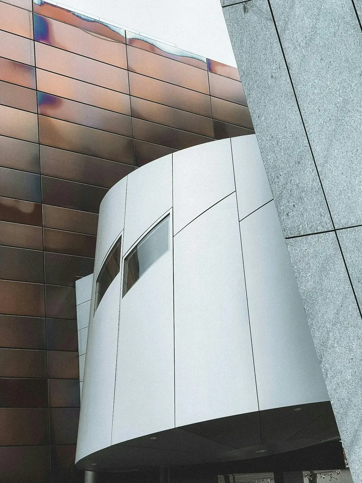
Calculate Wind Uplift Limits Under ASCE Standards
Cantilevered commercial entry canopies experience aerodynamic pressure profiles completely different from standard enclosed vertical walls. As high-velocity wind strikes an upright facade, the air mass diverts downward and outward across the canopy deck. Simultaneously, wind flowing beneath the canopy accelerates through the ground-level entryway, creating an intense suction vortex underneath the ceiling soffit. This aerodynamic phenomenon produces high net negative wind uplift forces that pull outward on fasteners. Facade engineers must calculate these localized pressures using ASCE 7 wind load provisions to verify connection safety.
Aerodynamic wind calculations reveal that pressure distributions are never uniform across a horizontal canopy deck. While central interior zones experience moderate uplift pressures, perimeter edges and outboard corners experience severe localized aerodynamic vortex shedding. Under ASCE 7 Chapter 30 design guidelines, corner regions designated as Zone 3 generate net negative pressure coefficients exceeding -2.4 to -3.2 Cp. In practical engineering terms, a 130-mile-per-hour design wind speed creates localized upward suction exceeding 45 pounds per square foot (2.15 kN/m²) at canopy corners. Structural framing must double perimeter fastener density and reduce outrigger spacing along these leading edges to prevent wind suction from tearing corner cassettes away from purlins.
Under peak storm loads, panels must satisfy rigorous structural deflection limits verified through ASTM E330 structural testing. The accepted industry threshold mandates that maximum center-point deflection must not exceed L/180 of the unsupported panel span. For a panel spanning 1500 mm between support extrusions, total deflection under negative suction cannot exceed 8.3 mm. Exceeding this boundary stresses the routed perimeter return folds, causing metal fatigue and cracking over seasonal storm cycles.
To satisfy L/180 deflection limits on large panels without adding visible face fasteners, fabricators bond concealed aluminum stiffeners to the unexposed backside of the panel. These stiffeners attach using high-strength structural silicone or structural acrylic tape, transferring wind uplift loads into secondary purlins. This reinforcement maintains a flat surface appearance during wind gusts, eliminating distracting visual distortions known across the metal industry as oil-canning.
Designing Concealed Gutters for Clean Roof Lines
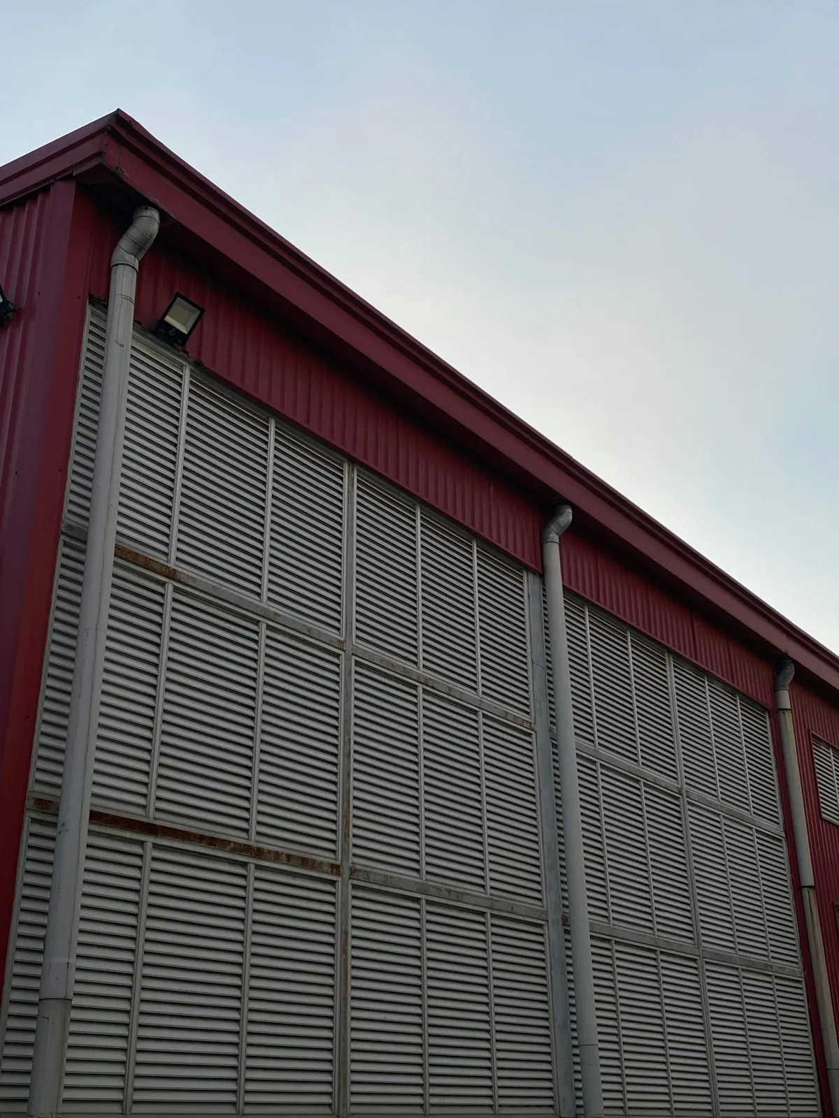
Architectural canopies require robust rainwater drainage while preserving clean, uncluttered sightlines from ground level. External exposed downspouts look industrial and interrupt modern facade aesthetics. Premium commercial canopies utilize concealed perimeter gutters tucked behind the vertical fascia panels. Rainwater flowing down the five percent roof slope discharges directly into an internal stainless steel or heavy-gauge aluminum gutter trough concealed beneath the outer cassette edge.
These internal gutters must feature fully welded corners and an unbroken EPDM waterproofing membrane liner. If thermal expansion creates a hairline crack in a welded gutter seam, water drips unseen onto the ceiling soffit panels below. In cold climates where nighttime temperatures drop below freezing, internal gutter troughs require factory-installed self-regulating electric heat tracing cables. Without heated gutters, melting snow refreezes into solid ice dams that block drainage outlets and push water over the rear panel flashing.
Internal drainage lines should connect directly into the building interior rainwater conductor network or route down through structural steel support columns. Routing downspouts through hollow structural columns protects drainage pipes from vandalism, accidental impact damage, and exterior thermal cycling. Inspection cleanouts installed at the base of each column enable maintenance teams to flush accumulated organic debris quickly during routine building service.
Accommodating Thermal Expansion Along Canopy Spans
Aluminum possesses a high coefficient of thermal expansion, expanding approximately 2.4 mm per meter across a 100-degree Celsius temperature range. On an expansive sixty-meter commercial airport canopy exposed to blazing direct sunlight followed by cold nighttime radiational cooling, total dimensional movement reaches significant distances. Dark-colored exterior finishes, such as charcoal grey, dark bronze, or black coil coatings, absorb solar radiation aggressively, driving surface metal temperatures up to 80 degrees Celsius on midsummer afternoons. When evening ambient temperatures drop to 20 degrees Celsius, the metal experiences a rapid 60-degree thermal swing that produces severe expansion and contraction stresses across the entire framing grid.
If installation contractors drive rigid self-tapping screws through fixed round holes, the expanding metal binds tightly against fastener shanks, resulting in loud popping noises and severe panel buckling. To absorb continuous thermal movement without structural distress, secondary canopy framing extrusions must utilize engineered slotted holes. Fasteners anchor through the exact center of these slotted holes, supported by low-friction nylon or neoprene isolation washers. The fasteners are torqued using calibrated clutch drivers to ensure snug contact while allowing the aluminum skin to slide freely along the slot axis as ambient temperatures fluctuate throughout the year.
Perimeter caulking joints must also be engineered to accommodate this ongoing dimensional movement. Standard architectural joints require a minimum width of 15 mm to 20 mm, sealed with high-performance low-modulus silicone possessing at least fifty percent joint movement capability. Specifying rigid, low-movement polyurethanes leads to early cohesive tear failures, allowing driving rain to bypass the outer cladding barrier.
Align Exterior Fascia Panels with Underside Soffits
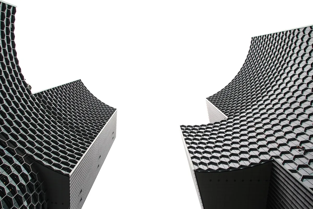
The visual success of an architectural canopy depends heavily on the alignment between vertical fascia panels and horizontal soffits. When pedestrians approach a commercial entrance, their eye tracks upward from the underside ceiling directly to the outer perimeter edge. If vertical fascia joints fail to align with horizontal soffit reveals, the canopy looks disorganized. Achieving crisp joint alignment requires precise structural steel shop drawings and coordinated secondary extrusion grids.
During pre-construction coordination, our engineering team advises project architects to compare overhead canopy framing configurations using quantitative metrics. The table below outlines key engineering differences between cantilevered canopies and suspended entrance canopies to assist your structural planning.
| Structural Engineering Parameter | Cantilevered Outrigger Canopy | Suspended Tie-Rod Canopy |
|---|---|---|
| Primary Load Transfer Path | Moment arm connections into columns | Tensile tie-rods to upper wall anchors |
| Typical Projection Limit | 1.5 to 3.0 meters maximum | 2.5 to 5.0 meters with support cables |
| Wind Uplift Sensitivity | High; severe moment stress at wall | Extreme; rods can buckle under uplift |
| Minimum Panel Thickness | 4 mm with 0.5 mm aluminum skins | 4 mm or 6 mm with rear stiffeners |
| Joint Reveal Alignment | Flush matching grid lines | Interrupted by tie-rod brackets |
For projects requiring precise fabrication, always review incoming materials carefully. When project managers evaluate aluminum composite panel quality on site, measuring core density and skin thickness ensures panels endure horizontal structural spans without creeping or sagging over time.
4 Costly Mistakes in Canopy Roof Construction
Specifying Combustible Cores for Overhead Walkways
A severe life-safety mistake in canopy engineering is specifying low-cost polyethylene (PE) core panels for overhead structures. In a ground-level fire, flames rise directly into the canopy underside. Combustible polyethylene cores melt rapidly, generating flaming plastic droplets that fall onto escaping occupants below. International building codes strictly mandate Fire Retardant (FR) mineral cores meeting Class A or EN 13501-1 B-s1,d0 standards for all overhead commercial canopies.
Omitting Vapor Permeable Air Barriers in Soffits
Many contractors assume horizontal soffit ceilings require no weather barrier because they are protected from direct rainfall. However, warm humid air naturally rises into the unconditioned soffit cavity. When temperatures drop at night, this trapped moisture condenses against cold structural steel purlins, causing water to drip onto electrical lighting fixtures. Installing a continuous, vapor-permeable weather barrier behind soffit cassettes allows vapor to escape while blocking liquid condensation droplets.
Allowing Direct Foot Traffic During Roof Maintenance
Maintenance technicians frequently climb onto overhead canopies to service exterior lights, window washing gear, or rooftop signage. Walking directly on composite panel surfaces crushes the core material and causes localized yielding in thin aluminum skins. These dented footprints trap water, accelerating coating degradation. Canopy designs must incorporate dedicated structural aluminum walkways mounted above the panel deck, transferring foot-traffic loads directly into primary steel purlins.
Fastening Solar Brackets Directly into Panel Skins
With increasing emphasis on renewable building energy, facility managers often attempt to mount solar photovoltaic panels to canopy decks. Driving mounting screws directly into thin composite aluminum skins is an engineering failure. Strong wind uplift forces easily strip mechanical fasteners out of thin metal faces. Solar racking systems must penetrate through the composite cladding and bolt directly into heavy structural steel purlins underneath.
Engineered Overhead Canopy Panel Solutions
Designing overhead architectural canopies exposed to severe wind loads and demanding aesthetic requirements? Our engineering division manufactures high-rigidity aluminum composite panels engineered for horizontal spans. We supply complete deflection calculations, custom perimeter extrusion framing, and certified Class A fire-rated mineral cores for commercial architectural projects.
Frequently Asked Questions About Canopy Panels
What minimum slope is required for an aluminum composite panel roof?
Horizontal canopy panels require a minimum slope of 1:20 (5%). This positive gradient prevents standing water ponding, eliminates chemical hydrolysis on PVDF finishes, and washes away accumulated atmospheric dust.
How do engineers resist wind uplift on entrance canopies?
Engineers design concealed aluminum stiffeners bonded to panel backsides with structural silicone. Panels are tested under ASTM E330 to ensure deflection does not exceed L/180 of the unsupported span.
Can workers walk directly on composite panel canopy roofs?
No, walking directly on panels causes localized skin denting and core crushing. Dedicated aluminum grating walkways mounted directly to structural steel purlins are mandatory for roof maintenance access.
Why do some metal canopies produce loud popping noises?
Popping noises indicate restricted thermal expansion. When framing screws lack slotted holes or nylon slip washers, expanding aluminum binds tightly before releasing violently, producing loud structural popping sounds.
What core material is mandated for overhead commercial canopies?
Building codes mandate Fire Retardant mineral cores for overhead installations. Combustible polyethylene cores are prohibited because melting plastic produces flaming droplets during a ground-level architectural fire.